Icom IC-SAT100M User manual

OPERATING MANUAL
7 TROUBLESHOOTING
6 SPECIFICATIONS AND OPTIONS
5 CONNECTING AND MAINTENANCE
4 MENU SCREEN
3 OTHER FUNCTIONS
2 BASIC OPERATION
1 PANEL DESCRIPTIONS
INTRODUCTION
SATELLITE PTT

i
INTRODUCTION
Thank you for choosing this Icom product.
This product is designed and built with Icom’s state of the art technology and craftsmanship.
With proper care, this product should provide you with years of trouble-free operation.
Important
READ ALL INSTRUCTIONS carefully before using the transceiver.
This OPERATING MANUAL contains advanced features and operating instructions for the IC-SAT100M.
READ also the BASIC MANUAL that is supplied with the transceiver.
KEEP THE MANUALS, because it contains important operating information that may be useful in the future.
Supplied accessories
Speaker
microphone Antenna unit
Angle bracket
Self-tapping screws for
attaching to a wall
(M6×30 mm)
Wing nut, Nuts,
Flat washers, and
Spring washers for
attaching to a mast
Mast clamp
Mounting screws (M5×12 mm),
Self-tapping screws (M5×20 mm),
Nuts, Flat washers, and
Spring washers
for mounting the transceiver
LAN cable
(20 m, 65.6 ft)
Microphone hanger
and
screw set
Mounting bracket
Cushion and sheet
for the mounting
bracket
Bolts (M4×8 mm),
Flat washers,
Spring washers
for mounting the antenna
DC power cable
(3 m, 9.8 ft)
Terminals for DC
power cable
(R2-6)
Spare
fuses (5A)
U-bolt

ii
Icom, Icom Inc. and the Icom logo are registered trademarks of Icom Incorporated (Japan) in Japan, the United States, the
United Kingdom, Germany, France, Spain, Russia, Australia, New Zealand and/or other countries.
The Bluetooth® word mark and logos are registered trademarks owned by Bluetooth SIG, Inc. and any use of such marks by
Icom Inc. is under license.
Other trademarks and trade names are those of their respective owners.
3M, PELTOR, and WS are trademarks of 3M Company.
AquaQuake™ is a trademark of Icom Incorporated.
All other products or brands are registered trademarks or trademarks of their respective holders.
Table of contents
INTRODUCTION ..................................................... i
Important ....................................................... i
Supplied accessories .................................... i
Table of contents ........................................... ii
Microphone Description................................. 1
1 PANEL DESCRIPTIONS ................................... 1
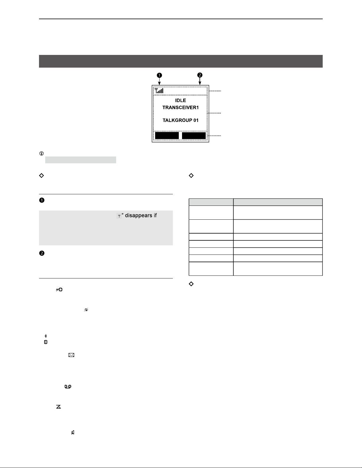
Function display ............................................ 2
2 BASIC OPERATION ......................................... 3
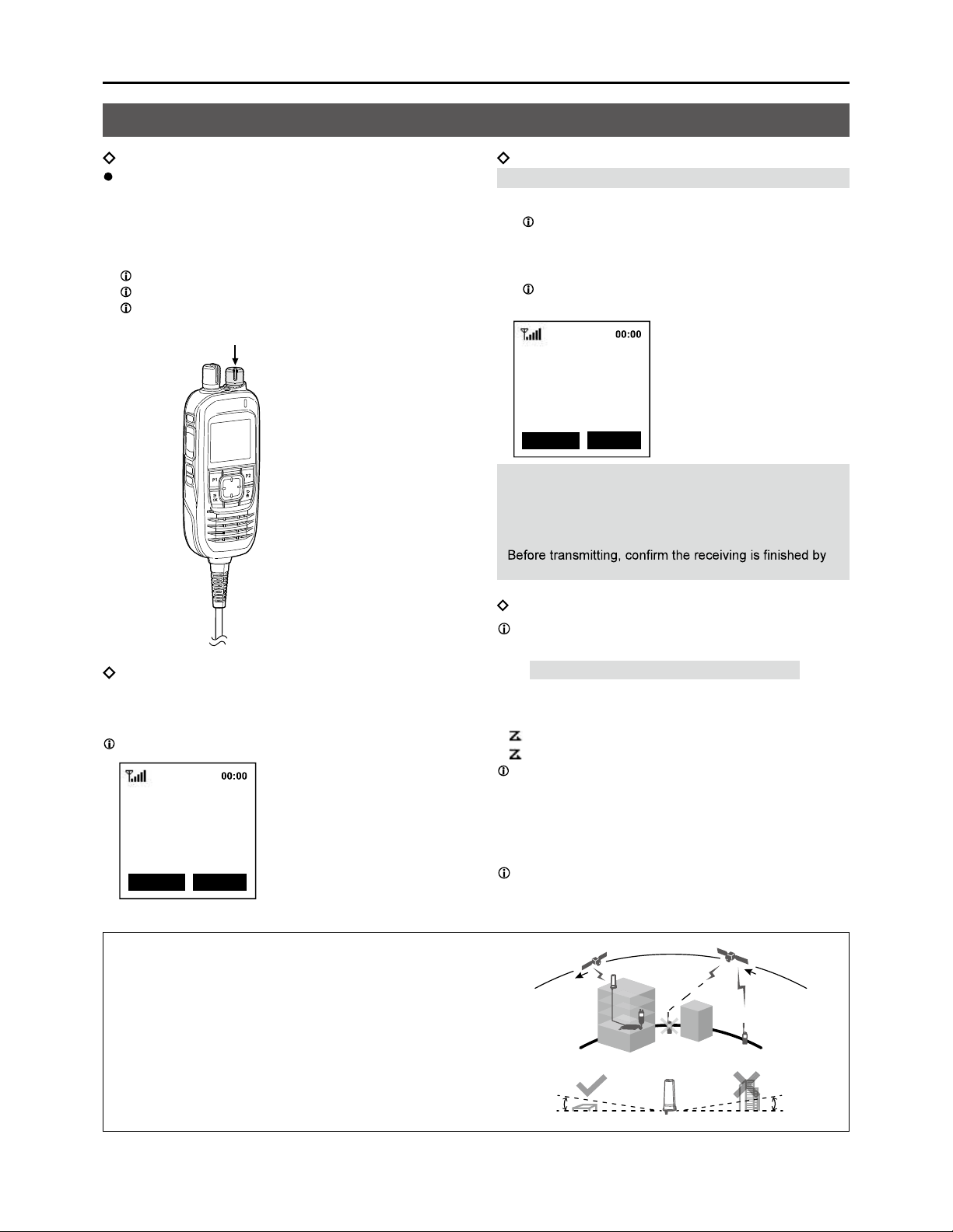
Receiving and transmitting ............................ 3
Using the Message function .......................... 4
3 OTHER FUNCTIONS ........................................ 4
Using the Emergency mode .......................... 4
Using the Key Lock function .......................... 4
Using the Surveillance function ..................... 5
Using the AquaQuake function ...................... 5
Using the Last Call Play function................... 5
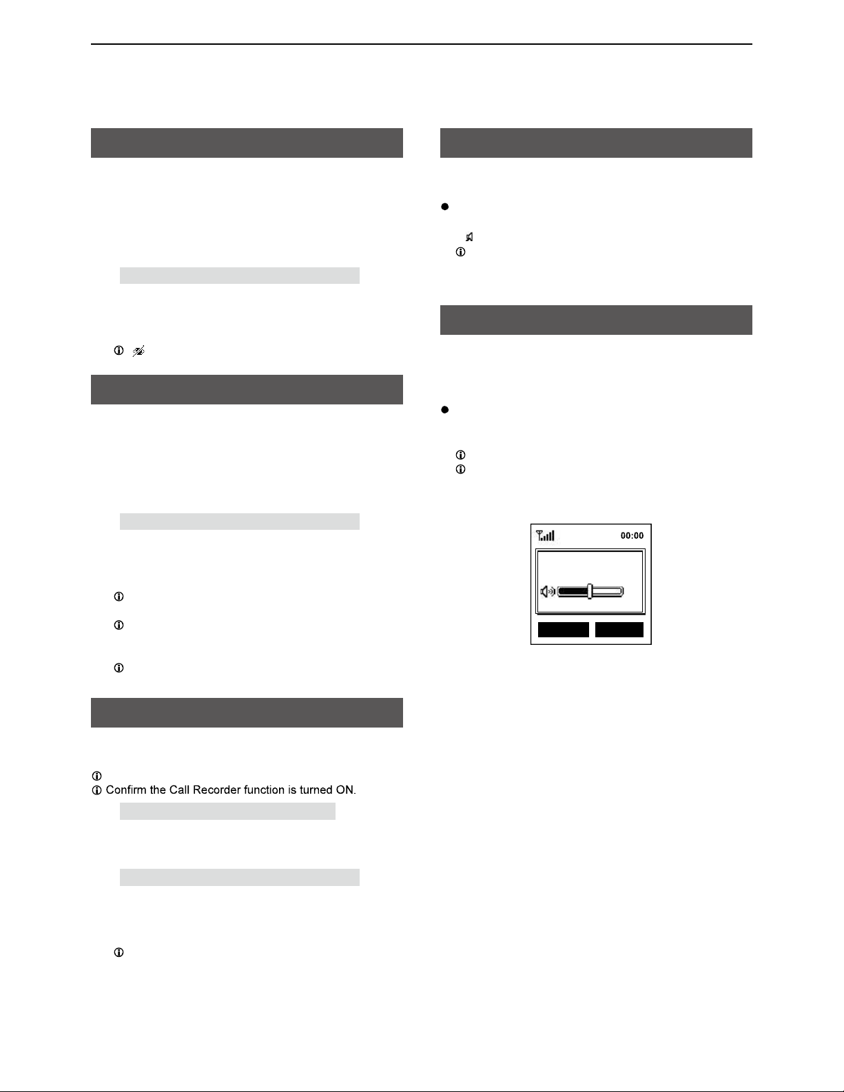
Using the RX Speaker function ..................... 5
Using the Public Address function ................. 5
4 MENU SCREEN ................................................ 6
Using the Menu screen ................................. 6
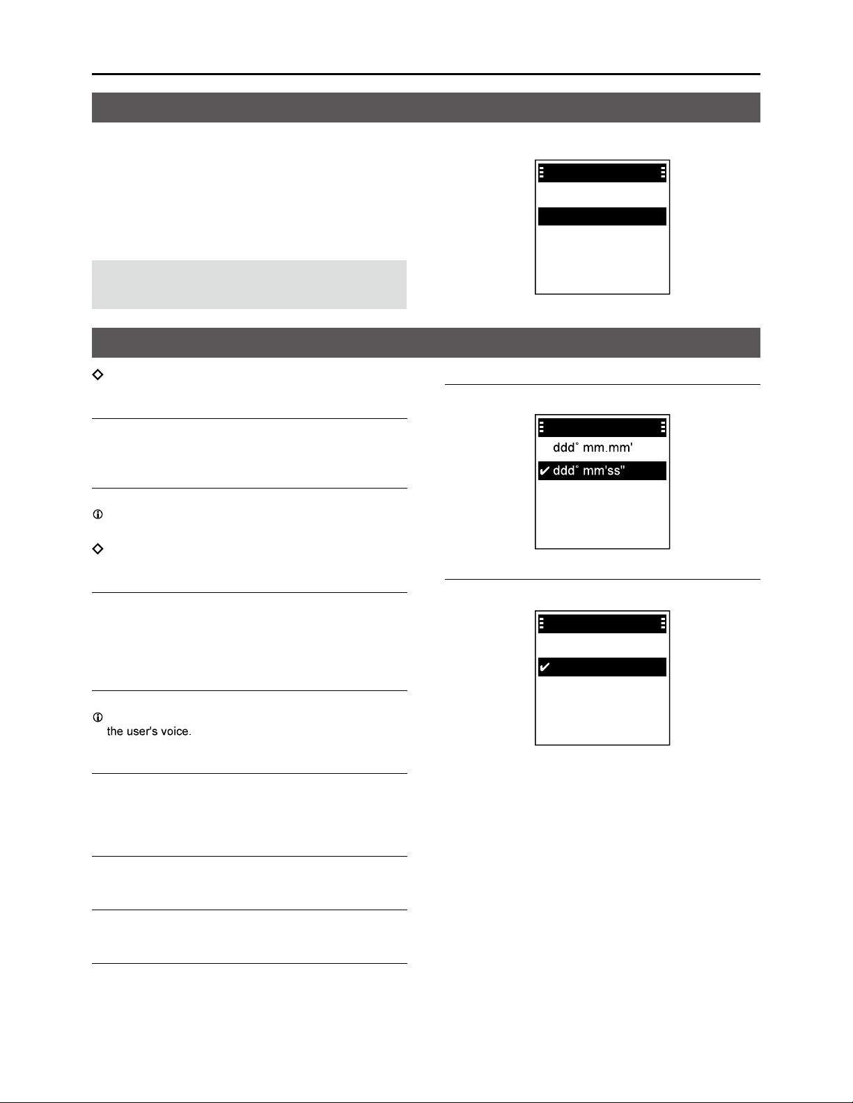
Menu items .................................................... 6
5 CONNECTING AND MAINTENANCE .............. 10
Rear panel connection .................................. 10
Installing the antenna .................................... 12
Antenna unit .................................................. 13
Installing the antenna .................................... 13
Mounting the transceiver ............................... 15
6 SPECIFICATIONS AND OPTIONS ................... 16
............................................... 16
Options .......................................................... 17
Using a Bluetooth® headset .......................... 18
Installing the AH-40 ....................................... 19
7 TROUBLESHOOTING ...................................... 21
Troubleshooting ............................................. 21

1
PANEL DESCRIPTIONS
EMERGENCY KEY [EMER]
Hold down to transmit an Emergency call.
SIDE 1 KEY [S1]
Push to display the Message List.
PTT SWITCH [PTT]
Hold down to transmit, release to receive.
P1/P2 KEYS [P1]/[P2]
Push to use the function assigned in the “Key
Setup” menu.
[OK] > Functions > Key Setup
SIDE 2 KEY [S2]
Hold down to turn the RX Speaker function ON or
OFF.
SIDE 3 KEY [S3]
Push to display the Public Address.
MENU/OK KEY [OK]
Push to enter the Menu screen.
Push to select an item in the Menu screen.
BACK/HOME KEY [BACK]
Push to return to the previous Menu screen.
Hold down to exit the Menu screen.
DIRECTIONAL KEY [UP]/[DOWN]/[LEFT]/[RIGHT]
Push to select a menu item, setting, and so on.
STATUS INDICATOR
Lights green while receiving.
Blinks green while in the “OPEN” status.
Lights red while transmitting.
Blinks orange while registering, or no satellites
are found.
VOLUME/POWER CONTROL [VOL]
Hold down to turn the transceiver ON or OFF.
Rotate to adjust the audio output level.
TALKGROUP SELECTOR
Rotate to select a talkgroup.
Microphone
Speaker
Microphone Description

PANEL DESCRIPTIONS
2
1
Function display
Icon Area
Indicators
SIGNAL STRENGTH
Displays the relative receive signal strength level.
NOTE: The antenna indicator “
the connection with a satellite is not established.
Keep the antenna vertical and wait until you are
connected, or move your position to a place with a
clear view of the sky.
CLOCK
Displays the current time.
Icons
The following icons are displayed in the Icon Area.
LOCK
Displayed when the Lock function is ON.
SURVEILLANCE
Displayed when the Surveillance function is ON.
Bluetooth®
• “ ” is displayed when Bluetooth is activated.
• “ ” is displayed when a Bluetooth device is connected.
MESSAGE
• Displayed when a message has been received.
• Displayed if unread messages are still in the Message
memory.
RECORD
Displayed when the Record function is ON.
SCAN
• Displayed when a scan is paused.
• Blinks while scanning.
RX Speaker
Displayed when the RX Speaker function is activated.
The display is shown in English as an example. Select other languages on the Menu screen, if necessary.
([OK] > Display > Language)
Last call Scan
00:00 Icon area
Text area
Key display area
Text Area
Displays the status, preset transceiver name, and
selected Talkgroup Name.
Status Description
IDLE The selected Talkgroup is not
active.
OPEN The selected talkgroup is active,
but no one is talking.
REQUESTING Requesting the transmission.
TALKING Transmitting
LISTENING Receiving
SCANNING Scanning a call
BUSY Cannot transmit because the audio
is being received.
Key Display Area
Displays the names of the function assigned to [P1]
and [P2].

3
2 BASIC OPERATION
Receiving and transmitting
Turning ON the transceiver
Hold down [VOL] for 1 second to turn ON the
transceiver.
• The transceiver searches a satellite.
• When the transceiver connected and registered to
the satellite, the status “IDLE,” transceiver name, and
Talkgroup name is displayed.
Push [Last Call] to playback the received call.
Push [UP] or [DOWN] to display the Talkgroup List.
Rotate Talkgroup selector to select a talkgroup.
Receiving
When receiving, “LISTENING,” and the source
transceiver’s name are displayed, and audio should
be heard.
Rotate [VOL] to adjust the audio output level.
Last Call Ignore
LISTENING
TRANSCEIVER2
TALKGROUP01
NOTE: The transceiver receives and transmits using
several satellites orbiting the same orbit. Receiving
and transmitting may fail, depending on the satellite
position or any obstacles between the transceiver and
satellites.
Transmitting
CAUTION: DO NOT transmit without an antenna.
1. Hold down [PTT].
“REQUESTING” is displayed while the transceiver
requests the transmission.
2. When “TALKING” is displayed, speak at your
normal voice level.
You can continuously transmit up to the period of
time allowed by the system.
Last Call Scan
TALKING
TRANSCEIVER1
TALKGROUP01
NOTE:
• If the connection becomes poor while transmitting,
the transceiver sounds the beep “PuPu” in 1.5 second
intervals.
• You cannot transmit while listening to the received audio.
the beep “Pi” and the display “OPEN.”
Scan and Ignore
Assign the function to the [P2] key in the Menu
screen to use Scan function.
[OK] > Functions > Key Setup > P2 Key
[Scan]
Push [P2] to scan a call.
• “ ” blinks while scanning.
• “ ” is displayed when a scan is paused.
When a Scan is paused by detecting a signal, [P2 key]
changes from Scan to Ignore.
[Ignore]
Push [P2] to ignore the received call.
• The scan starts again except in the selected Talkgroup.
Push [P2] to exit the Scan function.
Hold down

4
3OTHER FUNCTIONS
Using the Message function
The transceiver can receive and send short
messages.
Receiving
When receiving, a received message’s header and the
Talkgroup name are displayed.
Push [RX MSG] to display a received message.
Last Call RX MSG
00:00
HELLO!
TALKGROUP01
Transmitting
CAUTION: DO NOT transmit without an antenna.
1. Rotate TALKGROUP SELECTOR to select a
talkgroup.
2. Push [S1] to open the “Message List”.
You can also assign [P1] key as a shortcut to the
“Message List” (p. 8).
3. Select a message to send.
4. Push [PTT] to send the message.
Received message list
You can read received messages on the “Received
Message” screen.
[OK] > PTT Options > Received Message
You can also read received messages to push [P2].
TIP: Writing a new message
1. Select a blank on the “Message List” screen,
and then push [OK].
• The “Message Display” screen is displayed.
2. Push [OK] again to display the cursor.
3. Enter a message of up to 100 characters.
Message Display
abcde
To enter a character, push [Up] or [Down].
Usable characters: a ~ z, A ~ Z, 0 ~ 9,
To move the cursor, push [Right] or [Left].
To insert a space, push [P1].
To delete, push [P2] or [BACK].
Using the Emergency mode
In the Emergency mode, the transceiver can transmit
an Emergency call, as shown below.
satellite.
1. Hold down [EMER] for 2 seconds.
• Beep sounds, and the transceiver enters the
Emergency mode.
“REQUESTING” is displayed while the transceiver
requests the transmission.
2. When “TALKING” is displayed, the transceiver
transmits the mic audio for 5 seconds.
Using the Key Lock function
You can use the Key Lock function to prevent
accidental or unnecessary function access.
1. Assign the function to the [P2] key in the Menu
screen.
[OK] > Functions > Key Setup > P2 Key
2. Push [P2] until “Lock ON” or “Lock OFF” is
displayed to turn the function ON or OFF.
• “ ” is displayed while the function is ON.
Auto Key Lock function
pushed for 30 seconds.
selector.
Turn the function ON or OFF in the Menu screen.
[OK] > Functions > Auto Key Lock
• “ ” is displayed while the function is ON.
Push [P2] until “Lock OFF” is displayed to turn OFF
the function.

OTHER FUNCTIONS
5
3
Using the Surveillance function
When this function is turned ON, the beep is not heard
and the backlight and the Status indicator do not light,
even when a signal is received, or a key is pushed.
1. Assign the function to the [P1] key in the Menu
screen.
[OK] > Functions > Key Setup > P1 Key
2. Hold down [BACK] for 1 second to exit the Menu
screen.
3. Push [Surveillan] to turn the function ON or OFF.
“ ” is displayed while the function is ON.
Using the AquaQuake function
The AquaQuake water draining function removes
water from the speaker grill by vibrating the internal
speaker.
1. Assign the function to the [P1] key in the Menu
screen.
[OK] > Functions > Key Setup > P1 Key
2. Hold down [BACK] for 1 second to exit the Menu
screen.
3. Hold down [AquaQu...] to use the function.
Water in the speaker grill may muffle the sound
coming from the speaker.
After the specified period of time, the function
automatically stops, even if you continue holding
down the key.
The function works with only the internal speaker.
Using the Last Call Play function
The transceiver can playback the previously received
call.
You can playback up to 6 latest calls.
[OK] > PTT Options > Call Recorder
1. Assign the function to the [P1] key in the Menu
screen.
[OK] > Functions > Key Setup > P1 Key
2. Hold down [BACK] for 1 second to exit the Menu
screen.
3. Push [Last Call] to playback the received call.
Push [Last Call] to change the previously received
call.
Using the RX Speaker function
The transceiver can output received call audio to an
external speaker.
Hold down the [S2] key to turn the RX Speaker
function ON or OFF.
• “ ” is displayed when the function is ON.
When the transceiver is turned OFF, this function is
also turned OFF.
Using the Public Address function
The Public Address function can output the audio from
the supplied transceiver microphone to an external
device through the D-Sub 25-pin (22 pin: EXAFO).
Push [S3] key to turn the Public Address function
ON or OFF.
• Enters the Public Address function.
Push DIRECTIONAL KEY to change the volume.
When the transceiver turns OFF or received a
message, this function also turns OFF.
Last Call Scan
Public Address
50

6
4MENU SCREEN
You can use the Menu screen to set infrequently
changed values or function settings.
The Menu screen is constructed in a tree structure.
You can go to the next tree level by pushing [RIGHT]
or [OK], go back a level pushing [LEFT] or [BACK].
To select an item, push [UP] or [DOWN].
NOTE: The menu items contained in the transceiver
may differ, depending on the its version or
presettings.
Talkgroup
Refresh Talkgroup
Select the item, and then push [OK] to refresh the
Talkgroup list.
Talkgroup List
Displays the Talkgroup list.
“P” is displayed for the Priority Talkgroup.
PTT Option
Talk Timer
The Talk Timer displays the time remaining for the
current talk period.
• OFF: Turns OFF the function.
• ON: Displays the remaining time while transmitting.
Mic Gain
Sets the microphone sensitivity to between -5 and 5.
Higher values make the microphone more sensitive to
Call Recorder
Turn the Call Recorder function ON or OFF.
• OFF: Turns OFF the function.
• ON: Records the received call audio.
Received Message
Displays the Received message list.
Message List
Displays the Created message list.
Location Sharing
Turn the Location Sharing function ON or OFF.
• OFF: Turns OFF the function.
• ON:
Share your location with other Talkgroup participants.
Position Format
Select a format to display your position data.
Position Format
Distance Format
Select a format to display the distance.
Distance Format
Kilometers
Miles
Menu items
Using the Menu screen
Menu
PTT Options
Bluetooth
Functions
Clock
Talkgroup

MENU SCREEN
7
4
Bluetooth
Bluetooth ON/OFF
Turn the Bluetooth function ON or OFF.
BT Device List
Displays the paired Bluetooth headsets and Bluetooth
data devices.
Find Device
Search for a Bluetooth headset or data device to pair
and connect.
• Headset: Search for a Bluetooth headset.
• Data Device: Search for a Bluetooth data device.
Bluetooth Reset
Initialize the built-in Bluetooth unit.
BT Auto Connect
Select whether or not to automatically connect to the
last bonded Bluetooth device.
• OFF: The user must manually connect to a
bonded device.
• ON: Automatically connects to the last bonded
device.
BT Audio Setting
Select the audio output device for when the Bluetooth
headset is connected.
• BT Only: Sets the Bluetooth headset as the Audio
Output device.
• BT & SP: Sets the Bluetooth headset and the
transceiver’s speaker as the audio output
devices.
BT Device Info
Displays the Bluetooth device information such as the
on.
Key Beep (VS-3)
Turn the optional VS-3 Bluetooth headset’s key beep
ON or OFF.
PWR Save (VS-3)
Select whether or not to operate using the Bluetooth
headset’s battery saving mode while the optional VS-3
Bluetooth headset is connected.
• OFF: The Power Save mode is OFF.
• ON: The Power Save mode is activated when
there is no communication or operation for
120 seconds.
PTT Beep (VS-3)
Set the beep sound when pushing [PTT] on the
optional VS-3 Bluetooth headset.
• OFF: No beep sounds when pushing PTT.
• ON: A beep sounds when pushing PTT.
One-touch PTT
Set the One-Touch PTT function while the optional
VS-3 Bluetooth headset is connected.
The function enables you to communicate with a
single push of the VS-3’s [PTT].
• OFF: Push [PTT] to transmit and release to
receive.
• ON: Push [PTT] to transmit and push again to
receive.
Waiting Pairing
Waits for the pairing request from a Bluetooth headset
or data device.
Menu items

MENU SCREEN
8
4
Functions
Auto Key Lock
Turn the Auto Keypad Lock function ON or OFF.
• OFF: Turns OFF the function.
•
no key is pushed for 30 seconds.
Talkgroup selector.
Key Setup
Assign functions to the [P1] and [P2] keys.
Key Setup
P2 Key
P1 Key
Assignable functions
[P1] [P2]
OFF (No function is assigned) OFF (No function is assigned)
Talkgroup List (p. 6) Scan Start/Stop (p. 3)
My Position (p. 9) Lock (p. 4)
Surveillance (p. 5)
AquaQuake (p. 5)
Last Call Play (p. 5)
Message List (p. 6)
PC Command
Select a connecting method to connect the transceiver
to a PC.
• OFF: Nothing is selected.
• D-Sub25:
Select when connect to a PC using a
connection cable with D-Sub25 pin.
• Bluetooth: Select when connect to a PC using a
Bluetooth device.
• TCP: Select when connect a VE-PG4 using a
LAN cable
Auto TX Mic Sel
Select the microphone for transmitting an Emergency
call.
• Front Mic: Select the speaker microphone connected
to the main unit.
• External Port: Select the microphone connected to the
D-sub 25 pin.
• BT Mic: Select the microphone connected using
Bluetooth.
Clock
Clock Display
Select whether or not to display the clock on the Main
screen.
Time Format
Select time format for the clock.
Time Format
24 hours
12 hours
Clock Time Zone
Select your local time zone.
Clock Time Zone
UTC-01:30
UTC-01:00
UTC-00:30
UTC+00:00
UTC-02:00
DST
Selects whether or not to use Daylight Saving Time
(DST) for the clock.
Menu items

MENU SCREEN
9
4
Display
Backlight
Select a Backlight setting.
• OFF: The backlight is always OFF.
• ON: The backlight is always ON.
• Auto (Key): When any switch except [PTT] is pushed,
the backlight lights for 5 seconds.
• Auto (Dim): The backlight automatically becomes dark
when the D-sub 25 pin function is active.
• Dim: The backlight is darker than “
Contrast
Adjust the contrast level.
Language
Select a Language for the user interface.
Beep
Sets the transceiver’s beep level.
TIP: When you set the beep level to between
“1 (Linked)” and “5 (Linked),” you can adjust the
beep level within the range of 0 and selected level by
rotating [VOL].
System Beep Lv
Sets the system beep output level.
The beep sounds when connecting to or blocked from
the system.
Emer Beep Lv
Sets the beep output level when in the Emergency
mode.
Key Beep Lv
Sets the key beep output level.
Ringer Lv
Sets the ringer output level.
Opening Beep Lv
Sets the opening beep output level.
The transceiver beeps when it is turned ON.
Information
Battery Info
Displays the battery voltage.
RSSI
Displays the Received Signal Strength Indication
(RSSI).
My Position
Displays your current position.
Firmware Info
Satellite Info
Displays satellite information.
transceiver.
Menu items

10
CONNECTING AND MAINTENANCE5
Rear panel connection
EXTERNAL SPEAKER JACK
IGNITION LEAD
Connect to an ignition line.
CAUTION: DO NOT put pressure on this lead.
Binding to the DC power cable is recommended.
DC POWER CONNECTOR
Connect to a 12 V/24 V DC battery.
Pay attention to polarities.
Red line: , Black line:
You can also connect the optional AC adapter.
CAUTION: DO NOT reverse the DC power cable
polarity when connecting to a power source. This
could damage the transceiver.
LAN CABLE
(Gray: for antenna, Black: for IP Network)
Connect the supplied antenna or network devices
such as a HUB.
External power supply output (Gray LAN Cable)
PoE output voltage: 54V
PoE output current: 0.6A
CAUTION: DO NOT connect other than network
devices, such as microphone. This could damage
the transceiver.
D-Sub 25-pin
Connect to use the function extension.
Ask your dealer for details.
Optional
speaker
WARNING! NEVER
remove the fuse holders
from the DC power cable. Red: ,
Black: Fuse holders
12 V or 24 V Battery
NOTE: Use the terminals as shown
below for the cable connections.
Crimp Solder

CONNECTING AND MAINTENANCE
11
5
Cleaning
If the transceiver becomes dusty or dirty,
wipe it clean with a soft, dry cloth.
DO NOT use harsh solvents such as Benzine
or alcohol when cleaning, as they damage the
transceiver’s surfaces.
Fuse replacement
Fuses are installed in the supplied DC power cable. If
a fuse blows, track down the source of the problem,
repair it, and then replace the damaged fuse with a
new rated one.
Fuse coding explanation
Fuse coding: FUSE 125V 5A
Fuse voltage rating: 125 Volt
Fuse current rating: 5 Amperes
NOTE: Use only 5 A fuses.
Connecting the supplied microphone
Connect the supplied microphone as illustrated below.
Connecting the microphone hanger
Connect the microphone hanger as illustrated below.
Microphone
hanger

CONNECTING AND MAINTENANCE
12
5
Installing the antenna
Installing the outdoor antennas
Keep a minimum of 20 cm (7.9 inch) between the Antenna unit and your body.
Move away from buildings and use the transceiver in areas with an open sky.
Install the outdoor antennas in a place with a clear view of the sky. Make sure that there are no obstacles, such as
buildings or trees, at higher than about 8 degrees around the antenna.
8°
WARNING HIGH RF VOLTAGE! NEVER
8°

CONNECTING AND MAINTENANCE
13
5
Installing the antenna
Use wing nuts or regular nuts ,if necessary.
Installation example on a mast:
Installation example on a wall:
Antenna unit
Nut
(M6)
Wing nut
(M6)
Flat washers
Spring washers
Mast (User supplied)
Bolts (M5)
Flat washers
Spring washers
Self-tapping screws
(M6) Bolts (M5)
Flat washers
Spring washers
Antenna unit
A key element in the performance of any communication systems is the antenna. Contact your dealer for
information regarding antennas and how to install them.
NOTE:
• Connect the Antenna unit with the LAN cable (Category 5e or higher).
• The Main unit provides electrical power to the Antenna unit by PoE.
•
NOTE: To prevent destruction by a lightning strike, Grounding the antenna is recommended when installing the
antenna unit.

CONNECTING AND MAINTENANCE
14
5
1. Remove the cover attached to the LAN cable.
2. Insert it into the antenna cable.
3. Attach the cover attached to the LAN cable as
shown.
LAN cable with
antenna unit
Supplied LAN cable
4. Connect to the gray LAN cable with the main unit.
Information
When the transceiver is connected to network devices, change the static IP address.
Before using the transceiver, enter a static IP address for the antenna unit and the main unit.
Ask your dealer for details.
Default
IP address: 192.168.0.1(Main Unit )
192.168.0.2(Antenna Unit)
Subnet Mask: 255.255.255.0
Default Gateway: 192.168.0.254
Connect the antenna unit and the LAN cable
Connect the main unit and the supplied LAN cable as describe below.
You can also connect a user supplied LAN cable up to 100 m.
Supplied
LAN cable
Gray LAN cable of
the main unit
After connecting the Antenna cable and the LAN
cable, wrap the connectors with rubber vulcanizing

CONNECTING AND MAINTENANCE
15
5
Mounting the transceiver
To reduce vibration, place the cushion on the transceiver and put the sheet on it.
When mounting the bracket on the bottom side, attach the cushion and the sheet to the bottom of the transceiver.
When removing,
slide the transceiver
towards you while
pushing the lever
down.
Nuts
Mounting bracket
Spring washers
Mounting screws
Flat washers
Lever
IC-SAT100M
The universal mounting bracket supplied with your transceiver enables various mounting positions.
Sheet
Cushion
Self-tapping
screws

16
6SPECIFICATIONS AND OPTIONS
General
• Frequency range: 1616 ~ 1626.5 MHz
• Number of channels: 240 Channels
• Type of emission: 41K7Q7W
• Duplexing method: TDD (Time Domain Duplex)
• Multiplexing method: TDMA/FDMA
• Antenna impedance:
• Output impedance (audio):
• Operating temperature range:
• Power supply voltage: 10.5 to 32 V DC nominal
Negative ground
• Power Over Ethernet IEEE 802.3at standard: 25 W maximum for PD (Powered device),
30 W maximum for PSE (Power sourcing equipment)
• Current drain: Receive stand-by (Digital Mode): 550 mA
Receive max.audio:
800 mA (Internal Speaker), 1.1 A (External Speaker)
Transmit High (7W): Less than 2.5 A, Average 0.7A
• Main Unit: 125 (W) × 29 (H) × 156.5 (D) mm,
(4.9 (W) × 1.1 (H) × 6.2 (D) inches)
Command Microphone: 59.5 (W) × 134.6 (H) × 30.1 (D) mm
(2.3 (W) × 5.3 (H) × 1.2 (D) inches)
Antenna Unit: 76.8 (W) × 200 (H) × 76.8 (D) mm,
(3.0 (W) × 7.9 (H) × 3.0 (D) inches)
• Weight (approximate): Main Unit: 0.95 kg, 2.1 lb
Main Unit + Microphone: 1.2 kg, 2.6 lb
Antenna Unit: 0.5 kg 1.1 lb
Transmitter
• Output power: 7.0 W maximum
• Modulation: DE-QPSK/DE-BPSK
• Channel spacing: 41.667 kHz
• Frequency stability: ±1.5 ppm
• Spurious emissions:
• Audio harmonic distortion: 0.8% typical (at AF 1 kHz)
Receiver
• Sensitivity:
• Audio output power
(At 5% distortion):

SPECIFICATIONS AND OPTIONS
17
6
Options
Headset
•VS-3 Bluetooth® HEADSET
The Bluetooth® headset with a [PTT] switch.
About the third party Bluetooth® headsets:
Icom has checked the PTT operation with some 3M Peltor headsets such as the WS Headset XP, WS ProTac XP
and WS Alert XP. (Compatibility not guaranteed.)
External speakers
• SP-30, SP-35/SP-35L EXTERNAL SPEAKERS
SP-30: Rated input 20 W
Maximum input 30 W
SP-35/35L: Rated input 5 W
Maximum input 7 W
Cables
• OPC-2429 MIC EXTENSION CABLE
Length: 2.0 m (6.6 ft)
• OPC-2422 COAXIAL CABLE FOR AH-40
Length: 5.0 m (16.4 ft)
• OPC-2357
PROGRAMMING CABLE
Others
•AH-40 ANTENNA
The antenna with a magnet base and cable
Length: 1.5 m (4.9 ft)
• BC-157S AC ADAPTER
Some options may not be available in some countries. Ask your dealer for details.
Other manuals for IC-SAT100M
2
Table of contents
Other Icom Radio manuals

Icom
Icom F3161 Series Operating instructions

Icom
Icom IC2e/a User manual

Icom
Icom IC-2A User manual

Icom
Icom IC-F43TR User manual

Icom
Icom RMK-4 User manual

Icom
Icom IP100H User manual

Icom
Icom IC-F3160 SERIES Manual

Icom
Icom F3021 Owner's manual

Icom
Icom IC-F4TR User manual

Icom
Icom Two-Way Radios Instruction Manual

Icom
Icom Two-Way Radios Instruction Manual

Icom
Icom IC-4008A User manual

Icom
Icom IC-F4TR Guide

Icom
Icom IC-F14 Installation and operating instructions

Icom
Icom iF610 User manual

Icom
Icom MOBILE RADIO User manual

Icom
Icom V10MR Operating instructions

Icom
Icom IC-R71A User manual

Icom
Icom A25C SPORT 66 USA User guide

Icom
Icom IC-7100 User manual