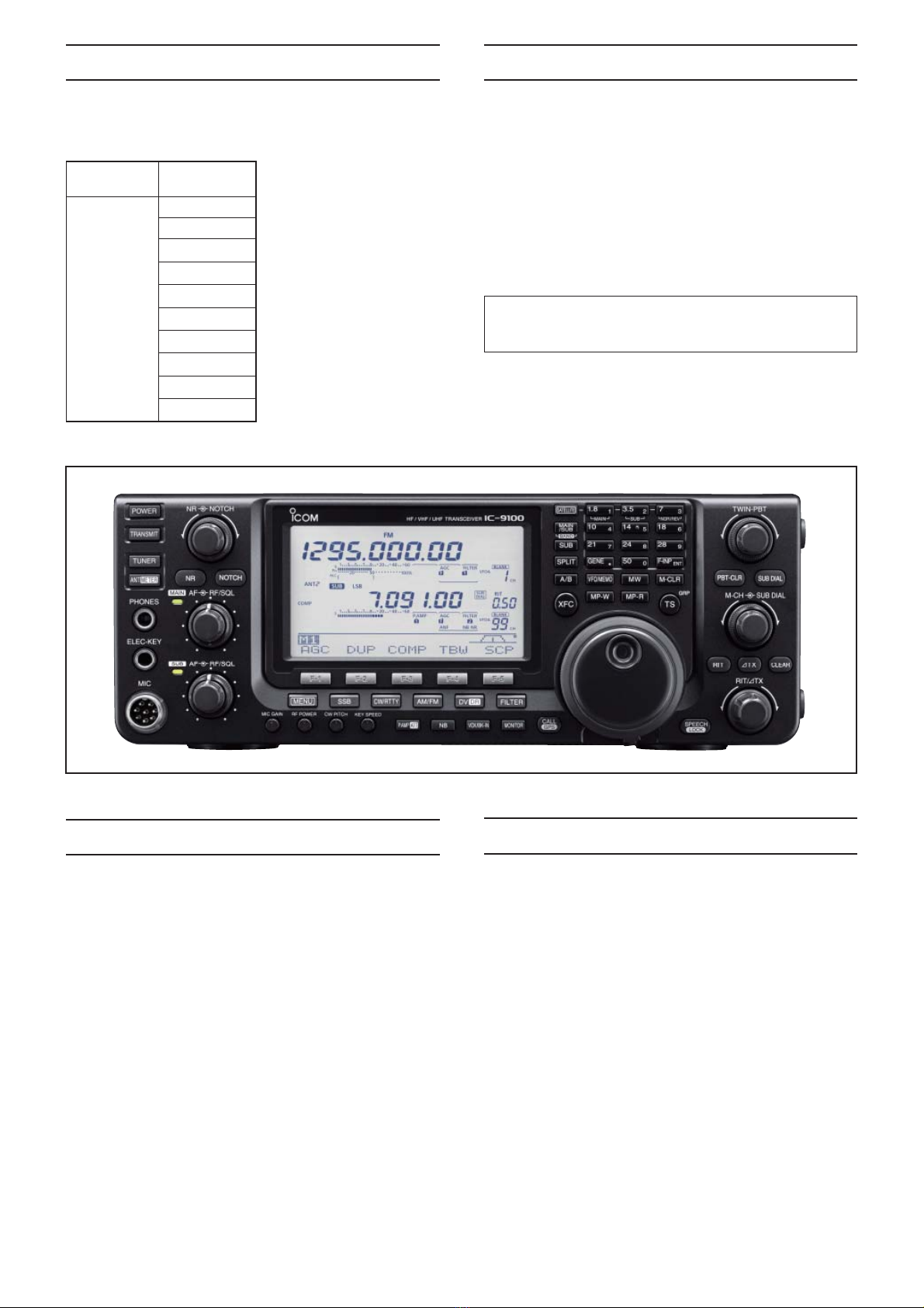
Icom IC-9100 User manual

S-14721XZ-C1
Jun. 2011
HF/VHF/UHF TRANSCEIVER

This service manual describes the latest technical
information for the IC-9100 HF/VHF/UHF TRANSCEIVER,
at the time of publication.
NEVER connect the transceiver to an AC outlet or to a DC
power supply that uses more than the specified voltage.
This will ruin the transceiver.
DO NOT expose the transceiver to rain, snow or any liquids.
DO NOT reverse the polarities of the power supply when
connecting the transceiver.
DO NOT apply an RF signal of more than 20 dBm (100 mW) to
the antenna connector. This could damage the transceiver’s
front-end.
To upgrade quality, any electrical or mechanical parts
and internal circuits are subject to change without notice
or obligation.
MODEL VERSION
IC-9100
[USA]
[EUR]
[EUR-01]
[ITR]
[ESP]
[TPE]
[KOR]
[CHN]
[FRA]
[EXP]
Be sure to include the following four points when ordering
replacement parts:
1. 10-digit Icom part number
2. Component name
3. Equipment model name and unit name
4. Quantity required
<ORDER EXAMPLE>
1110003491 S.IC TA31136FNG IC-9100 MAIN UNIT 5 pieces
8820001210 Screw 2438 screw IC-9100 Top cover 10 pieces
Addresses are provided on the inside back cover for your
convenience.
ORDERING PARTS
1. Make sure that the problem is internal before
disassembling the transceiver.
2. DO NOT open the transceiver until the transceiver is
disconnected from its power source.
3. DO NOT force any of the variable components. Turn
them slowly and smoothly.
4. DO NOT short any circuits or electronic parts. An
insulated tuning tool MUST be used for all adjustments.
5. DO NOT keep power ON for a long time when the
transceiver is defective.
6. DO NOT transmit power into a Standard Signal
Generator or a Sweep Generator.
7. ALWAYS connect a 50 dB to 60 dB attenuator between
the transceiver and a Deviation Meter or Spectrum
Analyzer, when using such test equipment.
8. READ the instructions of the test equipment throughly
before connecting it to the transceiver.
REPAIR NOTES
INTRODUCTION CAUTION
Icom, Icom Inc. and the Icom logo are registered trademarks of Icom Incorporated (Japan) in Japan, the United States, the
United Kingdom, Germany, France, Spain, Russia and/or other countries.

TABLE OF CONTENTS
SECTION 1 SPECIFICATIONS
SECTION 2 INSIDE VIEWS
SECTION 3 CIRCUIT DESCRIPITON
3-1 RECEIVER CIRCUITS. . . . . . . . . . . . . . . . . . . . . . . . . . . . . . . . . . . . . . . . . . . . . . . . . . . . . . . . 3-1
3-2 TRANSMITTER CIRCUITS . . . . . . . . . . . . . . . . . . . . . . . . . . . . . . . . . . . . . . . . . . . . . . . . . . . . 3-5
3-3 FREQUENCY SYNTHESIZER CIRCUITS . . . . . . . . . . . . . . . . . . . . . . . . . . . . . . . . . . . . . . . . 3-8
3-4 VOLTAGE DIAGRAMS. . . . . . . . . . . . . . . . . . . . . . . . . . . . . . . . . . . . . . . . . . . . . . . . . . . . . . . . 3-10
3-5 PORT ALLOCATIONS . . . . . . . . . . . . . . . . . . . . . . . . . . . . . . . . . . . . . . . . . . . . . . . . . . . . . . . . 3-10
SECTION 4 ADJUSTMENT PROCEDURES
4-1 PREPARATION . . . . . . . . . . . . . . . . . . . . . . . . . . . . . . . . . . . . . . . . . . . . . . . . . . . . . . . . . . . . . 4-1
4-2 ADJUSTMENTS ON THE PLL UNIT. . . . . . . . . . . . . . . . . . . . . . . . . . . . . . . . . . . . . . . . . . . . . 4-2
4-3 ADJUSTMENT ON THE MAIN UNIT. . . . . . . . . . . . . . . . . . . . . . . . . . . . . . . . . . . . . . . . . . . . . 4-5
4-4 ADJUSTMENT ON THE PA-B UNIT . . . . . . . . . . . . . . . . . . . . . . . . . . . . . . . . . . . . . . . . . . . . . 4-5
4-5 ADJUSTMENTS ON THE RF-A UNIT. . . . . . . . . . . . . . . . . . . . . . . . . . . . . . . . . . . . . . . . . . . . 4-6
4-6 ADJUSTMENTS ON THE RF-B UNIT. . . . . . . . . . . . . . . . . . . . . . . . . . . . . . . . . . . . . . . . . . . . 4-8
4-7 ADJUSTMENT ON THE CTRL UNIT . . . . . . . . . . . . . . . . . . . . . . . . . . . . . . . . . . . . . . . . . . . . 4-10
4-8 ADJUSTMENTS ON THE FUNCTION DISPLAY . . . . . . . . . . . . . . . . . . . . . . . . . . . . . . . . . . . 4-11
SECTION 5 PARTS LIST
SECTION 6 MECHANICAL PARTS
SECTION 7 BOARD LAYOUTS
DISPLAY BOARD AND DC-DC UNIT . . . . . . . . . . . . . . . . . . . . . . . . . . . . . . . . . . . . . . . . . . . . 7-1
PLL UNIT . . . . . . . . . . . . . . . . . . . . . . . . . . . . . . . . . . . . . . . . . . . . . . . . . . . . . . . . . . . . . . . . . . 7-3
MAIN UNIT. . . . . . . . . . . . . . . . . . . . . . . . . . . . . . . . . . . . . . . . . . . . . . . . . . . . . . . . . . . . . . . . . 7-5
CONNECT UNIT . . . . . . . . . . . . . . . . . . . . . . . . . . . . . . . . . . . . . . . . . . . . . . . . . . . . . . . . . . . . 7-7
PA-A UNIT . . . . . . . . . . . . . . . . . . . . . . . . . . . . . . . . . . . . . . . . . . . . . . . . . . . . . . . . . . . . . . . . . 7-9
PA-B UNIT . . . . . . . . . . . . . . . . . . . . . . . . . . . . . . . . . . . . . . . . . . . . . . . . . . . . . . . . . . . . . . . . . 7-11
NETWORK UNIT . . . . . . . . . . . . . . . . . . . . . . . . . . . . . . . . . . . . . . . . . . . . . . . . . . . . . . . . . . . . 7-13
CTRL UNIT . . . . . . . . . . . . . . . . . . . . . . . . . . . . . . . . . . . . . . . . . . . . . . . . . . . . . . . . . . . . . . . . 7-15
BPF, JACK, MIC, VR-A/B/C, M-CH AND RIT UNITS . . . . . . . . . . . . . . . . . . . . . . . . . . . . . . . . 7-17
RF-A UNIT . . . . . . . . . . . . . . . . . . . . . . . . . . . . . . . . . . . . . . . . . . . . . . . . . . . . . . . . . . . . . . . . . 7-19
RF-B UNIT . . . . . . . . . . . . . . . . . . . . . . . . . . . . . . . . . . . . . . . . . . . . . . . . . . . . . . . . . . . . . . . . . 7-21
SECTION 8 WIRING DIAGRAM
SECTION 9 BLOCK DIAGRAM
SECTION 10 VOLTAGE DIAGRAM
DISPLAY BOARD . . . . . . . . . . . . . . . . . . . . . . . . . . . . . . . . . . . . . . . . . . . . . . . . . . . . . . . . . . . 10-1
CONNECT UNIT . . . . . . . . . . . . . . . . . . . . . . . . . . . . . . . . . . . . . . . . . . . . . . . . . . . . . . . . . . . . 10-3
MAIN UNIT. . . . . . . . . . . . . . . . . . . . . . . . . . . . . . . . . . . . . . . . . . . . . . . . . . . . . . . . . . . . . . . . . 10-6
RF-A UNIT . . . . . . . . . . . . . . . . . . . . . . . . . . . . . . . . . . . . . . . . . . . . . . . . . . . . . . . . . . . . . . . . . 10-12
RF-B UNIT . . . . . . . . . . . . . . . . . . . . . . . . . . . . . . . . . . . . . . . . . . . . . . . . . . . . . . . . . . . . . . . . . 10-14
BPF UNIT. . . . . . . . . . . . . . . . . . . . . . . . . . . . . . . . . . . . . . . . . . . . . . . . . . . . . . . . . . . . . . . . . . 10-18
PA-A UNIT . . . . . . . . . . . . . . . . . . . . . . . . . . . . . . . . . . . . . . . . . . . . . . . . . . . . . . . . . . . . . . . . . 10-18
PA-B UNIT . . . . . . . . . . . . . . . . . . . . . . . . . . . . . . . . . . . . . . . . . . . . . . . . . . . . . . . . . . . . . . . . . 10-20
CTRL UNIT . . . . . . . . . . . . . . . . . . . . . . . . . . . . . . . . . . . . . . . . . . . . . . . . . . . . . . . . . . . . . . . . 10-22
DC-DC UNIT . . . . . . . . . . . . . . . . . . . . . . . . . . . . . . . . . . . . . . . . . . . . . . . . . . . . . . . . . . . . . . . 10-23
NETWORK UNIT . . . . . . . . . . . . . . . . . . . . . . . . . . . . . . . . . . . . . . . . . . . . . . . . . . . . . . . . . . . . 10-24
PLL UNIT . . . . . . . . . . . . . . . . . . . . . . . . . . . . . . . . . . . . . . . . . . . . . . . . . . . . . . . . . . . . . . . . . . 10-25

1 - 1
SECTION 1
.
SPECIFICATIONS
■General
• Frequency coverage : (unit: MHz)
Receive
0.030–60.000*1*2
136.000–174.000*1*2
420.000–480.000*1*2
1240.000–1320.000†
Transmit
1.800–1.999*2, 3.500–3.999*2,
5.330500*3, 5.346500*3, 5.366500*3,
5.371500*3, 5.403500*3,
7.000–7.300*2, 10.100–10.150*2,
14.000–14.350*2, 18.068–18.168*2,
21.000–21.450*2, 24.890–24.990*2,
28.000–29.700*2,50.000–54.000*2
144.000–148.000*2,430.000–450.000*2
1240.000–1300.000†
*
1Some frequency bands are not guaranteed.
*
2Depending on version.
*
3
USA version only. USB mode only.
• Mode : USB, LSB, CW, RTTY, AM, FM,
DV*
*The optional UT-121 is required.
• No. of memory channels : 297CH (99CH × 3 band)
(
396CH with UX-9100‡; 99CH × 4
bands)
• No. of scan edge
memory channels : 18CH (6 × 3 band)
(24CH with UX-9100‡; 6CH × 4
bands)
• No. of call channels : 3CH (1 × 3 band)
(4CH with UX-9100‡; 1CH × 4
bands)
• No. of Satellite
memory channels : 20CH
• Antenna connector : SO-239 ×3
Type-N ×2*
*When the optional UX-9100 is installed.
• Antenna impedance :
50 Ω
(at Antenna Tuner OFF)
•
Usable temperature range
:
0˚C to +50˚C (+32˚F to +122˚F)
• Frequency stability : Less than ±0.5 ppm 5 min. after
power ON.
(0˚C to +50˚C; +32˚F to
+122˚F)
• Frequency resolution : 1 Hz
• Power supply :
13.8 V DC ±15% (negative ground)
• Power consumption
Transmit
Max. power : 24.0 A (HF/50/144/430 MHz band)
11.0 A (1200 MHz band)†
Receive
Standby : 3.0 A (HF/50/144/430 MHz band)
4.0 A (1200 MHz band)†
Max. audio : 4.5 A (HF/50/144/430 MHz band)
5.5 A (1200 MHz band)†
• Dimensions :
315(W) ×116(H) ×343(D) mm
(projections not included) 12.4(W) ×4.57(H) ×13.5(D) in
• Weight (approximately) : 11.0 kg; 24.2 lb
11.95 kg; 26.3 lb (with UX-9100)
• ACC connector : 13-pin
• CI-V connector : 2-conductor 3.5 (d) mm (1⁄8″)
■Transmitter
• Output power (continuously adjustable)
Frequency band Output power
HF/50 MHz 2 to 100 W (AM: 2 to 30 W)*
144 MHz 2 to 100 W
430 MHz 2 to 75 W
1200 MHz†1 to 10 W
(at 13.8 V DC/+25˚C)
* In the AM mode, transmission can be performed only on
the HF/50 MHz frequency band.
• Modulation system
SSB : Digital PSN modulation
AM : Digital Low power modulation
FM : Digital Phase modulation
DV* :
GMSK Digital Phase modulation
*The optional UT-121 is required.
• Spurious emission
(Spurious domain)
HF bands : Less than –50 dB
50/144 MHz band : Less than –63 dB
430 MHz band : Less than –61.8 dB
1200 MHz band†: Less than –53 dB
(Out-of-band domain)
HF bands : Less than –40 dB
50/144/430 MHz band: Less than –60 dB
1200 MHz band†: Less than –50 dB
• Carrier suppression : More than 40 dB
• Unwanted sideband
suppression : More than 55 dB
(1200 MHz: More than 40 dB)†
• TX variable range : ±9.999 kHz
• Microphone connector : 8-pin connector
• Microphone impedance : 600
Ω
• ELEC-KEY connector :
3-conductor 6.35(d) mm
(1⁄4″)
• KEY connector :
3-conductor 6.35(d) mm
(1⁄4″)
• SEND connector : Phono jack (RCA)
• ALC connector : Phono jack (RCA)
†The optional UX-9100 is required for 1200 MHz frequency band operation.
‡Only when the 1200 MHz frequency band is selected.

1 - 2
■Receiver
• Receive system
HF/50/144/430 MHz band
:
Double superheterodyne system
1200 MHz band†: Triple superheterodyne system
• Intermediate frequencies
1st : 64.455 MHz (HF/50 MHz band)
10.850 MHz (144 MHz band)
71.250 MHz (430 MHz band)
243.950 MHz (1200 MHz band)†
2nd : 36 kHz (HF/50/144/430 MHz)
10.950 MHz (1200 MHz)†
3rd : 36 kHz (1200 MHz)†
• Sensitivity
SSB, CW : 0.16 µV (1.80–29.99 MHz)*1
(10 dB S/N) BW=2.4 kHz 0.13 µV (50.0–54.0 MHz)*2
0.11 µV (144/430/1200†MHz)
AM (10 dB S/N) : 12.6 µV (0.5–1.799 MHz)*1
BW=6 kHz 2.0 µV (1.80–29.99 MHz)*1
1.6 µV (50.0–54.0 MHz)*2
1.4 µV (144/430 MHz)
FM (12 dB SINAD) : 0.5 µV (28.0–29.7 MHz)*1
BW=15 kHz 0.32 µV (50.0–54.0 MHz)*2
0.18 µV (144/430/1200†MHz)
DV (1% BER) : 1.0 µV (28.0–29.7 MHz)*1
CH Space=12.5 kHz 0.63 µV (50.0–54.0 MHz)*2
0.35 µV (144/430/1200†MHz)
• Squelch sensitivity
Frequency band Squelch sensitivity
HF SSB : Less than 5.6 µV*1
FM : Less than 0.3 µV*1
50 MHz SSB : Less than 5.6 µV*2
FM : Less than 0.3 µV*2
144/430 MHz SSB : Less than 1.0 µV
FM : Less than 0.18 µV
1200 MHz†SSB : Less than 1.0 µV
FM : Less than 0.18 µV
*1Preamp 1 is ON. *2Preamp 2 is ON.
• Selectivity
(IF filter shape is set to SHARP.)
SSB (BW: 2.4 kHz) : More than 2.4 kHz/–6 dB
Less than 3.4 kHz/–40 dB
CW (BW: 500 Hz) : More than 500 Hz/–6 dB
Less than 700 Hz/–40 dB
RTTY (BW: 500 Hz) : More than 500 Hz/–6 dB
Less than 800 Hz/–40 dB
AM (BW: 6 kHz) : More than 6.0 kHz/–6 dB
Less than 10.0 kHz/–40 dB
FM (BW: 15 kHz) : More than 12.0 kHz/–6 dB
Less than 22.0 kHz/–40 dB
DV
(CH space: 12.5 kHz)
: More than –50 dB
• Spurious and image rejection ratio
HF/50 MHz band* : More than 70 dB
*except IF through on 50 MHz band
144/430 MHz band : More than 60 dB
1200 MHz band†: More than 50 dB
• AF output power : More than 2.0 W at 10%
(at 13.8 V DC) distortion with an 8
Ω
load
• AF output impedance : 8
Ω
• RIT variable range : ±9.999 kHz
• PHONES connector : 3-conductor 6.35 (d) mm (1⁄4″)
• External SP connector : 2-conductor 3.5 (d) mm
(1⁄8″)/8
Ω
• DSP ANF attenuation : More than 30 dB
(with 1 kHz single tone)
• DSP MNF attenuation : More than 70 dB
• DSP NR attenuation : More than 6 dB
(noise rejection in SSB)
■Antenna tuner
• Matching impedance range
HF bands : 16.7 to 150
Ω
unbalanced
(Less than VSWR 1:3)
50 MHz band : 20 to 125
Ω
unbalanced
(Less than VSWR 1:2.5)
• Minimum operating input : 8 W (HF bands)
power 15 W (50MHz band )
• Tuning accuracy : VSWR 1:1.5 or less
• Insertion loss : Less than 1.0 dB
(after tuning at RF power 100 W)
All stated specifications are typical and subject to change without notice or obligation.

2 - 1
SECTION 2
.
INSIDE VIEWS
RF-B UNIT
PA-B UNIT
PA-A UNIT
NETWORK UNIT
CONNECT UNIT
PLL UNIT
BPF UNIT
VARIABLE
CAPACITORS
• THE VIEW FROM THE BOTTOM OF CHASSIS
• THE VIEW FROM THE TOP OF CHASSIS

2 - 2
DC-DC CONVERTER
(IC2001)
• MAIN UNIT
(TOP VIEW)
BUFFER
(IC4405)
DSP
(IC4001)
LPF
(IC4402)
UT-121
(Optional product)
CMOS BUFFER
(IC6101)
CPLD
(IC1261)
LPF
(IC4404)
LPF
(IC4403)
BUFFER
(IC4401)
EEPROM
(IC4202)
CODEC
(IC4461)
BUFFER
(IC4483)
BUFFER
(IC4482)
LPF
(IC3453)
BUFFER
(IC4481)

2 - 3
DSP
(IC5001)
• MAIN UNIT
(BOTTOM VIEW)
BUFFER
(IC4661)
LPF
(IC4603)
CODEC
(IC5451)
BUFFER
(IC4601)
LPF
(IC5405)
BUFFER
(IC5482)
CMOS BUFFER
(IC6102)
ANALOG SW
(IC6002)
ANALOG SW
(IC3504)
+5 V REGULATOR
(IC2101)
LPF
(IC3601)
APC
(IC3271)
ID DETECTER
(IC3251)
S/P CONVERTER
(IC3204)
CMOS SW
(IC1162)
CPU
(IC1201)
EEPROM
(IC1081)
CMOSS BUFFER
(IC6103)
CODEC
(IC5452)
CODEC
(IC4651)
ANALOG SW
(IC3503)
BUFFER
(IC4602)
AGC DET
(IC3522)
ANALOG SW
(IC3518)
S/P CONVERTER
(IC3202)
ANALOG SW
(IC6001)
CMOS SW
(IC1161)
S/P CONVERTER
(IC3201)
ANALOG SW
(IC3506)
BUFFER
(IC1163)
VCA
(IC3401)
ANALOG SW
(IC3421)
ANALOG SW
(IC3422)
AF AMP
(IC3452)
ANALOG SW
(IC3517)
S/P CONVERTER
(IC3203)

2 - 4
2ND RX IF MIXER (VHF BAND)
(D251, D255)
1ST RX IF MIXER (VHF BAND)
• RF-B UNIT
TX POWER SUPPLY LINE SW
(Q35)
RX POWER SUPPLY LINE SW
(Q32)
D/A CONVERTER
(IC1)
DC AMP
(IC71)
1ST RX IF AMP (UHF BAND)
(Q2021)
1ST RX IF FILTER (UHF BAND)
(FI731)
1ST RX IF FILTER (VHF BAND)
(FI331A/B)
1ST RX IF AMP (VHF BAND)
(Q1021)
RF AMP (VHF BAND)
(IC2651)
1ST RX IF MIXER (UHF BAND) 2ND RX IF MIXER (UHF BAND)
(D251, D255)

2 - 5
• PLL UNIT
DDS-A
(IC702)
DDS-B
(IC1502)
SERIAL-PARALLEL
CONVERTER
(IC1402)
ANALOG SW
(IC1454)
DDS B
(IC1051)
32 MHz REFERENCE
FREQUENCY
OSCILLATOR
(X151)
PLL IC
(IC201)
LEVEL CONVERTOR
(IC1054)
PROGRAMMABLE CLOCK GENERATOR
(IC662)
ANALOG SW
(IC1455)
LEVEL CONVERTOR
(IC1053)
1ST TX/RX LO FILTER
(FI401)
SERIAL-PARALLEL
CONVERTER
(IC104)
SERIAL-PARALLEL
CONVERTER
(IC1401)
SERIAL-PARALLEL
CONVERTER
(IC103)

2 - 6
DC-DC CONVERTER
(IC131)
• PA-A UNIT
D/A CONVERTER
(IC431)
S/P CONVERTER
(IC432)
DRIVE AMP
(Q221)
DC AMP
(IC371)
BIAS CONTROLLER
(IC301)
DRIVE AMP
(Q222)
POWER AMP
(Q241)
POWER AMP
(Q242)
PRE-DRIVE AMP
(Q201)

2 - 7
• PA-B UNIT
POWER AMP (VHF BAND)
(Q702)
YGR AMP
(Q171)
PRE-DRIVE AMP
(Q201)
POWER AMP (UHF BAND)
(Q401)
POWER AMP (VHF BAND)
(Q701)
POWER AMP (UHF BAND)
(Q402)
+12 V REGULATOR
(IC841)
POWER AMP (UHF BAND)
BIAS CONTROLLER
(IC552)
D/A CONVERTER
(IC931)
POWER AMP (UHF BAND)
BIAS CONTROLLER
(IC551)
DRIVE AMP
(Q251)

2 - 8
TUNER CPU
(IC701)
• CTRL UNIT
DC AMP
(IC131)
+5 V REGULATOR
(IC801)
DC AMP
(IC41)
PHASE DETECTOR
(IC111)
ANTENNA SW
(RL501)

2 - 9
• CONNECT UNIT
MULTIPLEXER
(IC1211)
USB BRIDGE
(IC901)
AF AMP
(IC502)
MULTIPLEXER
(IC541)
USB CODEC
(IC551)
AF LPF/TONE FILTER
(IC281)
BUFFER
(IC221)
SEND CONTROLLER
(Q1412)
USB HUB
(IC902)
SERIAL-PARALLEL
CONVERTER
(IC21)
AF AMP/DC AMP
(IC401)
COOLING FAN DRIVER
(Q151)
SERIAL-PARALLEL
CONVERTER
(IC22)
D/A CONVERTER
(IC151)
BUFFER
(IC501)
MULTIPLEXER
(IC201)
VCA
(IC301)
BUFFER
(IC251)
USB BRIDGE
(IC903)
LEVEL CONVERTER
(IC821)

2 - 10
• BPF UNIT
PRE-AMP
(Q511, Q512)
PRE-AMP
(Q532)
YGR AMP (HF BAND)
(IC201)

3-1 RECEIVER CIRCUITS
HF RF CIRCUITS
ANTENNA SWITCHING CIRCUITS (CTRL UNIT)
RX signal from the antenna connector [ANT1] (J1) or [ANT2]
(J2) is passed through the antenna switch (RL501), current
detector (D401, L401), tuner switches (RL301 and RL351),
RX line switches (RL601 and RL621) and LPF, and then
applied to the BPF UNIT.
ATTENUATOR CIRCUITS (BPF UNIT)
The RX signal from the CTRL UNIT is passed through
or bypassed the attenuator circuit (RL141, R141–R143),
depending on the setting.
The RX signal, which is passed though or bypassed the
attenuator circuit (RL141, R141–R143), is applied to the
BPF circuits.
BPF CIRCUITS (BPF UNIT)
The RX signal from the attenuator circuits is passed
through an LPF or one of BPFs, depending on the operating
frequency, to remove unwanted out-of-band signals.
The filtered RX signal is applied to or bypassed the
preamplifier circuits.
PREAMPLIFIER CIRCUITS (BPF UNIT)
The RX signal from the BPF circuits is applied to or
bypassed the preamplifier.
When the Preamplifier function is activated, the RX signal is
amplified by one of preamplifiers (Q511, Q512 (for 1.8–2.1 MHz)
or Q532 (for 24–50 MHz)).
The amplified or bypassed RX signal is applied to the RF-A
UNIT.
3 - 1
SECTION 3
.
CIRCUIT DESCRIPTION
CURRENT
DET
D401
TUNING
NETWORK
LPF
HF ANT1 HF ANT2
BPF
BPF
BPF
BPF
BPF
BPF
RL141
BPF
HPF
BPF
ATTLPF
BPF
PRE
AMP
Q511/Q512
To the 1st RX IF circuits
PRE
AMP
Q532
RL601
RL621
RL301
CTRL UNIT
RL501
RL351
1.6-2.0 MHz
4.0-8.0 MHz
50.0-54.0 MHz
30.0-50.0 MHz
11.0-15.0 MHz
8.0-11.0 MHz
54.0-60.0 MHz
2.0-4.0 MHz
15.0-22.0 MHz
22.0-30.0 MHz
BPF UNIT
0.03-1.6 MHz
NETWORK
UNIT
• HF RF CIRCUITS

3 - 2
VHF ANT
UHF ANT
LPF
LPF
TX/RX
SW
L407CD
TX/RX
SW
RL751
To the VHF TX Circuits
UHF TX Circuits
SWR
DET
D801/D811
SWR
DET
D501/D511
LPF
PA-B UNIT
BPF
PRE
AMP
Q1251
D1352-D1354,
D1351
ATT
BPF BPF
BPF
ATT
VRX HPF
HPF
HPF
RF
AMP
IC2251 D2351-D2354
RF-B UNIT
To the VHF 1st RX IF circuits
To the UHF 1st RX IF circuits
URX
VHF RF CIRCUITS (RF-B UNIT)
VHF band RX signal from the antenna connector [144MHz
ANT] (CHASSIS; J1) is passed through the SWR detecter
(PA-B; D801, D811), LPF (PA-B; L771–L773, C771–C777),
TX/RX SW (PA-B; RL751) and LPF (PA-B; L763, C770), and
then applied to the RF-B UNIT.
The RX signal from the PA-B UNIT is passed through the
HPF (L1353, L1354, C1355–C1357), and then passed
through or bypassed the attenuator circuit (D1351–D1354,
R1352–R1354), depending on the setting.
The RX signal, which is passed though or bypassed the
attenuator circuit (D1351–D1354, R1352–R1354), is passed
through the BPF (D1301, D1302, L1301, L1302, C1301,
C1302), and then applied to the RF AMP (Q1251).
The amplified RX signal is passed through the two-
staged BPF (D1209–D1211, L1202, C1203, C1206,
and D1202–D1204, L1201, C1201, C1205) and HPF
(L1111–L1114, C1111–C1114, C1116–C1117, C1119), and
then applied to the 1st RX IF circuits.
UHF RF CIRCUITS (RF-B UNIT)
UHF band RX signal from the antenna connector [430MHz
ANT] (CHASSIS; J2) is passed through the SWR detecter
(PA-B; D501, D511), LPF (L451, L452, C451–C455), TX/
RX SW (PA-B; D471–D473) and LPF (L471, C471, C472,
C475), and then applied to the RF-B UNIT.
The RX signal from the PA-B UNIT is passed through the HPF
(L2361, L2362, C2361–C2363, C2359), and then passed
through or bypassed the attenuator circuit (D2351–D2354,
R2352, R2354, R2355), depending on the setting.
The RX signal, which is passed though or bypassed the
attenuator circuit (D2351–D2354, R2352, R2354, R2355),
is passed through the BPF (D2301, D2302, L2301, C2301,
C2302), and then applied to the RF AMP (Q2251).
The amplified RX signal is passed through the two-
staged BPF (D2201–D2203, L2204, C2202, C2204, and
D2204–D2206, L2205, C2205, C2206) and HPF (L2210,
C2210), and then applied to the 1st RX IF circuits.
IF
AMP
IC1221
BUFF
Q1251
IF
AMP
IC1221
Σ
IC1222
To the demodulator circuits
IF
AMP
Q1051
BUFF
Q1201
D1101
IF
AMP
Q1071/Q1072
D1102
90deg
IC1222
Q721/Q722/
Q723/Q724
IF
AMP
Q741
BPF
XTAL
64.455MHz(BW=3kHz)
BPF
XTAL
64.455MHz(BW=15kHz)
FI911
ATT
BPF
XTAL
64.455MHz(BW=6kHz)
FL-430(Optional)
FL-431(Optional)
LPF
fc=60MHz
LO
AMP
Q811
LPF
BUFF
IC1121
BUFF
IC1121
LO
AMP
Q1141
2nd RX LO
1st RX/TX LO
BUFF
IC1121
From the preamplifier circuits
90deg
ATT
LPF
LPF
RF-A UNIT
64.485~
124.455 MHz
from PLL UNIT
from PLL UNIT
HF 1ST RX IF CIRCUITS (RF-A UNIT)
The RX signal from the BPF UNIT is passed through the
LPF, which removes unwanted signals (60 MHz and higher),
and then applied to the 1st RX IF mixer (Q721–Q724) to be
mixed with the 1st RX LO signal (64.485–124.455 MHz) from
the PLL UNIT, resulting in the 64.455 MHz 1st RX IF signal.
The 1st RX IF signal is amplified by the 1st RX IF AMP
(Q741) and passed through one of the 1st IF filters (FI911;
FL-434, or optional FL-430 or FL-431), which has different
passband widths, according to the IF filter setting.
The filtered 1st RX IF signal is amplified by the RX IF AMPs
(Q1051 and Q1071, Q1072), and then applied to the 2nd RX
IF circuits.
HF 2ND RX IF CIRCUITS (RF-A UNIT)
The 1st RX IF signal from the 1st RX IF circuits is divided
into two paths, and then each signal is applied to the 2nd RX
IF mixers (the image reduction mixers; D1102/D1101) to be
mixed with the 2nd RX LO signal (64.491 MHz) from the PLL
UNIT, resulting in the 36 kHz 2nd RX IF signal.
The image reduction mixer removes image frequency
components by using two LO signals which are 90 degrees
phase-shifted from each other.
The 2nd RX IF signals are independently amplified by the
buffers (Q1201/Q1251) and IF AMPs (IC1221).
These amplified 2nd RX IF signals are 90 degrees phase-
shifted and combined by the combiner (IC1222), and then
applied to the MAIN UNIT.
• VHF/UHF RF CIRCUITS
• HF 1ST RX IF AND 2ND RX IF CIRCUITS

Q1051/Q1052/
Q1053/Q1054
LO
AMP
Q1471
LO
AMP
Q2471
Q2051/2052
U1Lo
BPF
XTAL
71.25 MHz
FI731
LO
AMP
Q601
90deg
IC501
IF
AM P
IC521
IF
AM P
Q701/Q702
D651
IF
AM P
IC521
90degBUFF
IC611 BUFF
IC611
BUFF
Q551
D655
Σ
IC501
BUFF
IC611
IF
AMP
Q711
BUFF
Q541
UR2Lo
IF
AMP
IC121
VR2Lo
D255
BUFF
IC211
BUFF
IC211
IF
AM P
Q301/302
IF
AM P
Q311
BUFF
IC211
D251
BUFF
Q141
90deg
LO
AMP
Q201
BUFF
Q151
IF
AMP
IC121
BPF
XTAL
10.85 MHz
FI331
URIF
HPF
LPF HPF
ATT
HPF
HPF
LPF
90deg
IC101
Σ
IC101
VRI F
V1Lo
IF
AMP
Q1021
IF
AMP
Q2021
LPF
BPF
LO
AMP
IC2582
BPF
71.214 MHz
10.814 MHz
125.15~
163.15 MHz
From the VHF RF circuits
From the UHF RF circuits
from PLL UNIT
To MAIN UNIT
from PLL UNIT
from PLL UNIT
To MAIN UNIT
from PLL UNIT
3 - 3
VHF 1ST RX IF CIRCUITS (RF-B UNIT)
The RX signal from the RF circuits is applied to the 1st RX IF
mixer (Q1051–Q1054) to be mixed with the 1st RX LO signal
(125.15–163.15 MHz) from the PLL UNIT, resulting in the
10.85 MHz 1st RX IF signal.
The 1st RX IF signal is passed through the 1st IF filter
(FI331), amplified by two 1st RX OF AMPs (Q301, Q302 and
Q311), and then applied to the 2nd RX IF circuits.
UHF 1ST RX IF CIRCUITS (RF-B UNIT)
The RX signal from the RF circuits is applied to the 1st RX IF
mixer (Q2051, Q2052) to be mixed with the 1st RX LO signal
(348.75–408.75 MHz) from the PLL UNIT, resulting in the
71.25 MHz 1st RX IF signal.
The 1st RX IF signal is amplified by the 1st RX IF AMP
(Q2021), passed through the 1st IF filter (FI731), and then
amplified by two 1st RX IF AMPs (Q701, Q702 and Q711).
The amplified 1st RX IF signal is applied to the 2nd RX IF
circuits.
VHF 2ND RX IF CIRCUITS (RF-B UNIT)
The 1st RX IF signal from the 1st RX IF circuits is divided
into two paths, and then each signal is applied to the 2nd
RX IF mixers (the image reduction mixers; D251/D255) to be
mixed with the 2nd RX LO signal (10.814 MHz) from the PLL
UNIT, resulting in the 36 kHz 2nd RX IF signal.
The image reduction mixer removes image frequency
components by using two LO signals which are 90 degrees
phase-shifted from each other.
The 2nd RX IF signals are independently amplified by the
buffers (Q151/Q141) and IF AMPs (IC121).
These amplified 2nd RX IF signals are 90 degrees phase-
shifted and combined by the combiner (IC101), and then
applied to the MAIN UNIT.
UHF 2ND RX IF CIRCUITS (RF-B UNIT)
The 1st RX IF signal from the 1st RX IF circuits is divided
into two paths, and then each signal is applied to the 2nd
RX IF mixers (the image reduction mixers; D651/D655) to be
mixed with the 2nd RX LO signal (71.214 MHz) from the PLL
UNIT, resulting in the 36 kHz 2nd RX IF signal.
The image reduction mixer removes image frequency
components by using two LO signals which are 90 degrees
phase-shifted from each other.
The 2nd RX IF signals are independently amplified by the
buffers (Q551/Q541) and IF AMPs (IC521).
These amplified 2nd RX IF signals are 90 degrees phase-
shifted and combined by the combiner (IC501), and then
applied to the MAIN UNIT.
• VHF/UHF 1ST RX IF AND 2ND IF CIRCUITS

DEMODULATOR CIRCUITS (MAIN UNIT)
The 2nd RX IF signal from the 2nd RX IF circuits is passed
through the MAIN/SUB BAND SW (HF band; IC3501, VHF
band; IC3502, UHF band; IC3503), and then applied to the
demodulator circuits.
• MAIN BAND
The 2nd RX IF signal is passed through the AF SW (HF
band; IC3510, VHF band; IC3514, UHF band; IC3518), RX
mute SW (IC4604) and the balance-unbalance converter
(Balun; IC4602/IC4603), and then applied to the CODEC
(IC4651) to be converted into digital audio signal.
The converted digital audio signal is applied to the MAIN
DSP (IC4001), and demodulated and processed.
The demodulated signal is applied to another CODEC
(IC4461) to be converted into analog AF signal, and then
applied to the buffer amplifier (IC4483).
The buffer amplified AF signal is applied to the CONNECT UNIT.
3 - 4
AMP
IC4483
BUFF
IC4602
MUTE
IC4604
LPF
IC4603
LPF
IC4603
IC1201 IC1261
MAIN
CPU CPLD
MAIN BAND PATH
SUB BAND PATH
CODEC
IC4461 IC4001
DSP
From the 2nd RX circuits
To the MAIN RX AF circuits
CODEC
IC4651
AMP
IC5481
CODEC
IC5451 IC5001
DSP
To the SUB RX AF circuits
CODEC
IC5451
VRIF
URIF
HRIF
IC3502
IC3503
IC3501
IC3514
IC35013
IC3518
IC3517
IC3509
IC3510
MAIN UNIT
MDRIF
From RF-B UNIT
From RF-B UNIT
From RF-A UNIT
MUTE
IC5404
BUFF
IC5402
LPF
IC5403
SDRIF
LPF
IC5403
From the modulator circuits
SP1
Internal
speaker
[MAIN EXT-SP]
[SUB EXT-SP]
VCA
AMP
IC301
IC201
SQL
GATE
Q221
AMP
SQL
GATE
Q231
Q321
SEL
SW
Q331
SEL
SW
IC201
AF
AM P
AF
AM P
IC351
RL361
VCA
RL371
AMP
IC221
AMP
IC221
BUFF
Q343
BUFF
Q344
IC341
IC342
J101
J102
RL372
SDRAF
MDRAF
CONNECT UNIT
J2(JACK UNIT)
[PHONES]
RX AF CIRCUITS (CONNECT UNIT)
• MAIN BAND
The AF signal from the demodulator circuits is applied to
the AF AMP (IC221), through the squelch gate (Q231).
The amplified AF signal is applied to the Voltage Controlled
Amplifier (VCA; IC301) to be adjusted in level (=audio output
level), through the AF SW (IC201) which toggles the AF
output lines for MAIN and SUB bands.
The level-adjusted AF signal is applied to the AF power AMP
(IC351), through the mute SW (Q321) and the buffer (Q343).
The amplified AF signal is passed through the AF mute
switch (RL361), and then applied to the internal speaker
through RL372, or external speaker jack ([MAIN EXT-
SP]; J101), or the amplified AF signal is applied to the
headphones jack (JACK BORD: J2).
• SUB BAND
The 2nd RX IF signal is passed through the AF SW (HF
band; IC3509, VHF band; IC3513, UHF band; IC3517), RX
mute SW (IC5404) and the balance-unbalance converter
(Balun; IC5402/IC5403), and then applied to the CODEC
(IC5451) to be converted into digital audio signal.
The converted digital audio signal is applied to the SUB DSP
(IC5001), and demodulated and processed.
The demodulated signal is applied to the CODEC (IC5481)
again, to be converted into analog AF signal, and then
applied to the buffer amplifier (IC5481).
The buffer amplified AF signal is applied to the CONNECT UNIT.
• SUB BAND
The AF signal from the demodulator circuits is applied to
the AF AMP (IC221), through the squelch gate (Q221).
The amplified AF signal is applied to the Voltage Controlled
Amplifier (VCA; IC301) to be adjusted in level (=audio output
level), through the AF SW (IC201) which toggles the AF
output lines for MAIN and SUB bands.
The level-adjusted AF signal is applied to the AF power AMP
(IC351), through the mute SW (Q331), the buffer (Q344) and
AF line SWs (IC341 and IC342), which selects the AF output
destinations from [MAIN EXT-SP] and [SUB EXT-SP].
The amplified AF signal is passed through the AF mute
switch (RL371), and then applied to the internal speaker
through RL372, or external speaker jack ([SUB EXT-
SP]; J101), or the amplified AF signal is applied to the
headphones jack (JACK BORD: J2).
• DEMODULATOR CIRCUITS
• RX AF CIRCUITS

3-2 TRANSMITTER CIRCUITS
TX AF CIRCUITS (MAIN UNIT)
The audio signal from the microphone (MIC signal) is
applied to the MAIN UNIT, through the MICROPHONE
CONNECTOR (MIC BOARD; J1), and then applied to the
Voltage Controlled Amplifier (VCA; IC3401).
The applied MIC signal is amplified by the MIC AMP, and
adjusted in level (=MIC gain) by the VCA circuit.
The level-adjusted MIC signal is passed through the MIC line
SW (IC3421), amplified by the AF AMP (IC3452), and then
applied to the modulation circuits, through the LPF (IC3452)
and MIC line SWs (IC3422 and IC3451).
The MIC signal from the accessory socket [ACC1] on the
rear panel, is directly applied to the AF AMP (IC3452),
through the MIC line SW (IC3421).
The amplified MIC signal is applied to the modulation
circuits.
MODULATION CIRCUITS (MAIN UNIT)
The MIC signal from the TX AF circuits is passed through
the Balance-Unbalance converter (Balun; IC4401, IC4402),
and then applied to the CODEC (IC4461), to be converted
into digital audio signal.
The converted digital audio signal is applied to the MAIN
DSP (IC4001), and processed and modulated.
The modulation signal is converted into analog audio signal
by the CODEC (IC4651), and then applied to the 3rd TX IF
circuits, through the buffer (IC4661), as the 3rd TX IF signal.
LPF
IC3452
To the modulation
circuits
MIC
AMP
IC3401
LPF
IC3452
IC3422
VCA
AM P
IC3452
UMOD
AMOD
AMP VCA
IC3421
IC3451
DTAF
From CONNECT
MC 1
MIC BOARD
BUFF
IC4401
LPF
IC4402
LPF
IC4402 To the 1st TX IF
circuits
From the TX AF
circuits
MAIN UNIT
CODEC
CODEC
IC4461
DSP_MOD IN IC4001
DSP
IC4651
ATT
64 MHz TX 2nd LO
BPF
455 kHz
FI3641
491 kHz TX 3rd LO
AMP
IC3601
LO
AMP
IC3675
IC3621 D3671
ATT
IF
AMP
Q3651
IF
AMP
Q3631
AMP
IC4661
From the
modulation
circuits
MAIN UNIT
From the PLL UNIT
From the PLL UNIT
V/U TX IF
HF TX IF
BPF
64.455~71.25 MHz
BPF
10.85~10.95 MHz
To RF-B
To RF-A
3RD TX IF AND 2ND TX IF CIRCUITS (MAIN UNIT)
The 3rd TX IF signal from the modulation circuits is passed
through the LPF (IC3601), and then applied to the 3rd TX
mixer (IC3621) to be mixed with the 3rd TX LO signal from
the PLL UNIT, resulting in the 455 kHz 2nd TX IF signal.
The converted 2nd TX IF signal is amplified by the IF AMP
(Q3631), and then passed though the 2nd TX filter (FI3641).
The filtered 2nd TX IF signal is amplified by the 2nd TX IF
AMP (Q3651), and then applied to the 2nd TX mixer (D3671).
• HF BAND
The 2nd TX IF signal is mixed with the 64 MHz 2nd TX LO
signal from the PLL UNIT, resulting in the 64.455 MHz 1st
TX IF signal.
The 1st TX IF signal is applied to the 1st TX IF circuits on the
RF-A UNIT, through the BPF (L3692, L3693, C3692–C3697)
and band SW (D3701).
• VHF AND UHF BANDS
The 2nd TX IF signal is mixed with the 11.305 MHz (VHF
band) or 71.705 MHz (UHF band) 2nd TX LO signal from
the PLL UNIT, resulting in the 10.85 MHz (VHF band) or
71.25 MHz (UHF band) 1st TX IF signal.
The 1st TX IF signal is applied to the 1st TX IF circuits on
the RF-B UNIT, through the BPF (VHF band; L3681–L3683,
C3682, C3683, C3685–C3688 or UHF band; L3692, L3693,
C3692–C3697) and band SW (D3702).
3 - 5
• TX AF CIRCUITS
• MODULATION CIRCUITS
• 3RD TX IF AND 2ND TX IF CIRCUITS
Other manuals for IC-9100
2
Table of contents
Other Icom Transceiver manuals

Icom
Icom D-STAR ID-31A; D-STAR ID-31E Setup guide

Icom
Icom IC-765 User manual

Icom
Icom IC-726 User manual

Icom
Icom iF9011S User manual

Icom
Icom IDAS F3201DEX 14 User manual

Icom
Icom IC-U8S1 User manual

Icom
Icom IC-F11 User manual

Icom
Icom IC-T70A User manual

Icom
Icom IC-400PRO User manual

Icom
Icom IC-M10E User manual