Icom IC-F3000 Series User manual

INSTRUCTION MANUAL
This device complies with Part 15 of the FCC
Rules. Operation is subject to the condition that
this device does not cause harmful interference.
UHF TRANSCEIVERS
iF4000
Series
VHF TRANSCEIVERS
iF3000
Series
Limited functions only
The photo shows
the VHF transceiver.

i
FOREWORD
READ ALL INSTRUCTIONS carefully and completely before
using the transceiver.
SAVE THIS INSTRUCTION MANUAL— This instruction
manual contains important operating instructions for the IC-F3001/
IC-F3003/IC-F3006/IC-F3008 VHF TRANSCEIVERS and the
IC-F4001/IC-F4003/IC-F4006/IC-F4008 UHF TRANSCEIVERS.
EXPLICIT DEFINITIONS
WORD DEFINITION
RDANGER! Personal death, serious injury or an explo-
sion may occur.
RWARNING! Personal injury, fire hazard or electric shock
may occur.
CAUTION Equipment damage may occur.
NOTE
If disregarded, inconvenience only. No risk
of personal injury, fire or electric shock.
Icom, Icom Inc. and the Icom logo are registered trademarks of Icom Incorpo-
rated (Japan) in Japan, the United States, the United Kingdom, Germany, France,
Spain, Russia and/or other countries.

ii
FCC INFORMATION
s&/2#,!33!5.).4%.4)/.!,2!$)!4/23
This equipment has been tested and found to comply with the limits
for a Class A digital device, pursuant to part 15 of the FCC Rules.
These limits are designed to provide reasonable protection against
harmful interference when the equipment is operated in a commer-
cial environment. This equipment generates, uses, and can radiate
radio frequency energy and, if not installed and used in accordance
with the instruction manual, may cause harmful interference to ra-
dio communications.
Operation of this equipment in a residential area is likely to cause
harmful interference in which case the user will be required to cor-
rect the interference at his own expense.
#!54)/.Changes or modifications to this device, not expressly
approved by Icom Inc., could void your authority to operate this
transceiver under FCC regulations.

iii
RDANGER! NEVER short the terminals of the battery pack.
RDANGER! Use and charge only specified Icom battery packs
with Icom radios or Icom chargers. Only Icom battery packs are
tested and approved for use with Icom radios or charged with Icom
chargers. Using third-party or counterfeit battery packs or chargers
may cause smoke, fire, or cause the battery to burst.
RWARNING! NEVER hold the transceiver so that the antenna
is very close to, or touching exposed parts of the body, especially
the face or eyes, while transmitting. The transceiver will perform
best if the microphone is 5 to 10 cm (2 to 4 in.) away from the lips
and the transceiver is vertical.
RWARNING! NEVER operate the transceiver with a headset
or other audio accessories at high volume levels. Hearing experts
advise against continuous high volume operation. If you experience
a ringing in your ears, reduce the volume level or discontinue use.
RWARNING! NEVER operate the transceiver while driving a
vehicle. Safe driving requires your full attention—anything less may
result in an accident.
#!54)/.-!+%352% the flexible antenna and battery pack
are securely attached to the transceiver, and that the antenna and
battery pack are dry before attachment. Exposing the inside of
the transceiver to water will result in serious damage to the trans-
ceiver.
DO NOT push [PTT] when not actually intending to transmit.
PRECAUTIONS

iv
DO NOT use or place the transceiver in direct sunlight or in areas
with temperatures below –30°C (+22°F) or above +60°C (+140°F).
The basic operations, transmission and reception of the transceiver
are guaranteed within the specified operating temperature range.
However, the LCD display may not be operate correctly, or show
an indication in the case of long hours of operation, or after being
placed in extremely cold areas.
DO NOT modify the transceiver. The transceiver warranty does
not cover any problems caused by unauthorized modification.
DO NOT use harsh solvents such as benzine or alcohol when
cleaning, as they will damage the transceiver surfaces.
+%%0 the transceiver away from heavy rain, and never immerse
it in the water. The transceiver meets IP54* requirements for dust-
protection and splash resistance. However, once the transceiver
has been dropped, dust-protection and splash resistance cannot
be guaranteed because of possible damage to the transceiver’s
case or the waterproof seal.
* Only when the battery pack and jack cover are attached.
-!+%352% to turn the transceiver power OFF before connect-
ing the supplied/optional equipment.
PRECAUTIONS

v
TABLE OF CONTENTS
FOREWORD ..................................................................................i
EXPLICIT DEFINITIONS................................................................i
FCC INFORMATION .....................................................................ii
PRECAUTIONS............................................................................ iii
TABLE OF CONTENTS.................................................................v
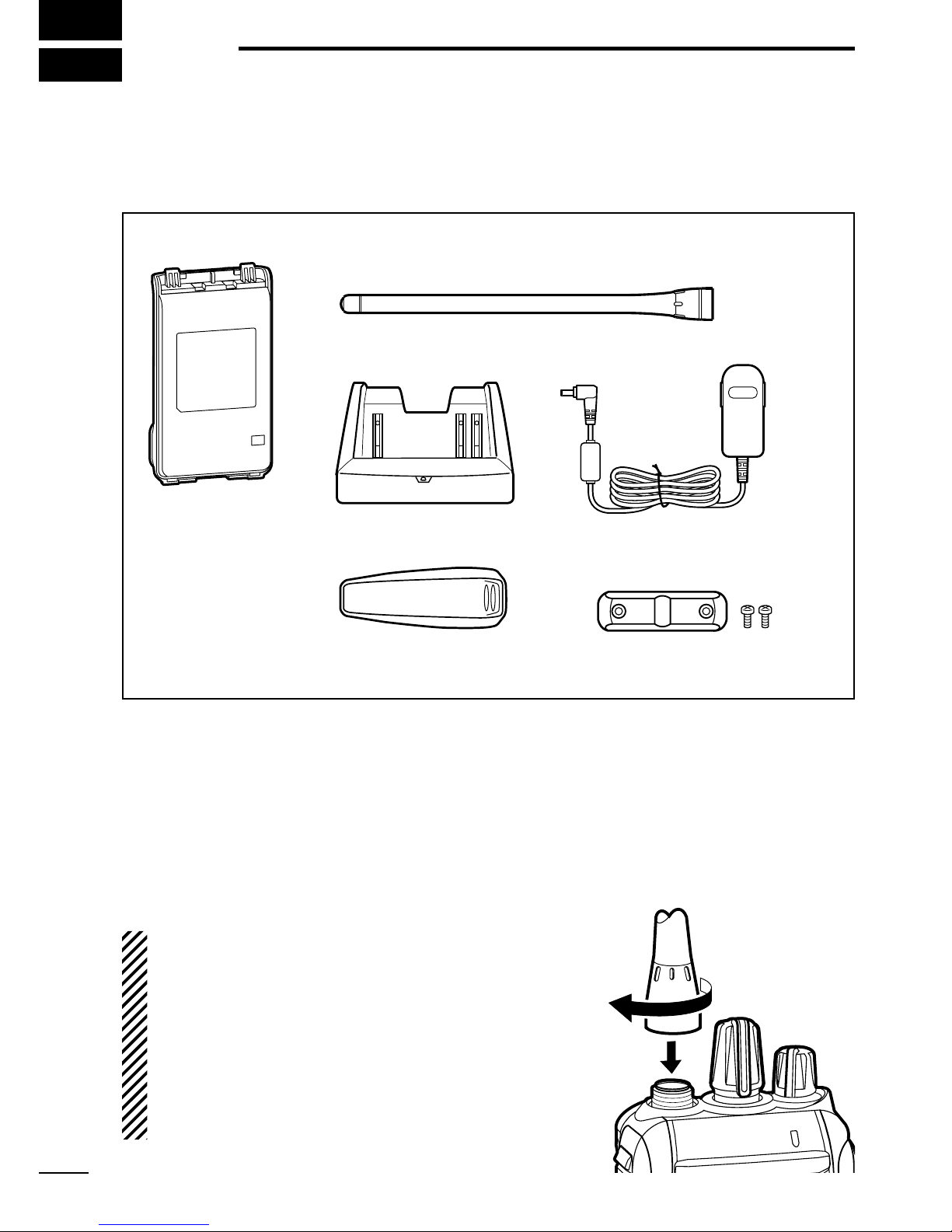
1 ACCESSORIES....................................................................1–4
N Supplied accessories............................................................1
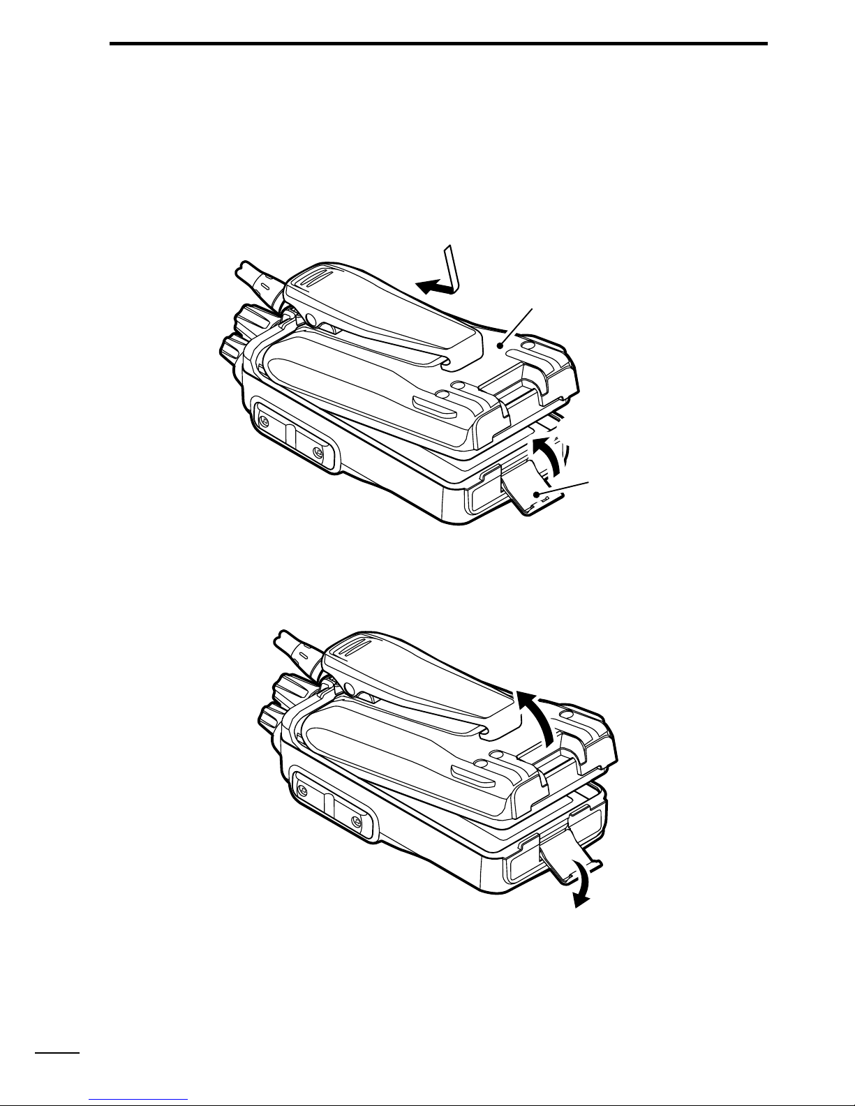
N Accessory attachments.........................................................1
2 0!.%,$%3#2)04)/. ......................................................5–11
N Front, top and side panels.....................................................5
N LED indicator ........................................................................7
N Programmable function keys.................................................8
3 "!3)#/0%2!4)/..........................................................12–22
N Turning power ON ...............................................................12
N Channel selection ...............................................................13
N Call procedure.....................................................................14
N Receiving and transmitting..................................................15
N Setting the microphone gain ...............................................18
N Setting the squelch level .....................................................19
N Output power level selection ...............................................20
N Priority A channel selection.................................................20
N MDC 1200 system operation ..............................................20
N Emergency Call...................................................................21
N Lone Worker Emergency Call .............................................22

vi
TABLE OF CONTENTS 1
2
3
4
5
6
7
8
9
10
11
12
13
14
15
16
17
18
19
20
4 BATTERY CHARGING.....................................................23–33
N Caution (for the BP-264 Ni-MH BATTERY)..............................23
N Caution (for the BP-265 Li-ion BATTERY)..............................25
N Battery chargers..................................................................28
5 BATTERY CASE ....................................................................34
N Optional battery case (BP-263)...........................................34
6 /04)/.3..........................................................................35–40
N VOX function .......................................................................38
7 SAFETY TRAINING INFORMATION ...............................41–44

NSupplied accessories
The following accessories are supplied with the transceiver.
Flexible antenna
(This illustration is for the VHF type.)
Battery pack*
Belt clip* Jack cover
(with screws)
Battery charger*AC adapter*
* Not supplied, or the shape is different, depending on the version.
NAccessory attachments
DFlexible antenna
Connect the flexible antenna to the antenna connector.
#!54)/.
sNEVER carry the transceiver by hold-
ing only the antenna.
sDO NOT connect the antenna other
than listed on page 36.
s4RANSMITTINGWITHOUTANANTENNAWILL
damage the transceiver.
1
1ACCESSORIES

2
1
ACCESSORIES
1
2
3
4
5
6
7
8
9
10
11
12
13
14
15
16
17
18
19
20
DBelt clip
To attach the belt clip:
±Slide the belt clip in the direction of the arrow until the belt clip
locks in place, and makes a ‘click’ sound.
Battery pack
Belt clip
To detach the belt clip:
qRemove the battery pack from the transceiver, if it is attached.
(p. 3)
wLift the tab up (q), and slide the belt clip in the direction of the
arrow (w).
w
q
Ta b

3
1ACCESSORIES
DBattery pack/case
To attach the battery pack/case:
qFit the battery pack/case in the direction of the arrow (q), then
close.
w Hook the latch until it makes a ‘click’ sound (w).
q
Latch
w
Battery pack/case
To remove the battery pack/case:
Unhook the latch (e), and lift up the
battery pack/case
in the
direction of the arrow (r).
e
r
Be careful! The latch is tightly locked, so use caution when re-
leasing it. DO NOT use your finger nail. Use the edge of a coin or
screwdriver tip to carefully release it.

4
1
ACCESSORIES
1
2
3
4
5
6
7
8
9
10
11
12
13
14
15
16
17
18
19
20
NEVER remove or attach the
battery pack/case
when the trans-
ceiver is wet or soiled.This may result in water or dust getting into
the transceiver,
battery pack/case,
and may result in them being
damaged.
./4% Keep the battery terminals clean. It’s a good idea to
occasionally clean them.
DJack cover
Attach the jack cover when the optional equipment is not used.
To attach the jack cover:
qAttach the jack cover to the
[SP MIC] jack.
wTighten the screws.
To detach the jack cover:
eRemove the screws with a
phillips screwdriver.
rDetach the jack cover to con-
nect the optional equipment.
r
w
w
q
e
e

5
20!.%,$%3#2)04)/.
NFront, top and side panels
Microphone
Speaker
r
w
e
q
y
u
i
tLOWER KEY
UPPER KEY
PTT SWITCH
ANTENNA
CONNECTOR
ROTARY
SELECTOR
LED INDICATOR
VOLUME
CONTROL
SPEAKER-
MICROPHONE
JACK
qROTARY SELECTOR
Rotate to select the pre-programmed memory channels.
wVOLUME CONTROL [VOL]
Rotate to turn the power ON/OFF, and adjust the audio level.

6
2
PANEL DESCRIPTION
eLED INDICATOR (p. 7)
±Lights red* while transmitting.
*When the optional battery case is attached, the LED indicator
lights orange.
±Lights green while receiving a signal, or when the squelch is
open.
±Lights/blinks orange when the matched 2/5-tone code is re-
ceived, depending on the pre-programming.
r30%!+%2-)#2/0(/.%*!#+;30-)#=
Connect the optional speaker-microphone or VOX adapter
cable.
t,/7%2+%9;,OWER=
y500%2+%9;5PPER=
The desired function can be assigned by your dealer. (p. 8)
u04437)4#(;044=
Push and hold to transmit; release to receive.
iANTENNA CONNECTOR
Connect the antenna.
1
2
3
4
5
6
7
8
9
10
11
12
13
14
15
16
17
18
19
20
Jack cover
./4% Attach the jack cover
when the optional equipment
is not used. (p. 4)

7
2PANEL DESCRIPTION
NLED indicator
The LED indicator indicates the status of various
parameters of the transceiver as follows;
(Ref.; R=Red, G=Green, O=Orange)
R* R*
TX Low BATT2 R* R* R* R*
O
O O
G G G G
G G
G G G G G G G G
R G R G R G R G R G R G R G R G
R O R O R O R O R O R O R O R O
G
G G
Clone Err
Clone TX/RX
Low BATT1
Low BATT2
Busy
F/S Scan
Call LED Blink
Call LED ON
TX Low BATT1
R*
TX
s48,IGHTS2EDWHILETRANSMITTINGASIGNAL
s28,IGHTS'REENWHILERECEIVINGASIGNAL
s#ALL,%$/.4URNS/.WHILERECEIVINGAMATCHEDTONE
s#ALL,%$"LINK"LINKSWHILERECEIVINGAMATCHEDTONE
s&AST3LOWSCAN"LINKSWHENTHE&AST3LOWSCANISACTIVATED
s,OW"ATTERY9OUSHOULDCHARGETHEBATTERYBLINKSSLOWLY
s,OW"ATTERY9OUMUSTCHARGETHEBATTERYBLINKSFAST
s48LOW"ATTERY6ERY,OW"ATTERYWASDETECTEDDURING48MODE
s#HANNEL%RROR!NONPROGRAMMEDCHANNELISSELECTED
* Lights (or blinks) orange when the optional battery case is attached.
s48LOW"ATTERY,OW"ATTERYWASDETECTEDDURING48MODE

8
2
PANEL DESCRIPTION
N0ROGRAMMABLEFUNCTIONKEYS
The following functions can be assigned to the [Upper] and [Lower]
programmable function keys.
Consult your Icom dealer or system operator for details concerning
your transceiver’s programming.
SCAN A
±Push to start and cancel the scanning operation.
±When the Power ON scan function is turned ON, push to pause
the scanning operation. The paused scan resumes after the
specified time period has passed.
SCAN B
Push to start and cancel the scanning operation.
If the scan pauses for any reason, except being cancelled by this
key, it will resume after a specified time period has passed.
PRIORITY A CHANNEL, PRIORITY B CHANNEL
Push to select the Priority A or Priority B channel.
PRIORITY A CHANNEL (REWRITE),
PRIORITY B CHANNEL (REWRITE)
±Push to select the Priority A or Priority B channel.
±Push and hold [Prio A (Rewrite)] or [Prio B (Rewrite)] for 1 sec.
to assign the operating channel to Priority A or Priority B chan-
nel, respectively.
MEMORY CHANNELS 1, 2, 3, 4
Push to directly select memory channel 1, 2, 3 or 4, if programmed.
Consult your dealer for details.
1
2
3
4
5
6
7
8
9
10
11
12
13
14
15
16
17
18
19
20

9
2PANEL DESCRIPTION
MONITOR, MONITOR (AUDIBLE)
±Push to turn the CTCSS (DTCS) or 2/5-tone squelch Mute ON
or OFF.
sOnly during LMR operation, push to open any squelch func-
tions, or deactivate any mute functions.
sOnly during PMR operation, push to activate one or two of the
following functions* on each channel.
- Push and hold to un-mute the channel (Audible mode).
- Push to mute the channel (Inaudible mode).
- Push to send a ‘reset code’ after the communication is finished.
*Ask your dealer for details.
./4% The un-mute condition may automatically return to
the mute condition, after a specified time period.
±
Depending on the presetting, pushing and holding this key for
1 sec. cancels a scan.
LOCK
Push and hold to electronically lock all programmable keys except
[Moni(Audi)], [Call] (including Call A and Call B), [Emergency],
[Surveillance] and [Lone Worker].
LONE WORKER (p. 22)
±Push to turn the Lone Worker function OFF.
±Push and hold to turn the Lone Worker function ON.
s7HENTHE,ONE7ORKERFUNCTIONISTURNED/.ANDNOOPERATIONIS
performed for the specified time period, the Emergency function is
automatically turned ON.
HIGH/LOW (p. 20)
Select the transmit output power level temporarily or permanently,
depending on the presetting.
s!SKYOURDEALERFORTHEOUTPUTPOWERLEVELFOREACHSELECTION

10
2
PANEL DESCRIPTION
TALK AROUND
±Push to turn the Talk Around function OFF.
±Push and hold to turn the Talk Around function ON.
s4HE4ALK!ROUNDFUNCTIONEQUALIZESTHETRANSMITFREQUENCYTOTHE
receive frequency for transceiver-to-transceiver communication.
WIDE/NARROW
±Push to switch the IF bandwidth to Wide.
s4HEWIDEPASSBANDWIDTHCANBESELECTEDFROMORK(ZUSING
the optional cloning software (PMR operation only). Ask your dealer
for details.
±Push and hold to switch the IF bandwidth to Narrow.
DTMF AUTODIAL
Push to transmit a programmed DTMF code.
CALL, CALL A, CALL B
Push to transmit a 2/5-tone code.
s4ONECALLTRANSMISSIONMAYBENECESSARYBEFOREYOUCALLANOTHERSTA-
tion, depending on your signalling system.
s;#ALL!=ANDOR;#ALL"=KEYSMAYBEAVAILABLEWHENYOURSYSTEMEM-
ploys selective ‘Individual/Group’ calls. Ask your dealer which call is
assigned to each key.
1
2
3
4
5
6
7
8
9
10
11
12
13
14
15
16
17
18
19
20

EMERGENCY
Push and hold for specified time period to transmit an emergency
call.
s4HEEMERGENCYCALLTRANSMITSWITHBEEPSANDTHE,%$INDICATORLIGHTS
red.
s4HETRANSCEIVERCANTRANSMITANEMERGENCYCALLWITHOUTTHEBEEP
sounding and the LED indicator lighting. Ask your dealer for details.
s)FYOUWANTTOCANCELTHEEMERGENCYCALLPUSHANDHOLDTHEKEYAGAIN
before transmitting the call.
s4HEEMERGENCYCALLISTRANSMITTEDONETIMEONLYORREPEATEDLYUNTILRE-
ceiving an acknowledgement signal, or until the power is turned OFF.
When a matched 5-tone code signal is received, the emergency func-
tion can be cancelled depending on the presetting. (PMR operation
only)
SURVEILLANCE
±Push to turn the Surveillance function OFF.
±Push and hold to turn the Surveillance function ON.
s7HENTHISFUNCTIONISTURNED/.THEBEEPISNOTHEARDANDTHE,%$
does not light when a signal is received, or a key is pushed.
SIREN
Push and hold for 1 sec. to emit a siren sound.
This function can be used for situations other than an emergency
alert, such as a security alarm for example.
The transceiver emits the siren sound until the power is turned
OFF.
11
2PANEL DESCRIPTION

12
3
"!3)#/0%2!4)/.
1
2
3
4
5
6
7
8
9
10
11
12
13
14
15
16
17
18
19
20
N4URNINGPOWER/.
Prior to using the transceiver for the first
time, the battery pack must be fully charged
for optimum life and operation. (p. 23)
±Rotate [VOL] to turn power ON.
D Battery type selection
The battery type must be selected according to the battery pack or
case when it is changed, but only the first time it is used.
Check the battery type before you begin the selection procedure.
One to three beep(s) sound in sequence, so you must repeat the
steps until the number of beeps matches your battery type.
For example, if your battery type is a Li-ion battery pack, you must
repeat the procedure until 1 beep is heard.
qSet
;2/4!29 3%,%#4/2= TO ANY
channel other than Channel 16.
wRotate [VOL] to turn the transceiv-
er power OFF.
e
While pushing and holding [PTT],
rotate [VOL] to turn the power ON.
s9OU SHOULD HOLD ;044= UNTIL THE
beeps sound. (It takes approximate-
ly 5 seconds; while holding down
[PTT], the count down beeps sound.
After that, a long beep sounds.)
s
1 beep sounds after the long beep when the Li-ion battery is selected.
s
2 beeps sound after the long beep when the battery case is selected.
s
3 beeps sound after the long beep when the Ni-MH battery is selected.
rAfter the beep sounds, release [PTT].
t Repeat steps wto runtil you select the attached battery type.
./4% This operation may not be available, depending on the
presetting. Ask your dealer for details.
[VOL]
[VOL]
[PTT]
[ROTARY SELECTOR]

NChannel selection
Several types of channel selecting methods are available. They
may differ, according to your system set up.
To select a desired operating channel, do one of the following.
s2OTATE;2/4!293%,%#4/2=
s0USHONEOFMEMORYCHANNELKEYS;-2#(=TO;-2#(=
AUTOMATIC SCAN TYPE:
Selecting a channel is not necessary for this type.When turning the
power ON, the transceiver automatically starts scanning. Scanning
stops when a call is received.
./4% If the Move to Priority A channel at Power ON function
(p. 20) is turned ON, the transceiver does not start scanning at
power ON.
13
3BASIC OPERATION
Other manuals for IC-F3000 Series
1
This manual suits for next models
1
Table of contents
Other Icom Transceiver manuals