Icom IC-M90E User manual

INSTRUCTION MANUAL
iM90E
VHF MARINE TRANSCEIVER

i
IN CASE OF EMERGENCY
If your vessel requires assistance, contact other vessels and
the Coast Guard by sending a distress call on Channel 16.
❍USING CHANNEL 16
DISTRESS CALL PROCEDURE
1. “MAYDAY MAYDAY MAYDAY.”
2. “THIS IS ...........................” (name of vessel)
3. Your call sign or other indication of the ves-
sel.
4. “LOCATED AT .....................” (your position)
5. The nature of the distress and assistance re-
quired.
6. Any other information which might facilitate
the rescue.
RECOMMENDATION
CLEAN THE TRANSCEIVER THOROUGHLY WITH FRESH
WATER after exposure to saltwater, and dry it before opera-
tion. Otherwise, the transceiver’s keys, switches and con-
trollers may become inoperable due to salt crystallization.
NOTE: DO NOT remove the battery pack when cleaning the
transceiver thoroughly with fresh water. Water may enter into
the transceiver, and damage it.
MIC
/SP

ii
FOREWORD
Thank you for purchasing this Icom radio. The IC-M90E VHF
MARINE TRANSCEIVER is designed and built with Icom’s state
of the art technology and craftsmanship. With proper care this
product should provide you with years of trouble-free operation.
IMPORTANT
READ ALL INSTRUCTIONS carefully and com-
pletely before using the transceiver.
SAVE THIS INSTRUCTION MANUAL—This in-
struction manual contains important operating instructions for
the IC-M90E.
EXPLICIT DEFINITIONS
FEATURES
☞Waterproof construction
Built tough to withstand the punishing marine environ-
ment, the IC-M90E meets IPX7 waterproof specification
while using BP-223 (option), BP-224 (option) or BP-225.
In addition to, the speaker grill adopts a new structure
which drains water or seawater easily.
☞Dualwatch and tri-watch functions
Convenient functions which allow you to monitor the dis-
tress channel (Ch 16) while receiving one other channel of
your choice (dualwatch), or while receiving one other
channel of your choice and the call channel (tri-watch).
See p. 14 for details.
☞Large, easy-to-read LCD
With dimensions of 19(H) ×35(W) mm, the IC-M90E’s func-
tion display is easy to read and shows operating conditions
at a glance. Backlighting and contrast can be adjusted to
suit your preferences.
☞Simple operation
6 large buttons on the front panel provide user-friendly op-
eration. The independent volume and channel buttons are
located on the front panel for convenient one-handed op-
eration.
WORD DEFINITION
RWARNING
CAUTION
NOTE
Personal injury, fire hazard or electric shock
may occur.
If disregarded, inconvenience only. No risk
of personal injury, fire or electric shock.
Equipment damage may occur.

iii
PRECAUTION
RWARNING! NEVER connect the transceiver to an
AC outlet. This may pose a fire hazard or result in an electric
shock.
RWARNING! NEVER hold the transceiver so that the
antenna is closer than 2.5 cm from exposed parts of the body,
especially the face or eyes, while transmitting. The trans-
ceiver will perform best if the microphone is 5 to 10 cm away
from the lips and the transceiver is vertical.
NEVER connect the transceiver to a power source other
than the BP-225, BP-224 or BP-223. Such a connection will
ruin the transceiver.
AVOID using or placing the transceiver in direct sunlight or
in areas with temperatures below –15°C or above +55°C
: MARINE, –25°C or above +55°C : PMR.
KEEP the transceiver out of the reach of children.
KEEP the transceiver at least 0.9 meters away from your
vessel’s magnetic navigation compass.
MAKE SURE the flexible antenna and battery pack are
securely attached to the transceiver, and that the antenna and
battery pack are dry before attachment. Exposing the inside
of the transceiver to water will result in serious damage to the
transceiver.
BE CAREFUL! The IC-M90E employs waterproof con-
struction, which corresponds to IPX7 waterproof specification
(1 m depth for 30 min.). However, once the transceiver has
been dropped, waterproofing cannot be guaranteed due to
the fact that the transceiver may be cracked, or the water-
proof seal damaged, etc.
Icom, Icom Inc. and the logo are registered trademarks of Icom Incor-
porated (Japan) in the United States, the United Kingdom, Germany, France,
Spain, Russia and/or other countries.

iv
IN CASE OF EMERGENCY ............................................................ i
RECOMMENDATION ....................................................................... i
FOREWORD ................................................................................... ii
IMPORTANT .................................................................................... ii
EXPLICIT DEFINITIONS ................................................................. ii
FEATURES ...................................................................................... ii
PRECAUTION ................................................................................ iii
TABLE OF CONTENTS .................................................................. iv
1 OPERATING RULES ................................................................. 1
2 SUPPLIED ACCESSORIES AND ATTACHMENTS ............... 2–3
■Supplied accessories............................................................... 2
■Attachments............................................................................. 2
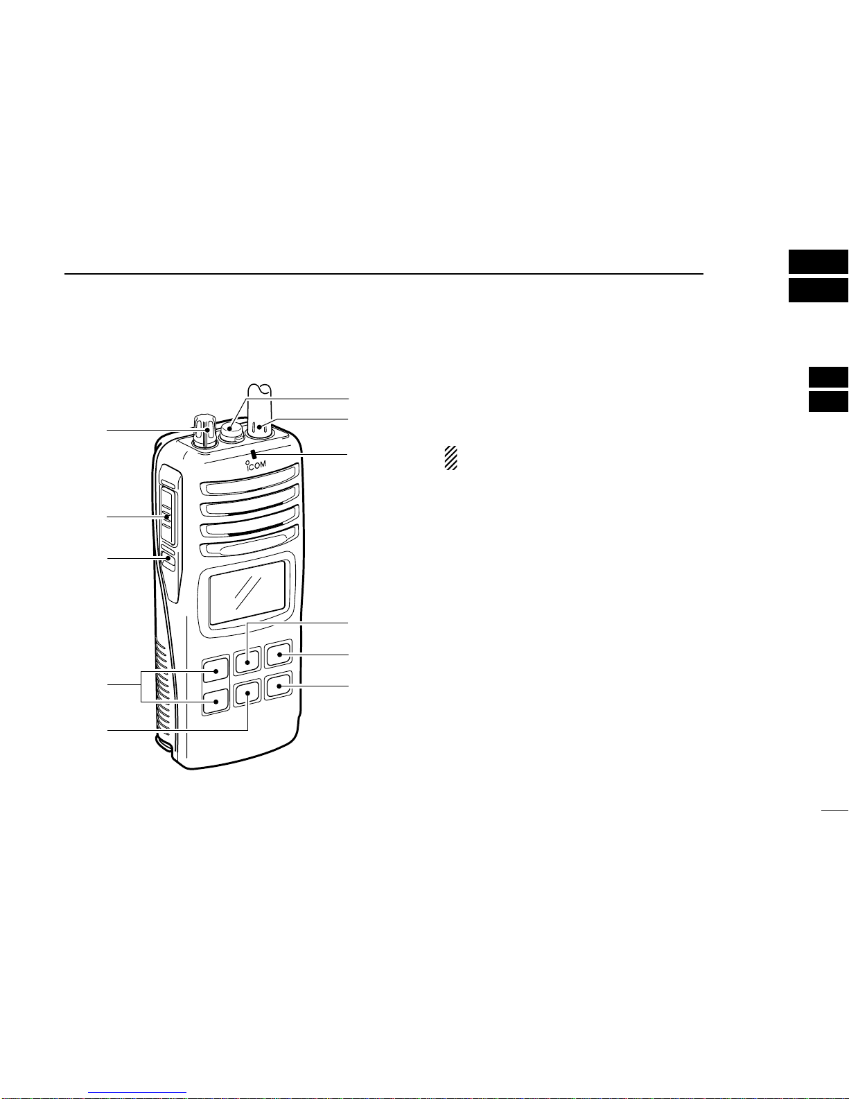
3 PANEL DESCRIPTION .......................................................... 4–6
■Front, top and side panels ....................................................... 4
■Function display ...................................................................... 5
4 BASIC OPERATION ............................................................. 7–11
■Channel selection ................................................................... 7
■Receiving and transmitting ...................................................... 9
■Call channel programming .................................................... 10
■Lock function ......................................................................... 10
■Signal strength indicator ....................................................... 10
■Monitor function .................................................................... 10
■Adjusting the squelch level .................................................... 11
■Backlighting function ............................................................. 11
■Voice scrambler operation ..................................................... 11
5 SCAN OPERATION ........................................................... 12–13
■Scan types ............................................................................ 12
■Setting tag channels ............................................................. 13
■Starting a scan ...................................................................... 13
6 DUALWATCH/TRI-WATCH ...................................................... 14
■Description ............................................................................ 14
■Operation .............................................................................. 14
7 LAND (PMR) CHANNEL OPERATION .................................... 15
■LAND (PMR) channel group ................................................. 15
■CTCSS and DTCS display .................................................... 15
■VOX function ......................................................................... 15
8 SET MODE ......................................................................... 16–21
■SET mode programming ....................................................... 16
■SET mode items ................................................................... 17
9 BATTERY CHARGING ....................................................... 22–25
■Battery charging .................................................................... 22
■Battery cautions .................................................................... 22
■Optional battery case ............................................................ 23
■Optional battery chargers ...................................................... 24
10 OPTIONAL SWIVEL BELT CLIP ............................................. 26
■MB-86 contents ..................................................................... 26
■Attachment ............................................................................ 26
■Detachment ........................................................................... 26
11 OPTIONAL SPEAKER-MICROPHONE .................................. 27
■HM-125 descriptions ............................................................. 27
■Attachment ............................................................................ 27
12 TROUBLESHOOTING ............................................................. 28
13 VHF MARINE CHANNEL LIST ............................................... 29
14 SPECIFICATIONS ................................................................... 30
15 OPTIONS ................................................................................. 31
16 QUICK REFERENCE .............................................................. 32
17 ABOUT DOC ........................................................................... 34
TABLE OF CONTENTS 1
2
3
4
5
6
7
8
9
10
11
12
13
14
15
16
17

1
OPERATING RULES
1
DPriorities
• Read all rules and regulations pertaining to priorities and
keep an up-to-date copy handy. Safety and distress calls
take priority over all others.
• You must monitor Channel 16 when you are not operating
on another channel.
• False or fraudulent distress calls are prohibited under law.
DPrivacy
• Information overheard but not intended for you cannot law-
fully be used in any way.
• Indecent or profane language is prohibited.
DRadio licenses
(1) SHIP STATION LICENSE
When your craft is equipped with a VHF FM transceiver, you
must have a current radio station license before using the
transceiver. It is unlawful to operate a ship station which is not
licensed.
Inquire through your dealer or the appropriate government
agency for a Ship-Radiotelephone license. This license in-
cludes the call sign which is your craft’s identification for radio
purposes.
(2) OPERATOR’S LICENSE
A restricted Radiotelephone Operator Permit is the license
most often held by small vessel radio operators when a radio
is not required for safety purposes.
The Restricted Radiotelephone Operator Permit must be
posted near the transceiver or be kept with the operator. Only
a licensed radio operator may operate a transceiver.
However, non-licensed individuals may talk over a transceiver
if a licensed operator starts, supervises, ends the call and
makes the necessary log entries.
A current copy of the applicable government rules and regu-
lations is only required to be on hand for vessels in which a
radio telephone is compulsory. However, even if you are not
required to have these on hand it is your responsibility to be
thoroughly acquainted with all pertinent rules and regulations.

2
2
SUPPLIED ACCESSORIES AND ATTACHMENTS
1
2
■Supplied accessories
The following accessories are supplied: Qty.
• Handstrap . . . . . . . . . . . . . . . . . . . . . . . . . . . . . . . . . . . . . 1
• Belt clip (MB-103) . . . . . . . . . . . . . . . . . . . . . . . . . . . . . . . 1
• Ni-Cd battery pack (BP-225) . . . . . . . . . . . . . . . . . . . . . . 1
• Battery charger (BC-158)* . . . . . . . . . . . . . . . . . . . . . . . . 1
• Screws for the BC-158 (M3.5 ×20)* . . . . . . . . . . . . . . . . . 2
• AC adapter (BC-147E)* . . . . . . . . . . . . . . . . . . . . . . . . . . 1
• Flexible antenna (FA-S59V) . . . . . . . . . . . . . . . . . . . . . . . 1
*Not supplied with some version.
■Attachments
DFlexible antenna
Connect the supplied flexible an-
tenna to the antenna connector.
CAUTION: Transmitting with-
out an antenna may damage
the transceiver.
NEVER HOLD by the antenna
when carrying the transceiver.
DHandstrap
Pass the handstrap through the
loop on the top of the transceiver
as illustrated at right. Facilitates
carrying.
DBelt clip
Attach the belt clip to the transceiver as illustrated below.
Supplied screws
MIC
/SP

3
2SUPPLIED ACCESSORIES AND ATTACHMENTS
ïBattery pack
To remove the battery pack:
Turn the screw counterclockwise, then pull the battery pack
in the direction of the arrow as shown below.
To attach the battery pack:
Insert the battery pack in the IC-M90E completely, then turn
the screw clockwise.
NEVER remove or insert the battery pack when the trans-
ceiver is wet or soiled. This may result water or dust get-
ting into the transceiver/battery pack and may result in the
transceiver being damaged.
NOTE: When removing or attaching the battery pack, use
a coin or flat-blade screwdriver to loosen or tighten the bot-
tom screw.
CAUTION!:
When attaching or removing a battery pack, make sure the
rubber seal is set in the groove of the battery pack cor-
rectly. If the seal is not neatly in the groove it may be dam-
aged when attaching the battery pack.
If the seal is damaged, waterproofing is not guaranteed.
OPEN
LOCK
Screw position
when removing battery
Screw position
when attaching battery
OPEN
LOCK
Make sure both the rubber seal (purple) is set to the groove
correctly and dust or else does not adhere to it.
Battery pack Battery pack
Rubber seal
Groove
Correct position Incorrect position
NOTE:
When attaching a battery pack, make sure dust or else does
not adhere to the rubber seal. If dust or else is on the seal
when attaching a battery pack, the water resistant may be
reduced.
NOTE: When the lock screw does not easily (feels tight),
check to ensure the battery pack is sufficiently inserted to
the transceiver. DO NOT bang or cause high impact to
the battery pack, as this may damage the battery pack/or
the transceiver.

4
3
PANEL DESCRIPTION
2
3
■Front, top and side panels
qVOLUME CONTROL [VOL]
Turns power ON and adjusts the audio level.
wMICROPHONE CONNECTOR [MIC/SP]
Connects the optional external microphone.
NOTE: Attach the [MIC/SP] cap when the optional
speaker-microphone is not used.
eANTENNA CONNECTOR
Connects the supplied antenna.
rTRANSMIT/RECEIVE INDICATOR
Lights green while receiving a signal or when the squelch
is open; lights red while transmitting; lights orange while
the VOX function is used.
tDIAL/CHANNEL GROUP KEY [DIAL]
•Selects one of 3 regular channels in sequence when
pushed for 1 sec. (pgs. 8, 15)
- U.S.A.*1(or ATIS*2), International and LAND (PMR)
channels are available.
*1U.K. version only.
*2German version only.
•Push to return to the condition before selecting the chan-
nel when the priority channel or the call channel is se-
lected.
ySCAN KEY [SCAN•DUAL]
•Starts and stops normal or priority scan when pushed.
(pgs. 12, 13)
•Enters watch mode when pushed for 1 sec. (p. 14)
MIC
/SP
qe
r
y
t
w
i
u
o
!1
!0

5
3PANEL DESCRIPTION
uTRANSMIT POWER/LOCK KEY [Hi/Lo•]
•Selects high, middle or low power when pushed. (p. 9)
•Toggles the lock function ON/OFF when pushed for
1 sec. (p. 10)
iCHANNEL 16 KEY [16•C]
•Selects Channel 16 when pushed. (p. 7)
•Selects call channel when pushed for 1 sec. (p. 7)
•Enters call channel write mode when the call channel is
selected and this key is pushed for 3 sec. (p. 10)
oCHANNEL UP/DOWN SWITCHES [YY]/[ZZ]
•Selects an operating channel. (pgs. 7–9)
•Selects the SET mode condition of the item. (p. 16)
•Selects the SET mode item when pushed with
[SQL•MONI]. (p. 16)
•Checks tag channels or changes scanning direction dur-
ing scan. (p. 13)
!0 SQUELCH SWITCH [SQL•MONI]
•Push this switch, then adjust the squelch level with
[YY]/[ZZ]. (p. 11)
•Manually opens the squelch for monitoring the channel
while pushed and held. (p. 10)
•While pushing this switch, turn power ON to enter the
SET mode. (p. 16)
•Selects the SET mode item. (p. 16)
!1 PTT SWITCH [PTT]
Push and hold to transmit; release to receive.
■Function display
qSIGNAL STRENGTH INDICATOR (pgs. 10, 20)
Shows the relative signal strength while receiving signals.
wTRANSMIT POWER INDICATOR
•“LOW”appears when low power is selected.
•“MID”appears when middle power is selected.
•No indication appears when high power is selected.
eTAG CHANNEL INDICATOR (p. 13)
Appears when tag channel is selected.
rSQUELCH LEVEL INDICATOR (p. 11)
Shows the squelch level.
q r t yw e
u
i
o
!0
!1
!2
!4
!6
!5
!3

6
3
PANEL DESCRIPTION
3
tMONITOR INDICATOR (p. 10)
Appears when the monitor function is activated.
yBATTERY INDICATOR
Indicates remaining battery power.
uSCAN INDICATOR (p. 13)
“SCAN”blinks during scan.
iVOX INDICATOR (p. 15)
“VOX”appears when the VOX function is used.
oDUALWATCH/TRI-WATCH INDICATORS (p. 14)
“DUAL”blinks during dualwatch; “TRI”blinks during tri-
watch.
!0 SCRAMBLER INDICATOR
Appears when the optional voice scrambler is activated.
(pgs. 11, 20)
!1 DUPLEX INDICATOR
Appears when a duplex channel is selected.
!2 SUB CHANNEL READOUT
•Indicates Channel 16 during priority scan or dualwatch.
(p. 14)
•Indicates the SET mode items while in the SET mode.
(p. 16)
!3 CHANNEL NUMBER READOUT
•Indicates the selected operating channel number.
•In SET mode, indicates the selected condition.
!4 LOCK INDICATOR
Appears when the lock function is activated.
!5 CALL CHANNEL INDICATOR
Appears when the call channel is selected.
!6 CHANNEL GROUP INDICATOR
“I”appears when International; “U”appears when U.S.A.
(U.K. version only); “”appears when LAND (PMR)
channel group is selected. “ATIS”appears when the chan-
nel group in whichATIS function is activated (German ver-
sion only).
Indication
Full Middle Charging
required No battery
Battery level
blinks when the battery is exhaustion.
blinks when the battery is over charged.

7
BASIC OPERATION
4
■Channel selection
IMPORTANT!: Prior to using the transceiver for the first
time, the battery pack must be fully charged for optimum
life and operation. To avoid damage to the battery pack or
charger, turn the power OFF while charging.
DChannel 16
Channel 16 (Distress channel) is used for establishing initial
contact with another station and for emergency communica-
tions. Channel 16 is automatically monitored during both
dualwatch and tri-watch. While standing by, you must monitor
Channel 16.
qPush [16•C] to select Channel 16.
wPush [DIAL] to return to the condition before selecting
Channel 16, or push [Y]/[Z] to select the operating
channel.
DCall channel
Each regular channel group has separate call channels. In
addition, the call channel is monitored during tri-watch. The
call channels can be re-programmed (p. 10) and may be used
to store your most often used channel in each channel group
for quick recall.
qPush [16•C] for 1 sec. to select the call channel.
•“CALL”and the call channel number appear.
•Call channel can be re-programmed. See the “Call channel
programming”on p. 10 for details.
wPush [DIAL] to return to the condition before selecting the
call channel, or push [Y]/[Z] to select the operating chan-
nel.
Push
NOTE: Channel 16 is default setting.
(Depending on version)
for 1 sec.
Push

8
4
BASIC OPERATION
4
D
International, U.S.A.*
1
and ATIS*
2
channels
The IC-M90E has 57*3International, 59 U.S.A.*1and 57
ATIS*2channels. You must select the proper channels for the
operating area.
*3International channel numbers are depended on versions.
qPush [DIAL] to select the regular channel.
wPush [Y]/[Z] to select a channel.
•“DUP”appears for duplex channels.
eTo change the channel group, push [DIAL] for 1 sec.
•International, U.S.A*1and ATIS*2channels can be selected in
sequence. Depending on the setting, LAND (PMR) channel can
be selected. See the “LAND (PMR) CHANNEL OPERATION”on
p. 15 for details.
*1U.K. version only.
*2German version only.
Push for 1 sec.
International
channels
U.S.A. channels*1ATIS channels*2
Push for 1 sec.

9
4BASIC OPERATION
■Receiving and transmitting
qRotate [VOL] clockwise to turn power ON.
wSet the volume and squelch level.
➥Push [SQL•MONI], and push [√] to open the squelch.
➥Push [SQL•MONI] to stop “SQL”indicator blinking, then
rotate [VOL] to set the volume level.
➥Push [SQL•MONI], and push [∫]/[√] to set the squelch
level.
ePush [Y]/[Z] to select the desired channel.
- When receiving a signal, the [TRANSMIT/RECEIVE] indicator
lights green while audio is emitted from the speaker.
- Further adjustment of [VOL] may be necessary at this point.
rPush [Hi/Lo•] to select the output power if necessary.
- “LOW”appears when low power is selected; “MID”appears
when middle power is selected; no indication when high power is
selected.
- Choose low power to conserve battery power, choose high
power for longer distance communications.
tPush and hold [PTT] to transmit, then speak into the
microphone.
- The [TRANSMIT/RECEIVE] indicator lights red while
transmitting.
- Channel 70 cannot be used for transmission.
yRelease [PTT] to receive.
IMPORTANT: To maximize the readability of your trans-
mitted signal, pause a few sec. after pushing [PTT], hold
the microphone 5 to 10 cm from your mouth and speak
into the microphone at a normal voice level.
NOTE: The transceiver has a power save function to con-
serve the battery power. The power save function activates
automatically when no signal is received for 5 sec.
To prevent accidental prolonged transmission, etc., the IC-
M90E has a time-out-timer function. This timer cuts a
transmission OFF after 5 min. of continuous transmission.
CAUTION: Transmitting without an antenna may
damage the transceiver.
MIC
/SP
q Power ON
w Set volume
Speaker
t Push to transmit
y Release to receive
w Set the squelch level
e Set channel
w Set the squelch level
Microphone
r Set output power

10
4
BASIC OPERATION
4
■Call channel programming
The call channel key is used to select the default channel,
however, you can program your most often-used channel in
each channel group for quick recall.
qPush [DIAL] for 1 sec. several times
to select the desired channel group
(INT, USA*1, ATIS*2) to be pro-
grammed.
*
1
U.K version only, *
2
German version only
wPush [16•C] for 1 sec. to select the
call channel.
•“CALL”and the call channel number
appear.
ePush [16•C] again for 3 sec. (until a
long beep changes to 2 short beeps)
to enter call channel programming
condition.
•Call channel number to be programmed
flashes.
rPush [Y]/[Z] to select the desired
channel.
tPush [16•C] to program the dis-
played channel as the call channel.
•The call channel number stop
flashing.
■Lock function
This function electronically locks all keys (except for [PTT],
[SQL•MONI] and [Hi/Lo•]) to prevent accidental channel
changes and function access.
➥Push [Hi/Lo•] for 1 sec. to turn the lock function ON
and OFF.
■Signal strength indicator
The received signal strength level is indicated by number of
bars as below.
This indicator can be hidden by using the SET mode (p. 20) if
desired.
■Monitor function
The monitor function releases the noise squelch mute manu-
ally. This function is convenient when receiving a weak sig-
nal, or when adjusting the volume level, etc.
➥Push [SQL•MONI] for 1 sec. and keep holding to activate
the monitor function.
•“ ”appears and audio is emitted.
Indication
Strong Middle Weak No signal or
very weak
Signal
strength
Appears while the lock
function is used.

11
4BASIC OPERATION
■Adjusting the squelch level
To adjust the IC-M90E’s squelch level, use the [Y]/[Z] keys as
described below. In order to receive signals properly, as well
as for the scan to function effectively, the squelch must be ad-
justed to the proper level.
qPush [SQL•MONI], then adjust the squelch level with [Y]/[Z].
- “SQL”indicator starts blinking.
- There are 11 squelch levels to choose from: OP is completely
open; 10 is tight squelch; 1 is loose squelch level.
wPush [SQL•MONI] again to return to normal condition.
- When no switch is pushed for 5 sec., the transceiver returns to
normal condition.
■Backlighting function
This function is convenient for nighttime operation. The back-
lighting brightness can be adjusted in the SET mode. (p. 18)
➥Push any key except [PTT] to turn the backlighting ON.
•The backlighting is automatically turned OFF after 5 sec. of
inactivity.
■Voice scrambler operation
DActivating the scrambler
The voice scrambler provides private communications. In
order to receive or send scrambled transmissions, you must
activate the scrambler function first.
q
Select an operating
channel except Channel
16 or 70.
wWhile pushing and
holding [SQL•MONI],
push [SCAN•DUAL].
•“SCRM”appears.
eTo turn the scrambler
function OFF, repeat
step w.
•“SCRM”disappears.
DProgramming scramble codes
32 scrambler codes (1 to 32) are available for voice scrambler
operation. Set the code in the SET mode. In order to under-
stand each other, all transceivers in your group must have the
same scrambler code. See p.
20
for “Scrambler code”setting
details.
Appears when the voice
scrambler function is in use.
Blinks during the squelch
level adjutment.
Indicates the
squelch level.
Push

12
5
SCAN OPERATION
4
5
■Scan types
Scanning is an efficient way to quickly locate signals over a
wide frequency range. The transceiver has a priority scan set-
ting and normal scan setting.
In addition, the “Auto scan”function is available for scanning.
This function can be activated simultaneously, depending on
the settings on the SET mode. (p. 17)
Set the tag channels (scanned channel) before scanning.
Clear those tag channels which are not needed or inconve-
niently stop scanning, such as digital communications.
Choose priority or normal scan on the SET mode. (p. 17)
PRIORITY SCAN
Priority scan searches through all tag channels in sequence
while monitoring Channel 16. When a signal is detected on
Channel 16, scan pauses until the signal disappears; when
a signal is detected on a channel other than Channel 16,
scan becomes dualwatch until the signal disappears.
CH88
CH 01
CH 16
CH 02
CH 05 CH 04
CH 03
NORMAL SCAN
Normal scan, like priority scan, searches through all tag
channels in sequence. However, unlike priority scan, Chan-
nel 16 is not checked unless Channel 16 is set as a tag
channel.
CH 01 CH 02
CH88
CH 05 CH 04
CH 03

13
5SCAN OPERATION
■Setting tag channels
For more efficient scanning, add desired channels as tag
channels or clear the tag for unwanted channels.
Non-tag channels will be skipped during scanning. Tag chan-
nels can be assigned to each channel group (INT, USA*1,
ATIS*2) independently.
qSelect the desired channel group (INT, USA*1, ATIS*2) by
pushing [DIAL] for 1 sec., if desired.
*1U.K. version only, *2German version only
wSelect the desired channel to set as a tag channel.
ePush both [Y] and [Z] for 1 sec. to set the displayed chan-
nel as a tag channel.
•“ ”appears in the function display.
rTo cancel the tag channel setting, push both [Y] and [Z]
for 1 sec.
•“ ”disappears.
✔Clearing all tag channels in the selected channel group
While pushing and holding both [Y] and [Z], turn power ON
to clear all tag channels in the channel group.
■Starting a scan
Set the priority scan function, scan resume timer and auto
scan function in advance, using the SET mode. (p. 17)
qSelect the desired channel group (INT, USA*1, ATIS*2) by
pushing [DIAL] for 1 sec., if desired.
*1U.K. version only, *2German version only
wPush [SCAN•DUAL] to start priority or normal scan.
•“SCAN”blinks in the function display.
•“16”appears on the sub channel readout during priority scan.
•When a signal is received, scan pauses until the signal disap-
pears or resumes after pausing 5 sec. according to scan resume
timer setting. (Channel 16 is still monitored during priority scan.)
•Push [Y]/[Z] to check the scanning tag channels, change the
scanning direction or resume the scan manually.
eTo stop the scan, push [SCAN•DUAL].
•“SCAN”disappears.
•Pushing [PTT], [16•C] or [DIAL] also stops the scan.
[Example]: Starting a normal scan.
Scan starts.
Push
to stop the scan
Receiving a signal
and audio is emitted. Push

14
6
DUALWATCH/TRI-WATCH
5
6
■Description
Dualwatch monitors Channel 16 while you are receiving
another channel; tri-watch monitors Channel 16 and the call
channel while receiving another channel.
■Operation
qSelect the desired operating channel.
wPush [SCAN•DUAL] for 1 sec. to start dualwatch or tri-watch
(depending on the SET mode setting).
•“DUAL”blinks during dualwatch; “TRI”blinks during tri-watch.
•A beep tone sounds when a signal is received on Channel 16.
•Tri-watch becomes dualwatch when receiving a signal on the call
channel.
eTo cancel dualwatch/tri-watch, push [SCAN•DUAL] again.
DUALWATCH/TRI-WATCH SIMULATION
•If a signal is received on Channel 16, dualwatch/tri-watch
pauses on Channel 16 until the signal disappears.
•If a signal is received on the call channel during tri-watch,
tri-watch becomes dualwatch until the signal disappears.
•To transmit on the selected channel during dualwatch/tri-
watch, push and hold [PTT].
Dualwatch Tri-watch
Call channel
[Example]: Operating tri-watch on INT channel 07.
Push
for 1 sec. Signal is received
on the call channel.
Signal is received
on Channel 16
takes priority.
Tri-watch resumes
after the signal
disappears.
Tri-watch starts.

15
LAND (PMR) CHANNEL OPERATION
7
■LAND (PMR) channel group
A max. of 100 PMR channels (allocated 146.000 to 174.000
MHz) can be programmed into the LAND channel group for
simple communication with PMR transceivers in the VHF
band.
Moreover, any of the marine channels in the USA*1, INT and
ATIS*2channel groups can be programmed.
The default setting of the LAND channel group is the same
as that of the INT channel group. Ask your local Icom dealer
for the LAND channel group setting and PMR frequency pro-
gramming details.
*1U.K. version only, *2German version only
qPush [DIAL] to select a regular channel.
wTo change the channel group, push [DIAL] for 1 sec. sev-
eral times.
•“ ”appears when LAND channel group is selected.
ePush [Y]/[Z] to select a channel.
•“DUP”appears for duplex channels.
NOTE: The default settings (e.g. call channel program-
ming) of the LAND channel group are same as the Interna-
tional and U.S.A. channels. Refer to the appropriate pages
for details.
■CTCSS and DTCS display
When DTCS or CTCSS is set in the selected channel, the
sub channel readout displays as below.
■VOX function
The VOX function (voice operated transmission) starts trans-
mission without pushing [PTT] when you speak into the mi-
crophone; then automatically returns to receive when you
stop speaking (hands-free operation becomes possible).
NOTE: An optional headset and headset adapter is re-
quired for the VOX operation.
➥Push and hold [SQL•MONI], then push [Hi/Lo•] to turn
the VOX function ON/OFF while connecting the optional
headset and headset adapter to [MIC/SP] connector.
•“VOX”appears on the LCD while the VOX function turns ON.
•The “VOX gain”and “VOX delay”can be set in the SET mode.
(p. 21)
Push for 1 sec.
several times.
Appears when DTCS is set.
Appears when CTCSS is set.
Other manuals for IC-M90E
1
Table of contents
Other Icom Transceiver manuals