Icom IC-F9010 SERIES User manual

OPERATING GUIDE
FOR IC-F9010/IC-F9020/
IC-F9510/IC-F9520 SERIES
ANALOG/MDC 1200 SYSTEM
/
APCO P25 MODE OPERATIONS

i
Thank you for purchasing this Icom transceiver.
The Analog/MDC 1200 system/APCO P25 system functions
are usable for your transceiver.
READ ALL INSTRUCTIONS OF THE SYSTEM
carefully and completely before using the transceiver.
SAVE THIS OPERATING GUIDE — This operating
guide contains important operating instructions for,
• IC-F9011B/S/T v h f p25 t r u n k i n g h a n d h e l d t r a n s c e i v e r s
• IC-F9021B/S/T, IC-F9023B/S/T u h f p25 t r u n k i n g h a n d h e l d
t r a n s c e i v e r s
• IC-F9511S/T/HT v h f p25 t r u n k i n g m o b i l e t r a n s c e i v e r s
• IC-F9521S/T, IC-F9523S/T u h f p25 t r u n k i n g m o b i l e t r a n s -
c e i v e r s
✔ INFORMATION:
In this operating guide, the following descriptions are used;
• “Non-display types” : Models ending in “B”
• “Simple types” : Models ending in “S”
• “10-key types” : Models ending in “T” (including “HT”)
Icom, Icom Inc. and the Icom logo are registered trademarks of Icom Incor-
porated (Japan) in Japan, the United States, the United Kingdom, Germany,
France, Spain, Russia and/or other countries.
All other products or brands are registered trademarks or trademarks of their
respective holders.
IMPORTANT

ii
IMPORTANT.......................................................................... i
TABLE OF CONTENTS........................................................ ii
1 PREPARATION..........................................................1–10
n Programmable key functions ........................................1
2 ANALOG MODE OPERATION................................11–14
n Tone Signaling............................................................11
n TX Code CH Selection ...............................................11
n DTMF transmission ....................................................12
n Scrambler function .....................................................12
n Emergency transmission............................................13
n Man Down Emergency Call
(Handheld transceivers only) .....................................14
3 MDC 1200 SYSTEM OPERATION ..........................15–24
n MDC 1200 system operation......................................15
n Receiving a call ..........................................................15
n Transmitting a call.......................................................19
nMan Down Emergency Call
(Handheld transceivers only) .....................................24
n Status message transmission ....................................24
4 APCO P25 MODE OPERATION .............................25–57
n General.......................................................................25
n Control Channel Hunt function
(P25 Trunking mode only) ..........................................26
n Roaming function (P25 Trunking mode only) .............28
n Site Lock function (P25 Trunking mode only) .............28
n Site Select function (P25 Trunking mode only)...........29
n Individual call..............................................................29
n Talkgroup call..............................................................31
n Pager function ............................................................33
n Radio Inhibit function..................................................35
n Radio Uninhibit function .............................................37
n Remote Monitor function ............................................39
n Radio Check function .................................................41
n Status Message .........................................................43
n Short Message...........................................................45
n Status Query function.................................................47
n Phone call ..................................................................49
n Announcement function ............................................51
nEmergency transmission............................................52
n Man Down Emergency Call
(Handheld transceivers only) .....................................54
n Talk Back function.......................................................55
n Encryption function.....................................................56
5 TACTICAL GROUP FUNCTION..............................58–62
n Tactical Group function...............................................58
TABLE OF CONTENTS 1
2
3
4
5
6
7
8
9
10
11
12
13
14
15
16

nProgrammable key functions
The programmable key functions can be assigned to the fol-
lowing keys and switches;
Handheld transceivers:
[EMR], [Side1], [Side2], [Side3], [I]*1, [II]*1, [III]*1, [Ω]*1, [≈]*1,
[∫]*1, [√]*1, [APP]*1, [HOME]*1, ABC switch and Toggle
switch.
*1 Available on Simple and 10-key types only
Mobile transceivers:
[UP]*2, [DOWN]*2, [P0], [P1], [P2], [P3] and [P4].
*2Available on 10-key types only
Consult your Icom dealer or system operator for details con-
cerning your transceiver’s programming.
For Handheld transceivers:
❍ABC and Toggle switches
The programmable key functions for the ABC and Toggle
switches are limited. (See p. 10 for details.)
❍Key indicator (Simple and 10-key types only)
If the key indicator shows the programmed function key
name, push the front panel key ([I], [II] or [III]) under the key
indicator to activate the programmed function.
( In the explanations that follow, the function key name for that
key indicator is displayed in double quotation marks; e.g.
“EMR.”)
❍Non-display types
The programmable key functions are limited, and some key
functions operate differently between the Simple and 10-key
types.
1
1PREPARATION

2
1
PREPARATION
1
2
3
4
5
6
7
8
9
10
11
12
13
14
15
16
DProgrammable key functions availability
Programmable
key functions
Analog APCO P25 REF.
HH MB HH MB
CH Up, CH Down ✔*2✔ ✔*2✔IM
CH Up/Down N/A ✔N/A ✔IM
Zone ✔*2✔ ✔*2✔IM
Zone Up/Down N/A ✔N/A ✔IM
Scan A, Scan B ✔*1✔ ✔*1✔IM
Scan Add/Del(Tag) ✔*2✔ ✔*2✔IM
Prio A, Prio B ✔✔✔✔ IM
Prio A (Rewrite),
Prio B (Rewrite) ✔*1✔ ✔*1✔IM
MR-CH 1, 2, 3, 4 ✔✔✔✔ IM
Moni ✔✔✔✔ IM
Public Address N/A ✔N/A ✔IM
RX Speaker N/A ✔N/A ✔IM
Light ✔✔✔✔ IM
Lock ✔✔✔✔ IM
Talk Around ✔*1✔ ✔*1✔IM
Programmable
key functions
Analog APCO P25 REF.
HH MB HH MB
High/Low ✔*1✔ ✔*1✔IM
Surveillance*3✔✔✔✔ IM
Hook Scan N/A ✔N/A ✔IM
OPT1 Out, OPT2 Out,
OPT3 Out ✔*1✔ ✔*1✔IM
OPT1 Momentary,
OPT2 Momentary,
OPT3 Momentary
✔✔✔✔ IM
User Set Mode ✔*2✔ ✔*2✔IM
Clock ✔*2✔ ✔*2✔IM
Menu <, Menu > ✔*2N/A ✔*2N/A IM
Re-dial ✔ ✔ N/A N/A p. 4
DTMF Autodial ✔*1✔N/A N/A p. 4
Compander ✔*1✔N/A N/A pp. 4, 10
Scrambler ✔*1✔N/A N/A pp. 4, 10
Emergency ✔✔✔✔ p. 5
Lone Worker*3✔✔✔✔ p. 5
☞ Continued on the next page
HH: Handheld MB: Mobile
IM: Instruction Manual N/A: Not Applicable
*1 Simple/10-key and Non-display types operate differently.
*2Not available on Non-display types.
*3 With revision 1.7 or later transceivers, Simple/10-key and Non-
display types operate differently.

3
1PREPARATION
Programmable
key functions
Analog APCO P25 REF.
HH MB HH MB
Home ✔✔✔✔pp. 5, 6
Ext.CH Sel Mode N/A ✔N/A ✔p. 6
Scrambler/Encryption ✔*1✔ ✔*1✔pp. 6, 10
Zeroize N/A N/A ✔ ✔ p. 7
Site Lock N/A N/A ✔ ✔ pp. 7, 10
Encryption N/A N/A ✔*1✔pp. 7, 10
Digital Button N/A N/A ✔*2✔p. 8
Digital Status N/A N/A ✔*2✔p. 8
Dgital Page N/A N/A ✔*2✔p. 8
Digital Message N/A N/A ✔*2✔p. 8
Phone N/A N/A ✔*2✔p. 8
Site Select N/A N/A ✔*2✔p. 9
Individual N/A N/A ✔*2✔p. 9
Talkgroup N/A N/A ✔*2✔p. 9
Rekey N/A N/A ✔*2✔p. 9
Keyset N/A N/A ✔*2✔p. 9
D Programmable functions availability (Continued)
Programmable
key functions
Analog APCO P25 REF.
HH MB HH MB
Scan ✔*1✔ ✔*1✔IM
C.Tone CH Ent ✔*2✔N/A N/A p. 4
Call, Call A, Call B ✔ ✔ N/A N/A p. 4
TX Code CH Select ✔*2✔N/A N/A p. 4
TX Code CH UP,
TX Code CH DN ✔*2✔N/A N/A p. 4
MDC Call ✔*2✔N/A N/A p. 5
MDC SelCall ✔*2✔N/A N/A p. 5
MDC CallAlert ✔*2✔N/A N/A p. 5
Tone/NAC CH Select ✔*2✔ ✔*2✔p. 7
[Scan] is programmable instead of [Scan A] and [Scan B].
HH: Handheld MB: Mobile
IM: Instruction Manual N/A: Not Applicable
*1Simple/10-key and Non-display types operate differently.
*2Not available on Non-display types.
With revision 1.7 or later transceivers, the following keys are addi-
tionally programmable.

4
1
PREPARATION
1
2
3
4
5
6
7
8
9
10
11
12
13
14
15
16
DAnalog mode operation
(Common operation)
RE-DIAL KEY “DTMR”
Push to transmit the last-transmitted DTMF code.
(Simple/10-key and Non-display types operate differently)
DTMF AUTODIAL KEY “DTMA” (p. 12)
❍For Simple and 10-key types
➥Push to enter the DTMF channel selection mode, then
select a desired channel using [CH Up]/[CH Down] or [CH
Up/Down].
➥After selecting the channel, push to transmit the DTMF
code.
❍For Non-display types
➥Push to transmit the DTMF code programmed in DTMF
channel 1.
COMPANDER KEY “COMP”
❍For Simple and 10-key types
Push to turn the Compander function ON or OFF.
This function reduces noise components from the transmit-
ted audio to provide clear communication.
❍For Non-display types
➥
Push and hold for 1 sec. to turn the Compander function ON.
➥If the function is ON, push to turn it OFF.
SCRAMBLER KEY “SCR” (p. 12)
❍For Simple and 10-key types
Push to turn the Voice Scrambler function ON or OFF.
❍For Non-display types
➥ Push and hold for 1 sec. to turn the Voice Scrambler func-
tion ON.
➥If the function is ON, push to turn it OFF.
The following functions are programmable for only trans-
ceivers whose revision number is 1.7 or later.
(Not available on Non-display types)
CALL KEYS “CALL” “CALA” “CALB” (p. 11)
Push to transmit a 2-tone code.
• Call transmission is necessary before you call another station, de-
pending on your signaling system.
• [Call A] and/or [Call B] may be available when your system em-
ploys selective ‘Individual/Group’ calls. Ask your dealer which call is
assigned to each key.
TX CODE CHANNEL SELECT KEY “TXC” (p. 11)
Push to enter the ID code channel selection mode, and then
select a desired channel using
[CH Up]/[CH Down] or [CH
Up/Down].
TX CODE CHANNEL UP/DOWN KEYS “TXCU” “TXCD” (p. 11)
Push to select a TX code channel directly.
C.TONE CH ENT KEY “T SEL”
Push to enter the continuous tone channel selection mode,
and then select a desired tone frequency/code setting using
[CH Up]/[CH Down] or [CH Up/Down]. The selected chan-
nel remains set as the continuous tone channel until another
channel is designated as such.

5
1PREPARATION
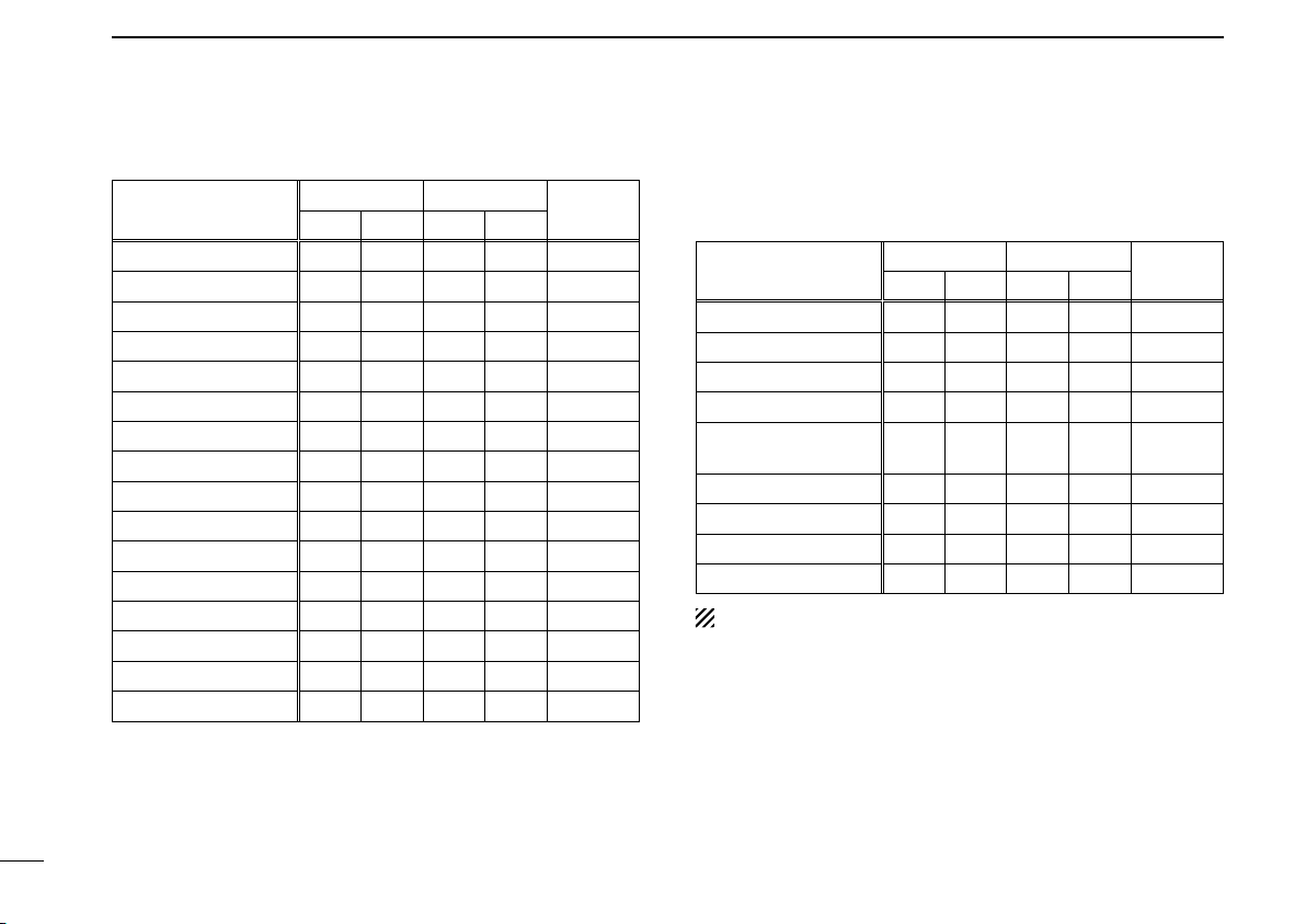
DMDC 1200 system operation
The following functions are programmable for only trans-
ceivers whose revision number is 1.7 or later.
(Not available on Non-display types)
MDC CALL KEY “MDC”
➥Push to enter the MDC menu selection mode, then select
a desired MDC menu from “SELCALL,” “CALALERT,”
“STUN,” “REVIVE,” “RADIOCHK,” “STATUS,” “MSG,” “STAT
POL,” and “CALL LOG” using [CH Up]/[CH Down] or [CH
Up/Down].
After selecting, push this key again to enter the transceiv-
er alias selection mode.
• If no operation is performed for about 15 sec., the transceiver
returns to the normal operating mode.
➥While in the transceiver alias selection mode, push to
return to the MDC menu selection mode.
MDC SELCALL KEY “SELC” (p. 19)
Push to enter the transceiver alias selection mode for SelCall.
• After the desired alias selection, push [PTT] to transmit a SelCall.
• If no operation is performed for about 15 sec., the transceiver
returns to the normal operating mode.
MDC CALLALERT KEY “CALA” (p. 19)
Push to enter the transceiver alias selection mode for
CallAlert.
• After the desired alias selection, push [PTT] to transmit a CallAlert.
• If no operation is performed for about 15
sec.
, the transceiver
returns to the
normal operating mode.
DAnalog and APCO P25 modes operation
(Common operation)
EMERGENCY KEY “EMR” (pp. 13, 23, 52)
Push and hold for the specified time period*, to enter the
emergency mode. After the specified time period* has passed,
an Emergency call or alarm is transmitted once, or repeat-
edly*.
• To exit the emergency mode, push and hold for the specied time pe-
riod* again before transmitting.
* Depending on the pre-setting. Ask your dealer for details.
LONE WORKER KEY “LONE”
Push to turn the Lone Worker function ON or OFF.
• If the Lone Worker function is activated, the Emergency function is
automatically turned ON after the specied time period* has passed
with no operation performed.
* Depending on the pre-setting. Ask your dealer for details.
With Non-display types whose revision number is 1.7 or
later, push and hold this key for 1 sec. to turn the Lone
Worker function ON. If the function is ON, push to turn it
OFF.
HOME KEY “HOME”
➥Push to return to the normal operating mode from each
selected mode, such as Individual ID, Talkgroup ID, DTMF
code channel, and so on.
➥ When the Full Off Air Call SetUp (FOACSU) function is
turned ON on the Trunking mode, push to ignore the re-
ceiving call. (p. 30)

[Home] has the following additional functions with trans-
ceivers whose revision number is 1.7 or later
:
➥ While in the emergency mode, push to exit the mode.
➥
While in the APCO P25 mode, push to cancel the talk
back function.
Ext. CH Sel Mode KEY (Available on Mobile transceivers only)
Push to turn the Memory Channel Select function from an ex-
ternal input ON or OFF.
When this function is turned ON, and a signal is input from an
external unit that is connected to the D-sub 25-pin connector,
the operating channel changes to the desired memory chan-
nel. In that case, a memory channel selection with the key or
dial operation, and the microphone hanger action functions,
Move to Priority A Channel and On Hook Scan, are disabled.
When this function is turned OFF, the memory channel selec-
tion from an external input is disabled.
• This function is usable when an external unit is connected to the
transceiver.
• Ask your dealer for details of an external input.
(Simple/10-key and Non-display types operate differently)
SCRAMBLER/ENCRYPTION KEY “S/D”
- The UT-125 aes/des encryption unit or UT-128 des encryption
u n i t is required for the Encryption function.
❍For Simple and 10-key types
➥ While in the analog mode, push to turn the Voice Scrambler
function ON or OFF.
➥While in the APCO P25 mode, push to turn the Encryption
function ON or OFF.
➥ While in the mixed (digital and analog) mode, push to turn
the Voice Scrambler and Encryption functions ON or OFF,
separately or simultaneously, as shown below.
Voice Scrambler function ON (“SCRM” appears* / “ ” appears)
Voice Scrambler and Encryption functions ON
(“SCRM/ENC” appears* / “ ” appears)
Voice Scrambler and Encryption functions OFF
(“OFF” appears* / “ ” disappears)
Encryption function ON (“ENC” appears* / “ ” appears)
PUSH
PUSH
PUSH
PUSH
* Appears for about 1 sec.
❍For Non-display types
➥While in the analog mode, push and hold for 1 sec. to turn
the Voice Scrambler function ON. If the function is ON,
push to turn it OFF.
➥While in the APCO P25 mode, push and hold for 1 sec.
to turn the Encryption function ON. If the function is ON,
push to turn it OFF.
➥
While in the mixed (digital and analog) mode, push and hold
for 1 sec. to turn both the Voice Scrambler and Encryption
functions ON. If the functions are ON, push to turn them
OFF.
☞ Continued on the next page
6
1
PREPARATION
1
2
3
4
5
6
7
8
9
10
11
12
13
14
15
16

D Analog and APCO P25 modes operation (Continued)
(Not available on Non-display types)
TONE/NAC CH SELECT KEY “T SEL”
➥While in the analog mode, push to enter the continuous
tone channel selection mode, then select a desired tone
frequency/code setting using [CH Up]/[CH Down] or [CH
Up/Down]. After selecting, push this key again to set.
➥While in the APCO P25 mode, push to enter the NAC
channel selection mode, then select a desired NAC set-
ting using [CH Up]/[CH Down] or [CH Up/Down]. After
selecting, push this key again to set.
➥ While in the mixed (digital and analog) mode, push to enter
the continuous tone channel selection mode, then select
a desired tone frequency/code setting using [CH Up]/[CH
Down] or [CH Up/Down]. After selecting, push this key to
set. After that, the NAC channel selection screen appears.
Select a desired NAC setting using [CH Up]/[CH Down]
or [CH Up/Down]. After selecting, push this key again to
set.
DAPCO P25 mode operation
(Common operation)
ZEROIZE KEY “ZERO”
Push and hold for 1 sec. to zeroize the encryption key data
which is programmed by the key loader.
After zeroising, the transceiver cannot decrypt the encrypted
code.
SITE LOCK KEY “SLCK” (Trunking mode only) (p. 28)
Push to lock the transceiver to the current registered site.
When the Site Lock function is activated, roaming and the
background scan are inhibited.
Push again to turn the Site Lock function OFF.
(Simple/10-key and Non-display types operate differently)
ENCRYPTION KEY “DENC” (p. 56)
- The UT-125 aes/des encryption unit or UT-128 des encryption
u n i t is required.
❍For Simple and 10-key types
Push to turn the Encryption function ON or OFF.
❍For Non-display types
➥Push and hold for 1 sec. to turn the Encryption function
ON.
➥If the function is ON, push the key to turn it OFF.
7
1PREPARATION

(Not available on Non-display types)
DIGITAL BUTTON KEY “DSEL”
➥Push to enter the digital call type selection mode, then
push [CH Up]/[CH Down] or rotate [CH Up/Down] to
select a desired call type from “PAGE,” “RDO INHIBIT,”
“RDO UINHIBIT,” “RDO MONITOR,” “RDO CHECK,”
“STATUS,” “SHORT MSG,” “STATUS QUERY,” “PHONE”
and “ANNOUNCEMENT.” (p. 25)
After making the digital call type selection, push this key
again to enter the ID selection mode.
• If “STATUS” or “SHORT MSG” is selected, the transceiver dis-
plays the Status Message or Short Message selection mode
before entering the Individual ID selection mode.
• If “PHONE” is selected, the transceiver displays the phone
number selection mode.
• If no operation is performed for about 30 sec., the transceiver
returns to normal operation.
➥Push and hold for 1 sec. to cancel and return to normal
operation.
DIGITAL STATUS KEY “STAT” (p. 43)
➥ Push to enter the Status Message selection mode.
After selecting, push again to enter the destination
Individual ID selection mode to send a Status Message.
• If no operation is performed for about 30 sec., the transceiver
returns to normal operation.
• While in the Trunking mode, the Individual ID selection mode
does not appear.
➥Push and hold for 1 sec. to cancel and return to normal
operation.
DIGITAL PAGE KEY “PAGE” (p. 33)
➥Push to enter the Individual ID selection mode for a Page
call. Then push [CH Up]/[CH Down] or rotate [CH Up/
Down] to select a desired Individual ID.
• Push [PTT] to transmit a Page call.
• If no operation is performed for about 30 sec., the transceiver
returns to normal operation.
➥Push and hold for 1 sec. to cancel and return to normal
operation.
DIGITAL MESSAGE KEY “MSG” (p. 45)
➥
Push to enter the Short Message selection mode.
After selecting, push again to enter the destination
Individual ID selection mode to send a Short Message.
• If no operation is performed for about 30 sec., the transceiver
returns to normal operation.
• While in the Trunking mode, the Individual ID selection mode
does not appear.
➥Push and hold for 1 sec. to cancel and return to normal
operation.
PHONE KEY “PHON” (p. 49)
➥Push to enter the phone number selection mode for a
Phone call. Then push [CH Up]/[CH Down] or rotate [CH
Up/Down] to select a desired phone number.
• Push [PTT] to transmit the Phone call.
• If no operation is performed for about 30 sec., the transceiver
returns to normal operation.
➥Push and hold for 1 sec. to cancel and return to normal
operation.
☞ Continued on the next page 8
1
PREPARATION
1
2
3
4
5
6
7
8
9
10
11
12
13
14
15
16

9
1
D APCO P25 modes operation (Continued)
SITE SELECT KEY “SSEL” (Trunking mode only) (p. 29)
Push to select “SITE 1,” then push again to display the site
information (RFSS ID and SITE ID), and you can edit the
RFSS and SITE IDs. Push and hold [Site Select] for 1 sec.
to set and return to normal operation.
INDIVIDUAL KEY “INDV” (p. 29)
Push to directly enter the Individual ID selection mode,
then select a desired Individual ID code using [CH Up]/[CH
Down] or [CH Up/Down].
• The Individual ID can be edited with the 10-keypad*. (Depending
on the pre-setting.)
*10-key types only.
• While in the Individual ID selection mode, push to cancel and
return to normal operation.
TALKGROUP KEY “TGID” (p. 31)
Push to directly enter the Talkgroup ID selection mode,
then select a desired Talkgroup ID code using [CH Up]/[CH
Down] or [CH Up/Down].
• While in the Talkgroup ID selection mode, push to cancel and
return to normal operation.
REKEY “REKY” (OTAR mode only) (p. 57)
Push and hold for 1 sec. to transmit a Key Management
Message (KMM-Hello command) to a Key Management
Facility (KMF) to request rekeying.
KEYSET “KSET” (OTAR mode only) (p. 57)
➥Push to enter the keyset selection mode, then select a
desired keyset using [CH Up]/[CH Down] or [CH Up/
Down].
➥During the keyset selection mode, push and hold this key
for 1 sec. to set the selected keyset, and push again to exit
the keyset selection mode.
PREPARATION

10
1
1
DFor ABC and Toggle switches only
SCRAMBLER SWITCH (Analog mode only)
Turns the Voice Scrambler function ON or OFF.
COMPANDER SWITCH (Analog mode only)
Turns the Compander function ON or OFF.
The Compander function reduces noise components from
the transmitted audio to provide clear communication.
SCRAMBLER/ENCRYPTION SWITCH
(Analog and APCO P25 modes)
- The UT-125 aes/des encryption unit or UT-128 des encryption
u n i t is required for the Encryption function.
➥ While in the analog mode, turns the Voice Scrambler
function ON or OFF.
➥While in the P25 Conventional mode, turns the Encryption
function ON or OFF.
➥ While in the mixed (digital and analog) mode, simultane-
ously turns the Voice Scrambler and Encryption functions
ON or OFF.
ENCRYPTION SWITCH (APCO P25 mode only)
- The UT-125 aes/des encryption unit or UT-128 des encryption
u n i t is required.
Turns the Encryption function ON or OFF.
SITE LOCK SWITCH (APCO P25 Trunking mode only)
Locks the transceiver in the currently registered site.
When the Site Lock function is activated, roaming and the
background scan are inhibited.
2
3
4
5
6
7
8
9
10
11
12
13
14
15
16
PREPARATION

11
nTone Signaling*
When your system employs tone signaling (excluding CTCSS
and DTCS), this call procedure may be necessary prior to
voice transmission. The tone signaling employed may be a
selective calling system, which allows you to call specic
station(s) only and prevent unwanted stations from contact-
ing you.
q Select the desired TX code channel according to your sys-
tem operator’s instructions. (Only Simple and 10-key types)
• This may not be necessary, depending on programming.
• Refer to the right column for the selecting procedure.
wPush [Call] (assigned to one of the dealer programmable
keys).
eAfter transmitting, the remainder of your communication
can be carried out in the normal fashion.
nTX Code CH Selection*
If the transceiver has [TX Code CH Select] assigned to it,
the indication can be toggled between the operating channel
number (or name) and TX code channel number (or name).
When the TX code channel number (or name) is displayed,
[CH Up], [CH Down] or [CH Up/Down] selects a TX code
channel.
Not available on Non-display types.
USING [TX CODE CH SELECT] :
qPush [TX Code CH Select]— a TX code channel number
(or name) appears.
wPush [CH Up] or [CH Down], or rotate [CH Up/Down] to
select a desired TX code channel.
eAfter selecting, push [TX Code CH Select] to set.
• Return to the stand-by mode.
rPush [Call] to transmit the selected TX code.
USING [TX CODE CH UP]/[TX CODE CH DOWN]:
If the transceiver has a [TX Code CH Up] or [TX Code CH
Down] key assignment, the programmed TX code channel
can be selected when pushed.
* These functions are usable with transceivers whose revision
number is 1.7 or later. Ask your dealer for details.
Selective calling Non-selective calling
2ANALOG MODE OPERATION

12
2
nDTMF transmission
If the transceiver has [DTMF Autodial] assigned to it, the
automatic DTMF Transmission function can be used. Up to 8
DTMF channels are selectable.
qPush [DTMF Autodial]— a DTMF channel appears.
wPush [CH Up] or [CH Down], or rotate [CH Up/Down] to
select a desired DTMF channel.
ePush [DTMF Autodial] to transmit the DTMF code.
❍For Non-display types
You cannot select a desired DTMF channel. Pushing [DTMF
Autodial] transmits the DTMF code programmed in DTMF
channel 1.
nScrambler function
The Voice Scrambler function provides private voice commu-
nication between users.
qPush [Scrambler] or [Scrambler/Encryption] to turn the
Voice Scrambler function ON.
• “ ”(for Handhelds) or “ ” (for Mobiles) appears.
wPush [Scrambler] or [Scrambler/Encryption] again to
turn the function OFF.
• “ ”(for Handhelds) or “ ” (for Mobiles) disappears.
❍For Non-display types
qPush and hold [Scrambler] or [Scrambler/Encryption]
for 1 sec. to turn the Voice Scrambler function ON.
wPush [Scrambler] or [Scrambler/Encryption] again to
turn the function OFF.
ANALOG MODE OPERATION 2
1
3
4
5
6
7
8
9
10
11
12
13
14
15
16

13
13
nEmergency transmission
When [Emergency] is pushed and held for the specied time
period*1, the DTMF emergency signal is transmitted once, or
repeatedly*1, on the specied emergency channel.
A repeat emergency signal is automatically transmitted until
turning the transceiver OFF, or pushing [Home]*2.
When no emergency channel is specied, the signal is trans-
mitted on the previously selected channel.
If you want to cancel the emergency call, push and hold
[Emergency] again before transmitting the call.
If your transceiver is programmed for Silent operation, you
can transmit Emergency calls without the beep sounding or
the LCD display lighting.
IMPORTANT: It is recommended to set an emergency
channel individually to provide the certain emergency call
operation.
DNOTES
Depending on the pre-setting, the following functions are au-
tomatically activated. Ask your dealer for details.
• Auto TX function
The transceiver automatically transmits the microphone audio
for the specied time period*1after the emergency call trans-
mission.
- The HM-148G or HM-152 h a n d m i c r o p h o n e is required for Mobile
transceivers.
• Auto RX function
The transceiver stands by in the audible mode for the speci-
ed time period*1, after the emergency call transmission.
*1Depending on the pre-setting. Ask your dealer for details.
*2For only transceivers whose revision number is 1.7 or later.
2ANALOG MODE OPERATION

14
2
ANALOG MODE OPERATION
1
2
3
4
5
6
7
8
9
10
11
12
13
14
15
16
nMan Down Emergency Call
(Handheld transceivers only)
This function requires the optional UT-124R m a n d o w n u n i t .
When the transceiver has been left in a horizontal position for
the specied time period*, the transceiver enters the emer-
gency mode, and then the countdown starts.
After the specied time period* has passed, an emergency
call is automatically transmitted once, or repeatedly*.
If the transceiver is placed in a vertical position before the
rst transmission, the transceiver exits the emergency mode
and the emergency call is canceled.
*Depending on the pre-setting. Ask your dealer for details.

15
3MDC 1200 SYSTEM OPERATION
nMDC 1200 system operation
The MDC 1200 signaling system enhances your transceiver’s
capabilities. It allows PTT ID, Selective Calling (SelCall), Call
Alert, Radio Check, Stun, Revive, Status, Messaging and
Emergency signaling. This operation is usable with transceiv-
ers whose revision number is 1.7 or later.
An additional feature of MDC 1200 system found in Icom
transceivers is called aliasing. Each transceiver on the system
has a unique ID number. Aliasing allows the substitution of an
alphanumeric name for this ID number. For transmit, you can
use this alias to select a transceiver to call. For receive, the
alias of the calling station is displayed instead of the ID.
Please note that your dealer has set one of the programma-
ble keys for MDC 1200 system operation.
NOTE: During MDC 1200 system operation, APCO 25
system operation is not usable.
nReceiving a call
DReceiving a SelCall
q When a SelCall is received;
• Beeps sound.
• The LED indicator (for Handhelds) or Busy indicator (for Mo-
biles) lights green, or blinks orange (for Non-display types).
• “ ”(for Handhelds) or “ ” (for Mobiles) blinks*.
• “ ”(for Handhelds) or “ ” (for Mobiles) appears*.
• The calling station ID (or alias) and “SELCALL” are displayed
alternately*.
wPush and hold [PTT] and speak into the microphone.
eRelease [PTT] to receive a response.
* Simple and 10-key types only.
For Handhelds:
For Mobiles:
SELCALL
SELCALL
MDC SELC CALA
ID 1234
ID 1234
MDC SELC CALA

16
3
DReceiving a Call Alert
qWhen a Call Alert is received;
• Beeps sound.
• The LED indicator (for Handhelds) or Busy indicator (for Mobiles)
lights green, or blinks orange (for Non-display types).
• “ ”(for Handhelds) or “ ” (for Mobiles) blinks*.
• The calling station ID (or alias) and “CALLALRT” are displayed
alternately*.
wPush and hold [PTT] and speak into the microphone.
eRelease [PTT] to receive a response.
* Simple and 10-key types only.
DReceiving an Emergency Call
qWhen an emergency call is received;
• Beeps sound.
• The calling station ID (or alias) and “EMG EMG” are displayed
alternately until turning power OFF, the channel changing, etc*.
wWhen the automatic acknowledgement function is turned
ON, the transceiver automatically transmits an acknowl-
edgement call to the calling station.
eTurn power OFF, change the channel, etc. to stop the
beeps and display indication.
MDC 1200 SYSTEM OPERATION 3
For Handhelds:
For Mobiles:
CALLALR
CALLALRT
MDC SELC CALA
ID 1234
T
ID 1234
MDC SELC CALA
For Handhelds:
For Mobiles:
EMGLEMG
EMG EMG
MDC SELC CALA
ID 1234
T
ID 1234
MDC SELC CALA
1
2
4
5
6
7
8
9
10
11
12
13
14
15
16

17
DReceiving a Message
Not available on Non-display types.
qWhen a Message is received;
• Beeps sound.
• The calling station ID (or alias) and the message are displayed
alternately.
wTurn power OFF, push [PTT], change the channel, etc. to
stop the display indication.
DReceiving a Status Message
Not available on Non-display types.
➥ When a Status Message is received;
• Beeps sound.
• The calling station ID (or alias) and the status message are dis-
played once.
MDC 1200 SYSTEM OPERATION
3
For Handhelds:
For Mobiles:
MSGL1MG
MSG 1
MDC SELC CALA
ID 1234
T
ID 1234
MDC SELC CALA
For Handhelds:
For Mobiles:
STATUS1
STATUS1
MDC SELC CALA
ID 1234
T
ID 1234
MDC SELC CALA
This manual suits for next models
5
Table of contents
Other Icom Transceiver manuals