Icom iF3011 User manual

INSTRUCTION MANUAL
This device complies with Part 15 of the FCC
Rules. Operation is subject to the condition
that this device does not cause harmful inter-
ference.
UHF TRANSCEIVERS
iF4011
iF4013
VHF TRANSCEIVERS
iF3011
iF3013

i
WARNING
Your Icom radio generates RF electromagnetic energy
during transmit mode. This radio is designed for and
classified as “Occupational Use Only”, meaning it must
be used only during the course of employment by indi-
viduals aware of the hazards, and the ways to minimize
such hazards. This radio is NOT intended for use by the
“General Population” in an uncontrolled environment.
This radio has been tested and complies with the FCC
and IC RF exposure limits for “Occupational Use Only”. In addition, your
Icom radio complies with the following Standards and Guidelines with
regard to RF energy and electromagnetic energy levels and evaluation
of such levels for exposure to humans:
•FCCOETBulletin65Edition97-01SupplementC,Evaluating
Compliance with FCC Guidelines for Human Exposure to Radio
Frequency Electromagnetic Fields.
•AmericanNationalStandardsInstitute(C95.1-1992),IEEEStandard
for Safety Levels with Respect to Human Exposure to Radio Fre-
quencyElectromagneticFields,3kHzto300GHz.
•AmericanNationalStandardsInstitute(C95.3-1992),IEEERecom-
mended Practice for the Measurement of Potentially Hazardous
Electromagnetic Fields– RF and Microwave.
•Theaccessories(antennas,batteries,beltclips,speaker-micro-
phone,etc.thatislistedonpages32–34)areauthorizedforuse
with this product. Use of accessories other than those specified may
result in RF exposure levels exceeding the FCC and IC require-
ments for wireless RF exposure.
CAUTION
To ensure that your expose to RF electromagnetic
energy is within the FCC and IC allowable limits for
occupational use, always adhere to the following
guidelines:
SAFETY TRAINING INFORMATION

•DO NOT operate the radio without a proper antenna attached, as
this may damaged the radio and may also cause you to exceed
FCC and IC RF exposure limits. A proper antenna is the antenna
supplied with this radio by the manufacturer or antenna specifically
authorized by the manufacturer for use with this radio.
•DO NOTtransmitformorethan50%oftotalradiousetime(“50%
dutycycle”).“50%dutycycle”isalsoapplicabletoVOX/PTTmode.
Transmittingmorethan50%ofthetimecancauseFCCandICRF
exposure compliance requirements to be exceeded. The radio is
transmitting when the “LED indicator” lights red. You can cause the
radiototransmitbypressingthe“PTT”switchorVOXfunction.
•ALWAYS keeptheantennaatleast2.5cm(1inch)awayfrom
the body when transmitting and only use the Icom belt-clip which
is listed on page 33 when attaching the radio to your belt, etc., to
ensure FCC and IC RF exposure compliance requirements are not
exceeded. To provide the recipients of your transmission the best
soundquality,holdtheantennaatleast5cm(2inches)fromyour
mouth, and slightly off to one side.
The information listed above provides the user with the information
needed to make him or her aware of RF exposure, and what to do to as-
sure that this radio operates with the FCC
and IC
RF exposure limits of
this radio.
Electromagnetic Interference/Compatibility
During transmissions, your Icom radio generates RF energy that can
possibly cause interference with other devices or systems. To avoid such
interference, turn off the radio in areas where signs are posted to do so.
DO NOT operate the transmitter in areas that are sensitive to electro-
magnetic radiation such as hospitals, aircraft, and blasting sites.
Occupational/Controlled Use
The radio transmitter is used in situations in which persons are exposed as
consequence of their employment provided those persons are fully aware
of the potential for exposure and can exercise control over their exposure.
ii

iii
Votre radio Icom produit une énergie électromagnétique
deradiofréquences(RF),enmodedetransmission.
Cette radio est conçue pour un «usage professionnel
seulement» et classée comme tel, ce qui signifie qu’elle
doit être utilisée uniquement dans le cadre d’un travail
par des personnes conscientes des dangers et des me-
sures visant à minimiser ces dangers. Elle N’EST PAS conçue pour une
«utilisation grand public», dans un environnement non contrôlé.
Cet appareil a été évalué et jugé conforme, aux limites d’exposition
aux RF de la FCC et d’IC, pour une «utilisation grand public». En outre,
votre radio Icom satisfait les normes et directives qui suivent en matière
de niveaux d’énergie et d’énergie électromagnétique de RF et d’évalua-
tion de tels niveaux en ce qui concerne l’exposition humaine:
•SupplémentC,édition97-01,duBulletinOETn°65delaFCC,«Eva-
luating Compliance with FCC Guidelines for Human Exposure to
Radio Frequency Electromagnetic Fields».
•Normedel’American NationalStandardsInstitute (ANSI):IEEE
C95.1-1992surlesniveauxdesécuritécompatiblesavecl’exposition
humaineauxchampsélectromagnétiquesderadiofréquences(3kHz
à300GHz).
•Normedel’ANSI:IEEEC95.3-1992surlaméthoded’évaluationre-
commandée du champ magnétique potentiellement dangereux des
radiofréquences et des micro-ondes.
•Lesaccessoiresillustrésàlap.32–34sontapprouvéspouruneutilisa-
tion avec ce produit. L’utilisation d’accessoires autres que ceux précisés
peut entraîner des niveaux d’exposition aux RF supérieures aux limites
établies par la FCC et d’IC en matière d’exposition aux RF sans fil.
Afin de vous assurer que votre exposition à une
énergie électromagnétique de RF se situe dans
les limites permises par la FCC et d’IC pour une
utilisation grand public, veuillez en tout temps
respecter les directives suivantes:
INFORMATION EN MATIÈRE DE SÉCURITÉ

iv
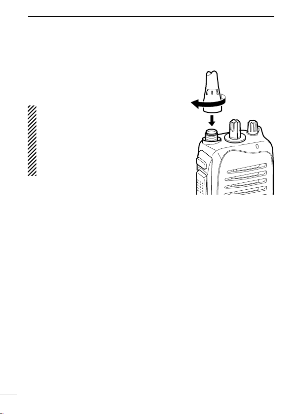
•NE PAS faire fonctionner la radio sans qu’une antenne appropriée y soit
fixée, car ceci risque d’endommager la radio et causer une exposition su-
périeure aux limites établies par la FCC
et d’IC
. L’antenne appropriée est
celle qui est fournie avec cette radio par le fabricant ou une antenne spé-
cialement autorisée par le fabricant pour être utilisée avec cette radio.
• NE PASémettrependantplusde50%dutempstotald’utilisation
del’appareil(«50%dufacteurd’utilisation»).Lanotion«50%dufac-
teurd’utilisation»s’appliqueégalementaumodeVOX/PTT.Émettre
pendantplusde50%dutempstotald’utilisationpeutcauserune
exposition aux RF supérieure aux limites établies par la FCC et d’IC.
Lorsque le voyant DEL rouge s’allume, cette radio est en train d’émet-
tre. La radio émettra si vous appuyez sur le bouton du microphone.
•TOUJOURS tenirl’antenneéloignéed’aumoins2,5cmdevotrecorps
au moment d’émettre et utiliser uniquement l’attache pour ceinture Icom
illustrée à la p. 33, lorsque vous attachez la radio à votre ceinture, ou à
autre chose, de façon à vous assurer de ne pas provoquer une exposi-
tion aux RF supérieure aux limites fixées par la FCC et d’IC. Pour offrir
à vos interlocuteurs la meilleure qualité de transmission possible, tenez
l’antenne à au moins 5 cm de votre bouche et légèrement de côté.
Les renseignements ci-dessus fournissent à l’utilisateur toute l’information néces-
saire sur l’exposition aux RF et sur ce qu’il faut faire pour assurer que cette radio
fonctionne en respectant les limites d’exposition aux RF établies par la FCC et d’IC.
Interférence électromagnétique et compatibilité
En mode de transmission, votre radio Icom produit de l’énergie de RF
qui peut provoquer des interférences avec d’autres appareils ou sys-
tèmes. Pour éviter de telles interférences, mettez la radio hors tension
dans les secteurs où une signalisation l’exige. NE PAS faire fonctionner
l’émetteur dans des secteurs sensibles au rayonnement électromagné-
tique tels que les hôpitaux, les aéronefs et les sites de dynamitage.
Usage professionnel/contrôlé
Ce radio émetteur est utilisé dans des cas où des personnes sont expo-
sées en raison de leur travail, pourvu qu’elles soient conscientes du risque
d’exposition et qu’elles puissent exercer un contrôle sur cette exposition.

v
FOREWORD
READ ALL INSTRUCTIONS carefully and completely before
using the transceiver.
SAVE THIS INSTRUCTION MANUAL— This instruction
manualcontainsimportantoperatinginstructionsfortheIC-F3011/
IC-F3013vhf transceiversandIC-F4011/IC-F4013uhf trans-
c e i v e r s .
EXPLICITDEFINITIONS
WORD DEFINITION
RDANGER! Personal death, serious injury or an explo-
sion may occur.
RWARNING! Personal injury, fire hazard or electric shock
may occur.
CAUTION Equipment damage may occur.
NOTE
If disregarded, inconvenience only. No risk
of personal injury, fire or electric shock.
Icom, Icom Inc. and the Icom logo are registered trademarks of Icom Incorpo-
rated(Japan)inJapan,theUnitedStates,theUnitedKingdom,Germany,France,
Spain,Russiaand/orothercountries.

vi
RDANGER! NEVER short the terminals of the battery pack.
RDANGER! Use and charge only specified Icom battery packs
with Icom radios or Icom chargers. Only Icom battery packs are
tested and approved for use with Icom radios or charged with Icom
chargers. Using third-party or counterfeit battery packs or chargers
may cause smoke, fire, or cause the battery to burst.
RWARNING! NEVER hold the transceiver so that the an-
tenna is very close to, or touching exposed parts of the body,
especially the face or eyes, while transmitting. The transceiver will
performbestifthemicrophoneis5to10cm(2to4in.)awayfrom
the lips and the transceiver is vertical.
RWARNING! NEVER operate the transceiver with a headset
or other audio accessories at high volume levels.
CAUTION: NEVER
expose the transceiver to rain, snow or any
liquids. The transceiver may be damaged.
DO NOT push [PTT] when not actually desiring to transmit.
DO NOT use or place the transceiver in direct sunlight or in areas
withtemperaturesbelow–30°C(+22°F)orabove+60°C(+140°F).
DO NOT modify the transceiver. The transceiver warranty does
not cover any problems caused by unauthorized modification.
MAKE SURE the flexible antenna and battery pack are securely
attached to the transceiver, and that the antenna and battery pack
are dry before attachment. Exposing the inside of the transceiver
to water will result in serious damage to the transceiver.
For U.S.A. only
CAUTION: Changes or modifications to this device, not expressly
approved by Icom Inc., could void your authority to operate this
transceiver under FCC regulations.
PRECAUTIONS

vii
TABLEOFCONTENTS
SAFETY TRAINING INFORMATION.................................................... i
INFORMATION EN MATIÈRE DE SÉCURITÉ....................................iii
FOREWORD ....................................................................................... v
EXPLICITDEFINITIONS..................................................................... v
PRECAUTIONS.................................................................................. vi
TABLEOFCONTENTS......................................................................vii
1 ACCESSORIES ......................................................................... 1–5
■ Supplied accessories.................................................................. 1
■ Accessory attachments .............................................................. 2
2 PANEL DESCRIPTION ............................................................ 6–11
■ Front, top and side panels .......................................................... 6
■ LED indicator .............................................................................. 8
■ Programmable function keys ......................................................9
3 CONVENTIONAL OPERATION............................................. 12–15
■ Turning power ON.....................................................................12
■ Channel selection ..................................................................... 12
■ Receiving and transmitting ....................................................... 13
■ Setting the squelch level........................................................... 15
4 SIGNALING OPERATIONS ................................................... 16–17
■ Call procedure .......................................................................... 16
■ Emergency Call ........................................................................ 17
■ DTMF transmission................................................................... 17
5 BATTERY CHARGING .......................................................... 18–25
■ Caution ..................................................................................... 18
■Batterychargers ....................................................................... 21
6 BATTERY CASE .................................................................... 26–27
■Optionalbatterycase(BP-240) ................................................ 26
7 SWIVEL BELT CLIP .............................................................. 28–31
■MB-93contents......................................................................... 28
■ To attach ................................................................................... 28
■ To detach .................................................................................. 30
8 OPTIONS ............................................................................... 32–35
9 FCC INFORMATION .................................................................... 36

1
1
ACCESSORIES
■Supplied accessories
The following accessories are supplied.
Flexible
antenna*
Battery pack Battery carger
(with AC adapter)
Belt clip Jack cover (with screws)
*This illustration is described
with the VHF type.
1

2
1ACCESSORIES
■Accessory attachments
DFlexible antenna
Connect the supplied flexible antenna to
the antenna connector.
CAUTION:
•NEVER carry the transceiver by
holding only the antenna.
•DO NOT connect the antenna other
thanlistedonpage34.
•Transmitting without an antenna
may damage the transceiver.

3
1
ACCESSORIES
DBattery pack
To attach the battery pack:
Slide the battery pack on the back of the transceiver in the direction
ofthearrow(q),thenlockitwiththebatteryreleasebutton.
•Slidethebatterypackuntilthebatteryreleasebuttonmakesa‘click’
sound.
To remove the battery pack:
Pushthebatteryreleasebuttoninthedirectionofthearrow(w)as
shown below. The battery pack is then removed.
NOTE:Keepthebatteryterminalsclean.It’sagoodideatooc-
casionally clean them.
NEVER remove or attach the battery pack when the transceiver
is wet or soiled. This may result in water or dust getting into the
transceiver/batterypackandmayresultinthetransceiverbeing
damaged.
q
w
Battery release
button
1

4
1ACCESSORIES
DJack cover
Attach the jack cover when the optional speaker-microphone is not
used.
To attach the jack cover:
qAttach the jack cover to the
[SP MIC] connector.
wTighten the screws.
To detach the jack cover:
eRemove the screws with a
phillips screwdriver.
rDetach the jack cover for the
optional equipment connec-
tion.
e
e
r
w
w
q

5
1
ACCESSORIES
DBelt clip
To attach the belt clip:
qRemove the battery pack if it is attached.
wSlide the belt clip in the direction of the arrow until the belt clip is
lockedandmakesa‘click’sound.
To detach the belt clip:
qRemove the battery pack if it is attached.
wPinchtheclip(q),andslidethebeltclipinthedirectionofthe
arrow(w).
q
w
1

6
2PANEL DESCRIPTION
■Front, top and side panels
Microphone
Speaker
r
w
e
y
u
i
t
q
qCHANNEL SELECTOR
Rotate the channel selector to select the pre-programmed mem-
ory channels.
wVOLUME CONTROL [VOL]
RotatetoturnthepowerON/OFFandadjusttheaudiolevel.

7
2
PANEL DESCRIPTION
eLED INDICATOR(p.8)
➥Lights red while transmitting.
➥Lights green while receiving a signal, or when the squelch is
open.
➥Lights/blinksorangewhenthematched2/5-tonecodeisre-
ceived,accordingtothepre-programming.(ForIC-F3013/
F4013only)
rSPEAKER-MICROPHONE CONNECTOR [SP MIC]
Connects the optional speaker-microphone, earphone, etc.
[SP MIC] jack cover
NOTE: Attach the [SP MIC] jack
cover when the optional equip-
ment is not used. (p. 4)
tDEALER-PROGRAMMABLE KEY [Lower]
Thedesiredfunctioncanbeassignedbyyourdealer.(p.9)
yPTT SWITCH [PTT]
Push and hold to transmit; release to receive.
uDEALER-PROGRAMMABLE KEY [Upper]
Thedesiredfunctioncanbeassignedbyyourdealer.(p.9)
iANTENNA CONNECTOR
Connects the supplied antenna.
2

8
2PANEL DESCRIPTION
■LED indicator
The LED indicator indicates several information
as follows;
(Ref.;R=Red,G=Green,O=Orange)
R R R R
G G G G
G G
R O R O R O R O R O R O R O R O
G
G G
O O
O O
R
•TX:TurnsRedwhiletransmittingasignal.
•RX:TurnsGreenwhilereceivingasignal.
For IC-F3013/IC-F4013 only
•CallLED(ON):Whenreceivingamatched2/5-tone.
•CallLED(Blink):Whenreceivingamatched2/5-tone.
•Fast/Slowscan:BlinkswhileFast/Slowscanisactivated.
•LowBATT1:Youshouldchargethebattery.(blinksslowly)
•LowBATT2:Youmustchargethebattery.(blinksfast)
•TXlowBATT2:LowBATT2wasdetectedduringTXmode.
•CHerror:Non-programmedchannelisselected.

9
2
PANEL DESCRIPTION
■Programmable function keys
The following functions can be assigned to [Upper] and [Lower]
programmable function keys.
Consult your Icom dealer or system operator for details concerning
your transceivers programming.
DFor All models
SCAN A KEY
➥Push to start and cancel scanning operation.
➥When the Power ON scan function is turned ON, push to pause
the scanning operation.The paused scan restarts after the spec-
ified time period has passed.
SCAN B KEY
Push to start and cancel scanning operation. In case of transmis-
sion during scan, pauses scanning. The paused scan restarts after
the specified time period has passed.
PRIORITY CHANNEL KEYS
➥PushtoselectthePriorityAorPriorityBchannel.
➥Push and hold [Prio A (Rewrite)] to rewrite the Prio A channel.
MR-CH 1/2/3/4 KEYS
Pushtoselectamemorychannels1to4directly.
2

10
2PANEL DESCRIPTION
OUTPUT POWER SELECTION KEY
Select the transmit output power temporarily or permanently, de-
pending on the pre-setting.
•Askyourdealerfortheoutputpowerlevelforeachselection.
TALK AROUND KEY
➥Push to turn the talk around function OFF.
➥Push and hold to turn the talk around function ON.
•Thetalkaroundfunctionequalizesthetransmitfrequencytothe
receive frequency for transceiver-to-transceiver communication.
WIDE/NARROW KEY
➥Push to select the IF bandwidth to wide.
•Thewidepassbandwidthcanbeselectedfrom25or20kHzusing
theoptionalcloningsoftware(PMRoperationonly).Askyourdealer
for details.
➥Push and hold to select the IF bandwidth to narrow.
SIREN KEY
Push to emit a siren. This function can be used for situations other
than an emergency alert such as a security alarm for example.
LOCK KEY
Push and hold to electronically lock all programmable keys except
the followings:
[Moni(Audi)], [Call](incl.CallAandCallB)*and
[Emergency Single]/[Emergency Repeat]
(incl.Silent)*.
*AvailableforIC-F3013/IC-F4013only.

11
2
PANEL DESCRIPTION
MONITOR KEY
➥PushtomuteandreleasetheCTCSS(DTCS)or2Tone*squelch
mute.Openanysquelches/deactivateanymuteswhilepushing
this key. (LMRoperationonly)
*AvailablefortheIC-F3013/F4013only.
➥Activatesoneof(ortwoof)thefollowingfunctionsoneachchan-
nel independently: (PMRoperationonly)
•Pushandholdtoun-mutethechannel(audioisemitted;‘Audible’).
•Pushtomutethechannel(audioisnotemitted;‘Inaudible ).
•Pushtosenda‘resetcode’afterthecommunicationisnished.
NOTE:Theun-mutecondition(‘Audible’condition)mayauto-
maticallyreturntothemutecondition(‘Inaudible’condition)
after a specified period.
DFor IC-F3013/IC-F4013 only
DTMF AUTODIAL KEY
Push to transmit the programmed DTMF code.
CALL KEYS
Pushtotransmita2/5-tonecode.
•Calltransmissionisnecessarybeforeyoucallanotherstationdepend-
ing on your signalling system.
•[CallA]and/or[CallB]keysmaybeavailablewhenyoursystemem-
ploysselective‘Individual/Group’calls.Askyourdealerwhichcallis
assigned to each key.
EMERGENCY SINGLE/EMERGENCY REPEAT KEYS
➥Push and hold for the specified time period to transmit an emer-
gency call once or repeatedly.
➥
When [Emergency Single (Silent)] or [Emergency Repeat (Silent)]
is pushed, an emergency call is transmitted with no beep emission.
•Ifyouwanttocanceltheemergencycall,push(orpushandhold)
the key again before transmitting the call.
•Theemergencycallistransmittedonetimeonlyorrepeatedlyuntil
receiving a control code depending on the pre-setting.
2

12
3
CONVENTIONAL OPERATION
■Turning power ON
Rotate [VOL] to turn power ON.
■Channel selection
Rotate [CHANNEL SELECTOR] to se-
lect the desired operating channel, in
sequence; or, push one of [MR-CH 1] to
[MR-CH 4] key to select a channel di-
rectly.
AUTOMATIC SCAN TYPE:
Channel setting is not necessary for this
type. When turning the power ON, the
transceiver automatically starts scanning.
Scanning stops when receiving a call.
[VOL]
[CHANNEL
SELECTOR]
Other manuals for iF3011
1
This manual suits for next models
7
Table of contents
Other Icom Transceiver manuals

Icom
Icom IC-2200H User manual

Icom
Icom IC-M11 User manual

Icom
Icom IC-F3011 Installation and operating instructions

Icom
Icom IC-W32A User manual

Icom
Icom IC-M5 User manual

Icom
Icom IC-4SAT User manual

Icom
Icom IC-M73 User manual

Icom
Icom IC-M35 User manual

Icom
Icom IC-F3030 Series User manual

Icom
Icom IC-F61M User manual
Popular Transceiver manuals by other brands

Yaesu
Yaesu FTV-700 instruction manual

BWI Eagle
BWI Eagle AIR-EAGLE XLT PLUS Product information bulletin

Kenwood
Kenwood VHF P25 Transceiver TK-5710 instruction manual

Schluter Systems
Schluter Systems FS2001F-ISO user manual

Vertex Standard
Vertex Standard VX-4200 Series Service manual

Yaesu
Yaesu FT-1000 operating manual