ICP DAS USA GTM-201 Series User manual

GTM-201 Series User Manual
Publication Jul, 2013 Ver.1.06
1
Industrial Quad-band GPRS/GSM Modem
GTM-201 Series
User Manual
Warranty
All products manufactured by ICP DAS are warranted against
defective materials for a period of one year from the date of delivery
to the original purchaser.
Warning
ICP DAS assumes no liability for damages consequent to the
use of this product. ICP DAS reserves the right to change this
manual at any time without notice. The information furnished by ICP
DAS is believed to be accurate and reliable. However, no
responsibility is assumed by ICP DAS for its use, or for any
infringements of patents or other rights of third parties resulting from
its use.
Copyright
Copyright 2009 by ICP DAS Co., LTD. All rights reserved
worldwide.
Trademark
The names used for identification only may be registered
trademarks of their respective companies.
www.ipc2u.ru www.icp-das.ru
www.ipc2u.de www.ipc2u.com
ГК Атлант Инжиниринг – официальный представитель вРФ иСНГ

GTM-201 Series User Manual
Publication Jul, 2013 Ver.1.06
2
Table of Contents
Chapter 1 Introduction ....................................................3
Chapter 2 Hardware Specifications ...............................4
2.1 GTM-201 Series ........................................................................4
2.2 GTM-201 Specifications .........................................................5
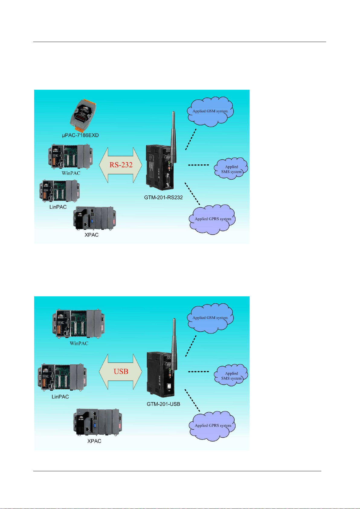
Chapter 3 Application architecture................................7
3.1 Application 1..............................................................................7
3.2 Application 2..............................................................................7
3.3 Application 3..............................................................................8
3.4 Application 4..............................................................................8
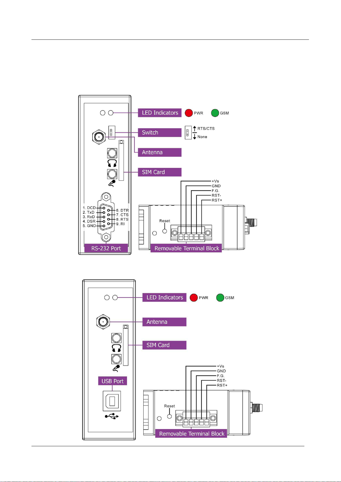
Chapter 4 Hardware Appearance ...................................9
4.1 View of the GTM-201-RS232 and GTM-201-USB Panel..9
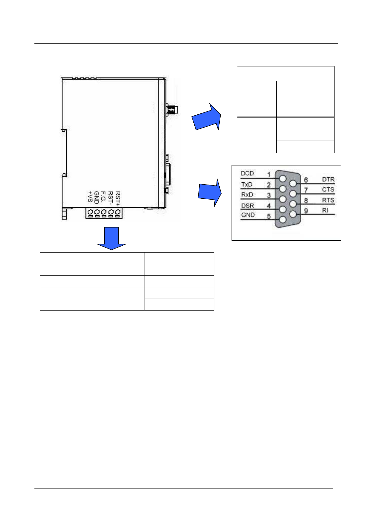
4.2 Pin Assignments ....................................................................10
4.3 Hardware Dimensions ..........................................................11
4.4 LED indicators ........................................................................12
Chapter 5 Hardware Wire Connection .........................13
5.1 Reset Wire Connection.........................................................13
5.2 GSM/GPRS Installation.........................................................14
5.3 Quick Test ................................................................................15
Chapter 6 GPRS connection.........................................21
6.1 XPAC –8000 (Microsoft Windows XP) .............................21
6.2 WinPAC-8000 (WinCE) ..........................................................36
6.3 LinPAC –8000 (Linux) ..........................................................47
Chapter 7 USB driver installation ................................51
7.1 XPAC –8000 (Microsoft Windows XP) .............................51
7.2 WinPAC –8000 (WinCE).......................................................59
7.3 LinPAC –8000 (Linux) ..........................................................60
Chapter 8 Software Reset .............................................61
8.1 Software Reset (for GTM-201-RS232)...............................61
www.ipc2u.ru www.icp-das.ru
www.ipc2u.de www.ipc2u.com
ГК Атлант Инжиниринг – официальный представитель вРФ иСНГ

GTM-201 Series User Manual
Publication Jul, 2013 Ver.1.06
3
Chapter 1 Introduction
The GTM-201 series are industrial Quad-band GSM/GPRS modems with RS-232 and USB
interfaces that work on frequencies of GSM 850 MHz, EGSM 900 MHz, DCS 1800 MHz and PCS
1900 MHz. The modems utilize the GSM/GPRS network for convenient and inexpensive data
transfer from remote instruments, meters, computers or control systems in either live data or packet
data. GTM-201 series have the integrated TCP/IP stack so that even simple controllers with serial
communications ports can be connected to the modem without the need for special driver
implementation. With the features of GTM-201 series, the systems can be SMS and GPRS
connection applications with various PLC and PC. Moreover, with the voice interface, these
modems can also be applied to the alarm system with sounds.
www.ipc2u.ru www.icp-das.ru
www.ipc2u.de www.ipc2u.com
ГК Атлант Инжиниринг – официальный представитель вРФ иСНГ

GTM-201 Series User Manual
Publication Jul, 2013 Ver.1.06
4
Chapter 2 Hardware Specifications
2.1 GTM-201 Series
Model: GTM-201-RS232
Model: GTM-201-USB
www.ipc2u.ru www.icp-das.ru
www.ipc2u.de www.ipc2u.com
ГК Атлант Инжиниринг – официальный представитель вРФ иСНГ

GTM-201 Series User Manual
Publication Jul, 2013 Ver.1.06
5
2.2 GTM-201 Specifications
Models
GTM-201-RS232
GTM-201-USB
GSM/GPRS System
GPRS/GSM
Quad-band
850/900/1800/1900 MHz
GPRS Multi-slot
Class 10/8
GPRS Mobile
Station
Class B
GPRS Class 10
Max. download speed 85.6 kbps
CSD
Up to 14.4 kbps
Compliant to GSM
Phase 2/2+
Class 4 (2 W @ 850/900 MHz); Class 1 (1 W @ 1800/1900 MHz)
Coding Schemes
CS 1, CS 2, CS 3, CS 4
SMS
Text and PDU Mode
Serial Ports
Serial Standards
RS-232 (DB9 Female)
USB (B-TYPE) to RS232(VCP)
RS-232
TxD, RxD, RTS, CTS, DTR,
DSR, DCD, RI, GND
TxD, RxD, DTR, DSR, DCD, RI,
GND
Baud Rate
9600 bps ~ 115200 bps
Include Cable
RS-232 9-Pin Female to Male
cable(CA-0915)
USB Type A to Type B cable
(CA-USB18)
Compatibility
-
USB 1.1 and 2.0 standard
USB Driver
Support
-
Windows 98 and 2000
Windows XP and XP 64-bit
Windows Vista and Vista 64-bit
WinPAC(WinCE 5.0)
LinPAC(Linux kernel 2.6)
Reset Input
Input Type
Isolated, 3750 Vrms
On Voltage Level
+3.5 VDC ~ +30 VDC
Off Voltage Level
+1V max.
Input Impedance
3 kΩ, 0.25 W
LED Indicators
Power
Red color
GSM/GPRS
Green color
Power
Protection
Power reverse polarity protection
www.ipc2u.ru www.icp-das.ru
www.ipc2u.de www.ipc2u.com
ГК Атлант Инжиниринг – официальный представитель вРФ иСНГ

GTM-201 Series User Manual
Publication Jul, 2013 Ver.1.06
6
Frame Ground
Protection
ESD, Surge, EFT, Hi-Pot
Required Supply
Voltage
+10 VDC ~ +30 VDC
Power
Consumption
Idle: 25 mA @ 24 VDC; Data Link: 100 ~ 400 mA (peak) @ 24 VDC
Connection
5-Pin 3.81 mm Removable Terminal Block
Mechanical
Casing
Plastic
Flammability
UL 94V-0 materials
Dimensions
(W x L x H)
33 mm x 87 mm x 107 mm
Installation
DIN-Rail
Environment
Operating
Temperature
-25 °C ~ +55 °C
Storage
Temperature
-40 °C ~ +80 °C
Humidity
5 ~ 95% RH, non-condensing
Note1: The baud rate of GTM-201-RS232 and GTM-201-USB are default in
115200 bps.
www.ipc2u.ru www.icp-das.ru
www.ipc2u.de www.ipc2u.com
ГК Атлант Инжиниринг – официальный представитель вРФ иСНГ

GTM-201 Series User Manual
Publication Jul, 2013 Ver.1.06
7
Chapter 3 Application architecture
3.1 Application 1
3.2 Application 2
www.ipc2u.ru www.icp-das.ru
www.ipc2u.de www.ipc2u.com
ГК Атлант Инжиниринг – официальный представитель вРФ иСНГ

GTM-201 Series User Manual
Publication Jul, 2013 Ver.1.06
8
3.3 Application 3
3.4 Application 4
www.ipc2u.ru www.icp-das.ru
www.ipc2u.de www.ipc2u.com
ГК Атлант Инжиниринг – официальный представитель вРФ иСНГ

GTM-201 Series User Manual
Publication Jul, 2013 Ver.1.06
9
Chapter 4 Hardware Appearance
4.1 View of the GTM-201-RS232 and GTM-201-USB Panel
GTM-201-RS232 :
GTM-201-USB :
www.ipc2u.ru www.icp-das.ru
www.ipc2u.de www.ipc2u.com
ГК Атлант Инжиниринг – официальный представитель вРФ иСНГ

GTM-201 Series User Manual
Publication Jul, 2013 Ver.1.06
10
4.2 Pin Assignments
RESET
RST+
RST-
Frame Ground
F.G.
Power Input:
+10 ~ 30VDC
DC.GND
DC.+VS
SW1-Operation Mode
None
No
Handshaking
3-wire RS-232
RTS/CTS
Hardware
Handshaking
9-wire RS-232
www.ipc2u.ru www.icp-das.ru
www.ipc2u.de www.ipc2u.com
ГК Атлант Инжиниринг – официальный представитель вРФ иСНГ

GTM-201 Series User Manual
Publication Jul, 2013 Ver.1.06
11
4.3 Hardware Dimensions
GTM-201-RS232
GTM-201-USB
www.ipc2u.ru www.icp-das.ru
www.ipc2u.de www.ipc2u.com
ГК Атлант Инжиниринг – официальный представитель вРФ иСНГ

GTM-201 Series User Manual
Publication Jul, 2013 Ver.1.06
12
4.4 LED indicators
There are two LED indicators to help users to judge the various conditions of GTM-201.
The description is as follows:
PWR(Red):The PWR LED can indicate the status of Power module.
GSM (Green):The modem LED can indicate the status of GSM module.
Power normal
Power fail
Always on
Always off
Modem normal
Modem fail
Blanking (3 sec)
Off
or
Blanking (not 3 sec)
www.ipc2u.ru www.icp-das.ru
www.ipc2u.de www.ipc2u.com
ГК Атлант Инжиниринг – официальный представитель вРФ иСНГ

GTM-201 Series User Manual
Publication Jul, 2013 Ver.1.06
13
Chapter 5 Hardware Wire Connection
5.1 Reset Wire Connection
Reset Wire Connection
Input Type
Reset State ON
Reset State OFF
Reset
Input
Reset Input
ON Voltage Level
+3.5 VDC ~ +30 VDC
OFF Voltage Level
+1 VDC max.
Timing of restart modem
www.ipc2u.ru www.icp-das.ru
www.ipc2u.de www.ipc2u.com
ГК Атлант Инжиниринг – официальный представитель вРФ иСНГ

GTM-201 Series User Manual
Publication Jul, 2013 Ver.1.06
14
5.2 GSM/GPRS Installation
SIM card Installation
GPRS/GSM Antenna Installation
www.ipc2u.ru www.icp-das.ru
www.ipc2u.de www.ipc2u.com
ГК Атлант Инжиниринг – официальный представитель вРФ иСНГ

GTM-201 Series User Manual
Publication Jul, 2013 Ver.1.06
15
5.3 Quick Test
Hardware installation :
www.ipc2u.ru www.icp-das.ru
www.ipc2u.de www.ipc2u.com
ГК Атлант Инжиниринг – официальный представитель вРФ иСНГ

GTM-201 Series User Manual
Publication Jul, 2013 Ver.1.06
16
Software Installation: (Hyper Terminal)
Step1. Start →All Programs →Accessories →Communications →Hyper Terminal
Step2. If these is a pop-up form that “Default Telent Program?”, please select “Yes”
www.ipc2u.ru www.icp-das.ru
www.ipc2u.de www.ipc2u.com
ГК Атлант Инжиниринг – официальный представитель вРФ иСНГ

GTM-201 Series User Manual
Publication Jul, 2013 Ver.1.06
17
Step3. Input new connection name →Click “OK”
Step4. Select your PC serial port →Click “OK”
www.ipc2u.ru www.icp-das.ru
www.ipc2u.de www.ipc2u.com
ГК Атлант Инжиниринг – официальный представитель вРФ иСНГ

GTM-201 Series User Manual
Publication Jul, 2013 Ver.1.06
18
Step5. Please refer to the following settings
Bits per second
115200
Data bits
8
Parity
None
Stop bits
1
Flow control
None (Note)
Note: Please select “None”mode on the GTM-201-RS232 SW1 Hardware
Step6. File →Properties
www.ipc2u.ru www.icp-das.ru
www.ipc2u.de www.ipc2u.com
ГК Атлант Инжиниринг – официальный представитель вРФ иСНГ

GTM-201 Series User Manual
Publication Jul, 2013 Ver.1.06
19
Step7. Settings →Click “ASCII Setup…”
Step8. Select “Echo typed character locally”→OK
www.ipc2u.ru www.icp-das.ru
www.ipc2u.de www.ipc2u.com
ГК Атлант Инжиниринг – официальный представитель вРФ иСНГ

GTM-201 Series User Manual
Publication Jul, 2013 Ver.1.06
20
Step9. Input “AT”and press “Enter”, then you will receive “AT OK”
www.ipc2u.ru www.icp-das.ru
www.ipc2u.de www.ipc2u.com
ГК Атлант Инжиниринг – официальный представитель вРФ иСНГ
This manual suits for next models
2
Table of contents
Other ICP DAS USA Modem manuals

ICP DAS USA
ICP DAS USA SST-2450 User manual

ICP DAS USA
ICP DAS USA GTM-204M Series User manual

ICP DAS USA
ICP DAS USA GTM-203M-3GWA User manual

ICP DAS USA
ICP DAS USA GTM-204M Series User manual

ICP DAS USA
ICP DAS USA GTM-201-USB Instruction manual

ICP DAS USA
ICP DAS USA RFU-2400 User manual

ICP DAS USA
ICP DAS USA GTM-201-RS232 User manual

ICP DAS USA
ICP DAS USA GTM-200M User manual

ICP DAS USA
ICP DAS USA SST-900B User manual

ICP DAS USA
ICP DAS USA WLS-R01 User manual