ICP DAS USA GTM-204M Series User manual

Industrial 4G Modem
GTM-204M Series
User Manual
Version 1.3.0 March 2018
保固說明
www.ipc2u.ru
www.icp-das.ru
www.ipc2u.com

GTM-204M-4G Series User’s Manual v1.3
Warranty
All products manufactured by ICP DAS are under warranty regarding
defective materials for a period of one year, beginning from the date
of delivery to the original purchaser.
Warning
ICP DAS assumes no liability for any damage resulting from the use of
this product. ICP DAS reserves the right to change this manual at any
time without notice. The information furnished by ICP DAS is believed
to be accurate and reliable. However, no responsibility is assumed by
ICP DAS for its use, not for any infringements of patents or other
rights of third parties resulting from its use.
Copyright
Copyright @ 2017 by ICP DAS Co., Ltd. All rights are reserved.
Trademark
The names used for identification only may be registered trademarks
of their respective companies.
Contact US
If you have any problem, please feel free to contact us. You can count on us for
quick response.
www.ipc2u.ru
www.icp-das.ru
www.ipc2u.com

GTM-204M-4G Series User’s Manual v1.3
Symbol description
RoHS
Manufacture of this product strictly abide by the rules
of lead-free and does not contain any harmful
substances.
WEEE
This symbol means this product must be collected at
the time of discarding in the EU.
HOT SURFACE DO NOT TOUCH
This symbol means this product’s enclosure may be
with high temperature, do not touch before cooling or
else will be burned.
USB
This product support USB 2.0 interface.
www.ipc2u.ru
www.icp-das.ru
www.ipc2u.com

GTM-204M-4G Series User’s Manual v1.3
I
Table of Contents
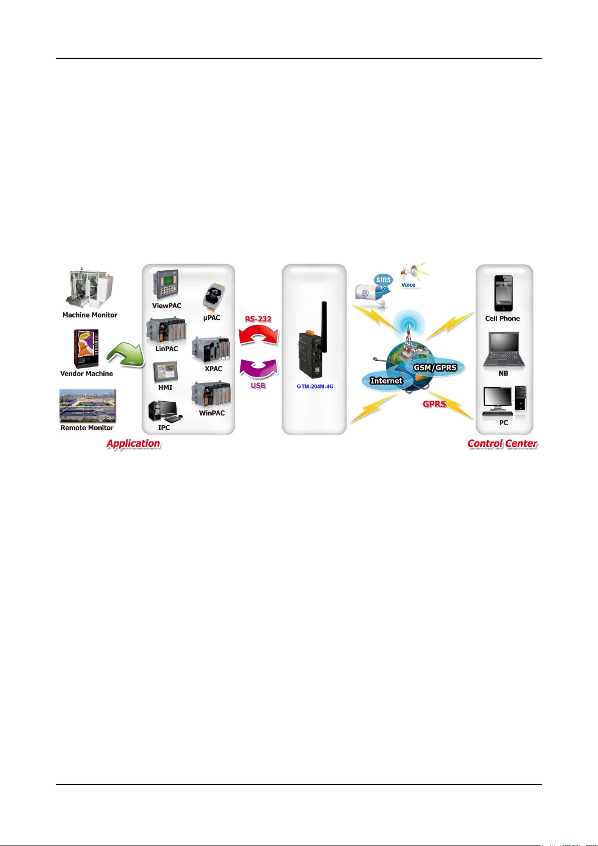
1. Introduction ............................................................................... 1
2. Hardware Specifications........................................................... 2
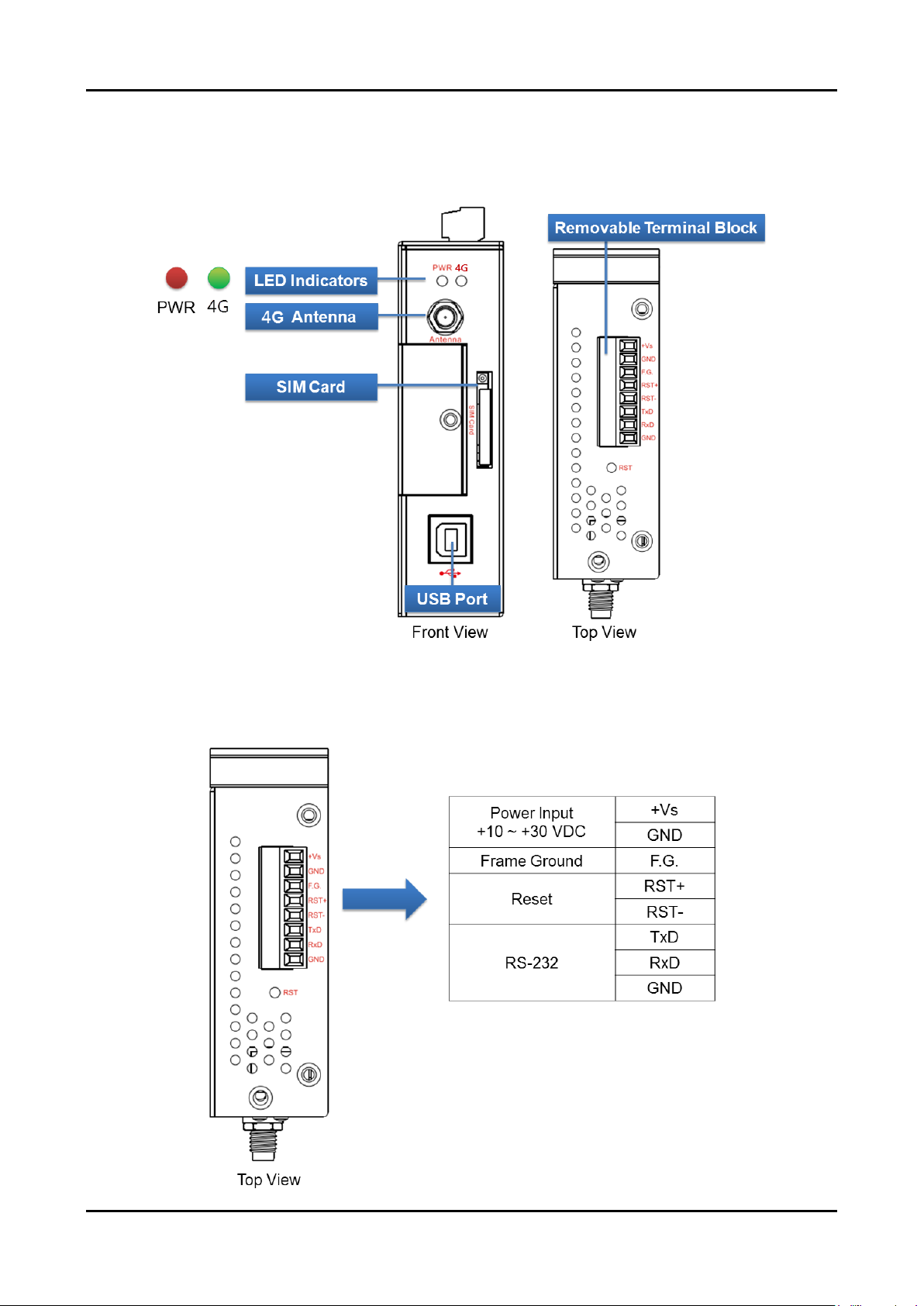
3. Hardware Appearance............................................................... 4
3.1 View of the GTM-204M-4G Panel ......................................................... 4
3.2 Pin Assignments.................................................................................... 4
3.3 LED Indicators....................................................................................... 5
4. Hardware Wire Connection....................................................... 6
4.1 Reset Wire Connection .........................................................................6
4.2 Installation.............................................................................................7
4.3 Quick Test .............................................................................................8
4.3.1 Hardware installation...................................................................8
4.3.2 Software installation (Hyper terminal).......................................... 9
5. GPRS Connection.................................................................... 14
5.1 XPAC-8000 (Microsoft Windows XP) .................................................. 14
5.1.1 GTM-204M-4G Hardware Requirement.................................... 14
5.1.2 Create a New Modem ............................................................... 15
5.1.3 Create a New Dial-up and Networking Connection................... 21
6. USB Driver Installation............................................................ 29
6.1 XPAC-8000 (Microsoft Windows XP) .................................................. 29
7. Revision History ...................................................................... 37
www.ipc2u.ru
www.icp-das.ru
www.ipc2u.com

GTM-204M-4G Series User’s Manual v1.3
- 1/35 -
1. Introduction
The GTM-204M-4GE is an industrial 4G LTE and Quad-band GSM modem with
RS-232 and USB interfaces that work at frequencies of FDD LTE B1/B3/B5/B7/B8/B20 and
WCDMA 850/900/2100 MHz and GSM 850 MHz, EGSM 900 MHz, DCS 1800 MHz , PCS
1900 MHz. The modems utilize the 4G or 3G or GPRS network to transfer data. The
features of the GTM-204M-4GE allow a variety of PLC and PC applications to take
advantage of SMS and 4G or 3G or GPRS connectivity.
www.ipc2u.ru
www.icp-das.ru
www.ipc2u.com

GTM-204M-4G Series User’s Manual v1.3
- 2/35 -
2. Hardware Specifications
Item
GTM-204M-4GE
GTM-204M-4GC
GSM System
Frequency Band
850/900/1800/1900 MHz
900/1800MHz
GPRS Connectivity
GPRS class 12; GPRS station class B
DATA GPRS
Downlink transfer: Max. 85.6 kbps; Uplink transfer: Max 42.8kbps
3G System
Frequency Band (MHz)
WCDMA
850/900/2100
WCDMA 900/2100
TD-SCDMA 1900/2100
CDMA2000 (BC0) 800
Data Transmission
DC-HSPA+ Download: Max. 42 Mbps; Upload: Max 5.76Mbps
TD-SCDMA Download: Max. 4.2 Mbps; Upload: Max 2.2Mbps
CDMA2000 EVDO Download: Max. 14.7 Mbps; Upload: Max 5.4Mbps
4G System
Frequency Band
FDD LTE:
B1/B3/B5/B7/B8/B20
FDD LTE: B1/B3/B8
TDD LTE: B38/B39/B40/B41
Data Transmission
Download Max 100Mbps / Upload Max 50Mbps
SMS
SMS
MT, MO, CB, Text, and PDU mode
Comm. Interface
COM Port
RxD, TxD, GND
COM Port Baud Rate
9600 bps ~ 115200 bps (default:115200 bps)
USB
USB 2.0 (high speed)
USB Driver Support
Windows XP/7/8/10, Windows Server 2012
LED Indicators
Power
Red
3G/GSM
Green
Power
Protection
Power reverse polarity protection
Frame Ground Protection
ESD, Surge, EFT, Hi-Pot
Required Supply Voltage
+10 VDC ~ +30 VDC
Rated Current
30 ~ 15 mA / 10 ~ 30 VDC
Reset Input
Input Type
Isolated, 3750 Vrms
On Voltage Level
+3.5 VDC ~ +30VDC
Off Voltage Level
+1 VDC max.
Input Impedance
3 kΩ, 0.25W
Mechanical
www.ipc2u.ru
www.icp-das.ru
www.ipc2u.com

GTM-204M-4G Series User’s Manual v1.3
- 3/35 -
Casing
Metal
Dimensions (W x L x H)
28 mm x 78.5 mm x 100 mm
Installation
DIN-Rail
Environment
Operation Temperature
-25℃to 70℃
Storage Temperature
-40℃to 80℃
Humidity
5~90% RH, non-condensing
www.ipc2u.ru
www.icp-das.ru
www.ipc2u.com

GTM-204M-4G Series User’s Manual v1.3
- 4/35 -
3. Hardware Appearance
3.1 View of the GTM-204M-4G Panel
3.2 Pin Assignments
www.ipc2u.ru
www.icp-das.ru
www.ipc2u.com

GTM-204M-4G Series User’s Manual v1.3
- 5/35 -
3.3 LED Indicators
There are two LED indicators to help users to judge the various conditions of
GTM-204M-4G. The description is as follows:
A. PWR(Red):The PWR LED can indicate the status of Power module.
Power normal
Power fail
Always ON
Always OFF
B. 4G (Green):The modem LED can indicate the status of GSM module.
4G module normal
4G module fail
Data transmission
ON 2 sec and OFF 1 sec
OFF
or
ON 1 sec and OFF 2
sec
Blinking per 0.2 sec
4G module normal
4G module fail
1
2
3
4
5
6
7
ON
OFF
Time(sec)
ON
OFF
Time(sec)
1
2
3
4
5
6
7
www.ipc2u.ru
www.icp-das.ru
www.ipc2u.com

GTM-204M-4G Series User’s Manual v1.3
- 6/35 -
4. Hardware Wire Connection
4.1 Reset Wire Connection
Input Type
Reset State ON
Reset State OFF
Reset
Input
Reset Input
ON Voltage Level
+3.5 VDC ~ +30 VDC
OFF Voltage Level
+1 VDC max.
www.ipc2u.ru
www.icp-das.ru
www.ipc2u.com

GTM-204M-4G Series User’s Manual v1.3
- 7/35 -
4.2 Installation
GTM-204M-4G should be installed by technical person who should be with the proper
authorization.
GTM-204M-4G should install on the location that general person will not be touch.
SIM card and 4G antenna installation
WARNING! HOT SURFACE DO NOT TOUCH
The product’s enclosure may be with high temperature, do not touch before
cooling or else will be burned.
SAFETY INSTRUCTION NOTES
The unit installation to final system and the DC source (SELV, Limited Power
Source) that is intended to connect with power input pins (DC.+VS / DC.GND)
should be complied with requirements of EN 60950-1. Be sure before connect
to input pins.
www.ipc2u.ru
www.icp-das.ru
www.ipc2u.com

GTM-204M-4G Series User’s Manual v1.3
- 8/35 -
4.3 Quick Test
4.3.1 Hardware installation
www.ipc2u.ru
www.icp-das.ru
www.ipc2u.com

GTM-204M-4G Series User’s Manual v1.3
- 9/35 -
4.3.2 Software installation (Hyper terminal)
Step 1:Start →All Programs →Accessories →Communications →Hyper Terminal
Step 2:If there is a pop-up form that says “Default Telnet Program?”, please select “Yes”
www.ipc2u.ru
www.icp-das.ru
www.ipc2u.com

GTM-204M-4G Series User’s Manual v1.3
- 10/35 -
Step 3:Input new connection name →Click “OK”
Step 4:Select your PC serial port →Click “OK”
www.ipc2u.ru
www.icp-das.ru
www.ipc2u.com

GTM-204M-4G Series User’s Manual v1.3
- 11/35 -
Step 5:Please refer to the following settings
Bits per second
115200
Data bits
8
Parity
None
Stop bits
1
Flow control
None
Step 6:File →Properties
www.ipc2u.ru
www.icp-das.ru
www.ipc2u.com

GTM-204M-4G Series User’s Manual v1.3
- 12/35 -
Step 7:Settings →Click “ASCII Setup…”
Step 8:Select “Echo typed characters locally”→Click “OK”
www.ipc2u.ru
www.icp-das.ru
www.ipc2u.com

GTM-204M-4G Series User’s Manual v1.3
- 13/35 -
Step 9:Input “AT”and press “Enter”, then you will receive “AT OK”
www.ipc2u.ru
www.icp-das.ru
www.ipc2u.com

GTM-204M-4G Series User’s Manual v1.3
- 14/35 -
5. GPRS Connection
5.1 XPAC-8000 (Microsoft Windows XP)
5.1.1 GTM-204M-4G Hardware Requirement
A. GTM-204M-4G (Please install USB driver first)
B. XPAC-8000
C. USB cable
www.ipc2u.ru
www.icp-das.ru
www.ipc2u.com

GTM-204M-4G Series User’s Manual v1.3
- 15/35 -
5.1.2 Create a New Modem
Step 1:Control Panel →Double-click “Phone and Modem Options”
Step 2:Set the area code for the first time →Click “OK”
www.ipc2u.ru
www.icp-das.ru
www.ipc2u.com

GTM-204M-4G Series User’s Manual v1.3
- 16/35 -
Step 3:Control Panel →Double-click “Phone and Modem Options”→Modem →
Click “Add”
Step 4:Select “Don‘t detect my modem; I will select it from a list.”→Click “Next”
www.ipc2u.ru
www.icp-das.ru
www.ipc2u.com
Other manuals for GTM-204M Series
1
This manual suits for next models
1
Table of contents
Other ICP DAS USA Modem manuals

ICP DAS USA
ICP DAS USA GTM-201-RS232 User manual

ICP DAS USA
ICP DAS USA ZT-USBC User manual

ICP DAS USA
ICP DAS USA RFU-433 User manual

ICP DAS USA
ICP DAS USA RFU-433-RU400 User manual

ICP DAS USA
ICP DAS USA WLS-R01 User manual

ICP DAS USA
ICP DAS USA GTM-201-RS232 Instruction manual

ICP DAS USA
ICP DAS USA SST-2450 User manual

ICP DAS USA
ICP DAS USA ZT-2550 User manual

ICP DAS USA
ICP DAS USA SST-900B User manual

ICP DAS USA
ICP DAS USA RFU-2400 User manual