December 14, 2021
6 | P a g e
ICP-M2RV Manual © Copyright 2018 SMICP Pty Ltd - All rights reserved
The ICP-1 can be set up with multiple differing options (E.G. different cylinder sizes,
hopper or inlet feed, and numerous nozzle options to suit your project).
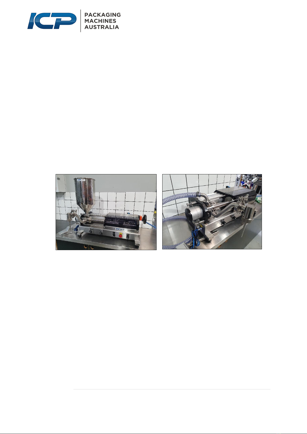
4.1.1 HOPPER
Hopper choice will vary depending on the setup for your machine, from small to
extra-large. If using a hopper, position the hopper’s tri-clover flange onto the seal,
position the tri-clover clamp to enclose the mating inlet port and hopper flanges,
then tighten the clamp finger-tight.
4.1.2 INLET CONNECTION
An inlet connection can be installed to the top of the valve to feed in the product via
a hose. To do this, fit the product hose over the plain end of the curved inlet fitting
and secure it with a hose clamp (Warm the hose in hot water to make this easier).
Then connect the flanged end of the curved inlet fitting to the inlet port.
Note: Ensure that any valves/taps supplying the product are open, and that the hose
is not bent or kinked.
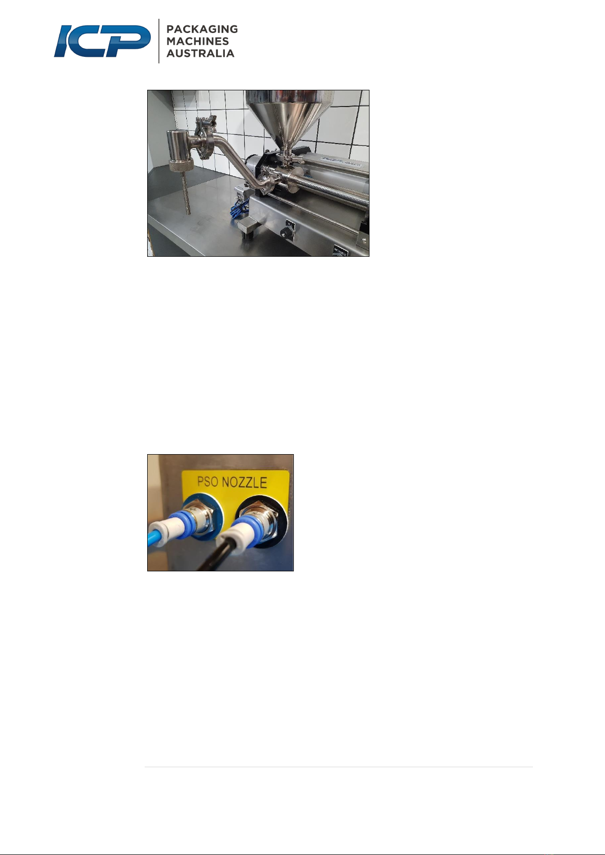
4.1.3 INSTALLING/CHANGING NOZZLES
ICP fillers are available with an extensive range of nozzles to suit a range of
applications. These include;
•Standard Nozzles 6mm –22mm
•Positive Shut Off (PSO) 12mm –25mm inward or outward opening nozzle
•Plug Nozzle
•Suck-back Nozzle 6mm –22mm
Connect the nozzle gooseneck fitting by placing a rubber tri-clover seal ring onto the
outlet port flange on the front of the product valve body, then place the mating
flange of the nozzle gooseneck fitting over the seal. Position a tri-clover clamp to
enclose the flanges and tighten the clamp finger tight.


