4. Commissioning the charging station
7. Connect the Control Pilot (CP) connector to the
red connector cable on the power board (only
necessary in the xed cable version)
8. Remove the insulation of the power supply
and/or xed cable using a wire stripper so that
the cores are sufciently exposed to be able to
be installed in the connecting terminals
9. Slide the rubber ring and the gland on to the
screw connection
10. Tighten the gland until the power supply and/or
xed cable no longer show any movement
11. In the case of a socket version, screw the so-
cket subframe back on the back cover
12. Screw the cover back on the housing
4.1 Safety instructions before operating
Follow the below safety instructions before putting
your charger into operation:
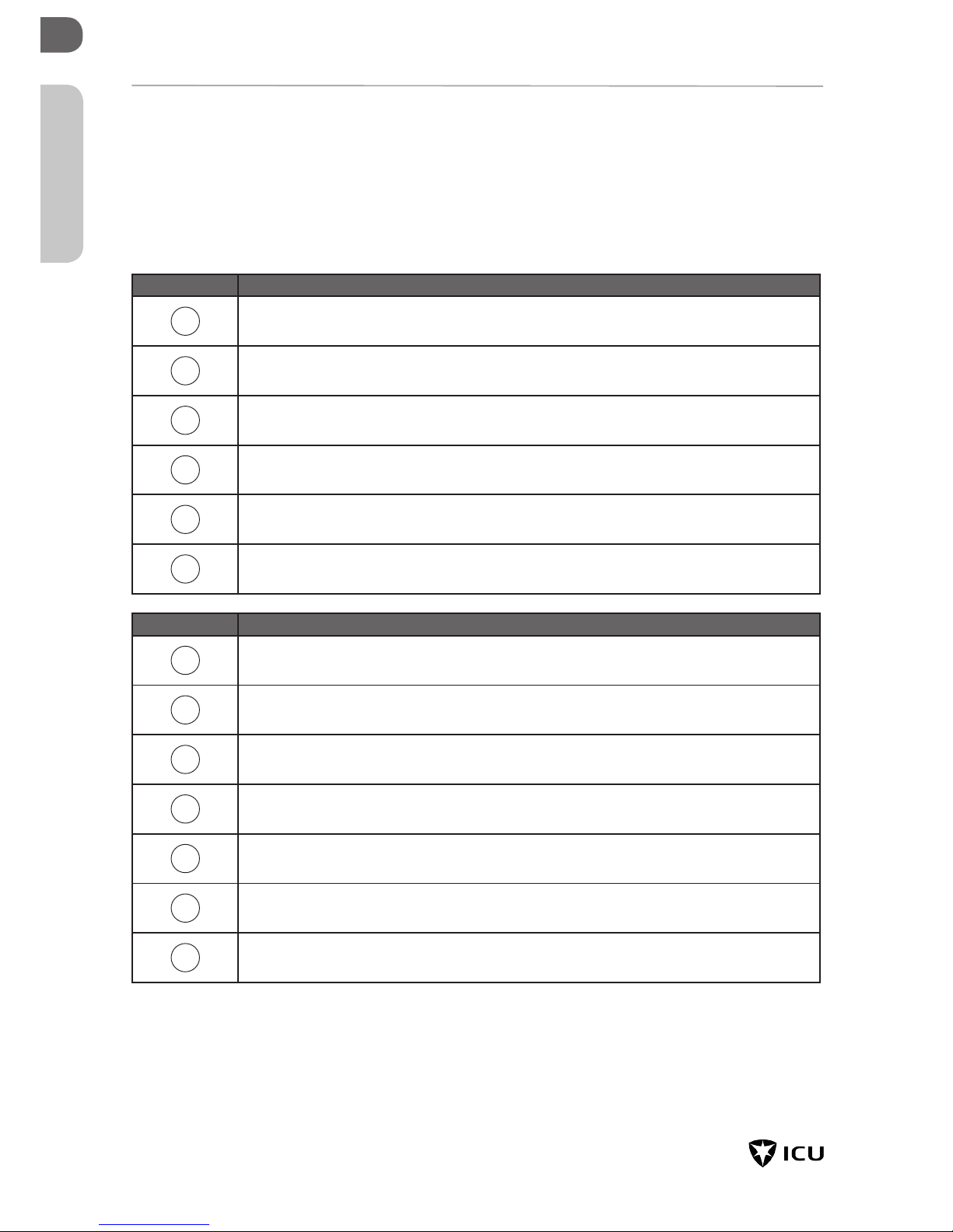
1. Make sure that the charging station is securely
connected to the house supply line as specied
in this manual
2. Make sure that the supply line in the house dis-
tribution is separately protected by an appropri-
ate circuit breaker (B-characteristic)
3. Make sure that the built-in charger or external
upstream RCD is switched on
4. Make sure that the charging station has been
installed in accordance with this guidance
5. Make sure that the housing is always locked in
normal operation
6. Make sure that the charging cable is not twisted
and make sure that cable, charging plug and
housing are free of damage
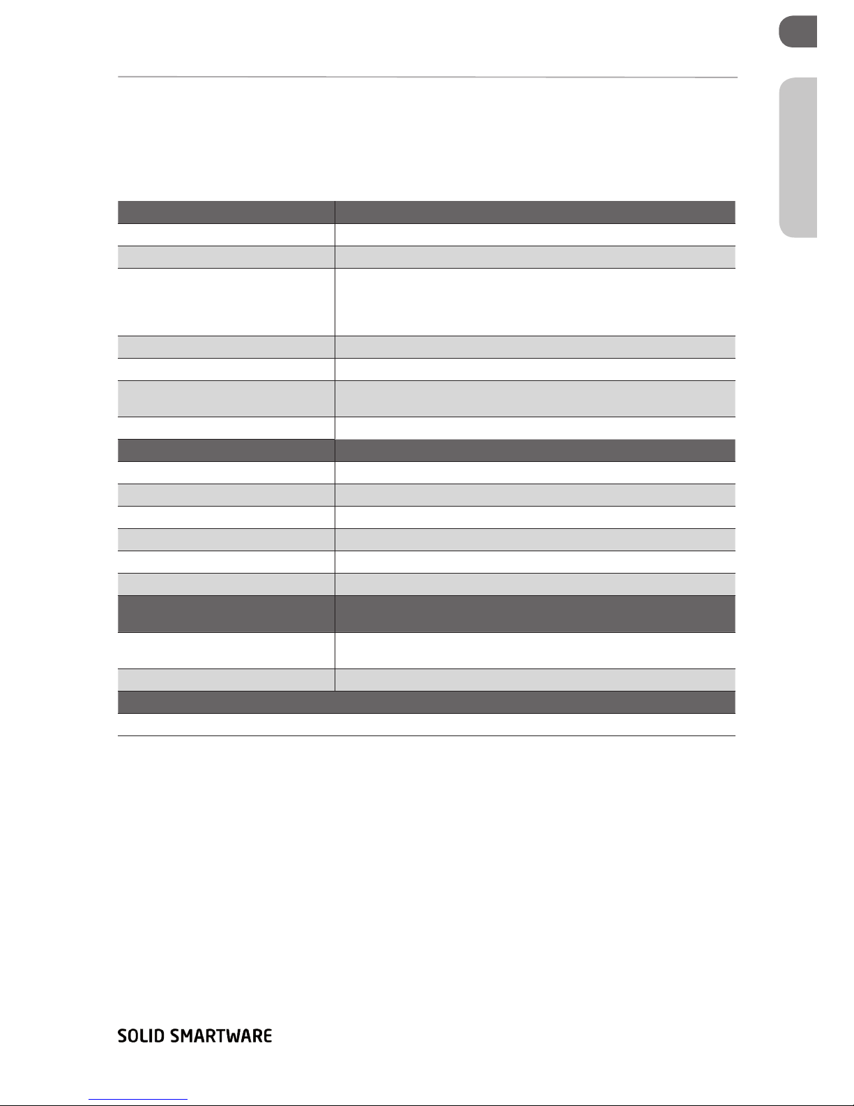
4.2 Putting into operation (with display)
1. Turn on the power at the power supply cable
The charger now performs a self test. The following
actions are performed by the charging station:
1. The door lock is activated
2. The red LED lights up for one second conti-
nuously
3. All LEDs light up for one second continuously
4. The red LED ashes ve times, so that the elec-
tronics are started
5. All LEDs go out
6. The ICU Eve Mini is now ready for charging
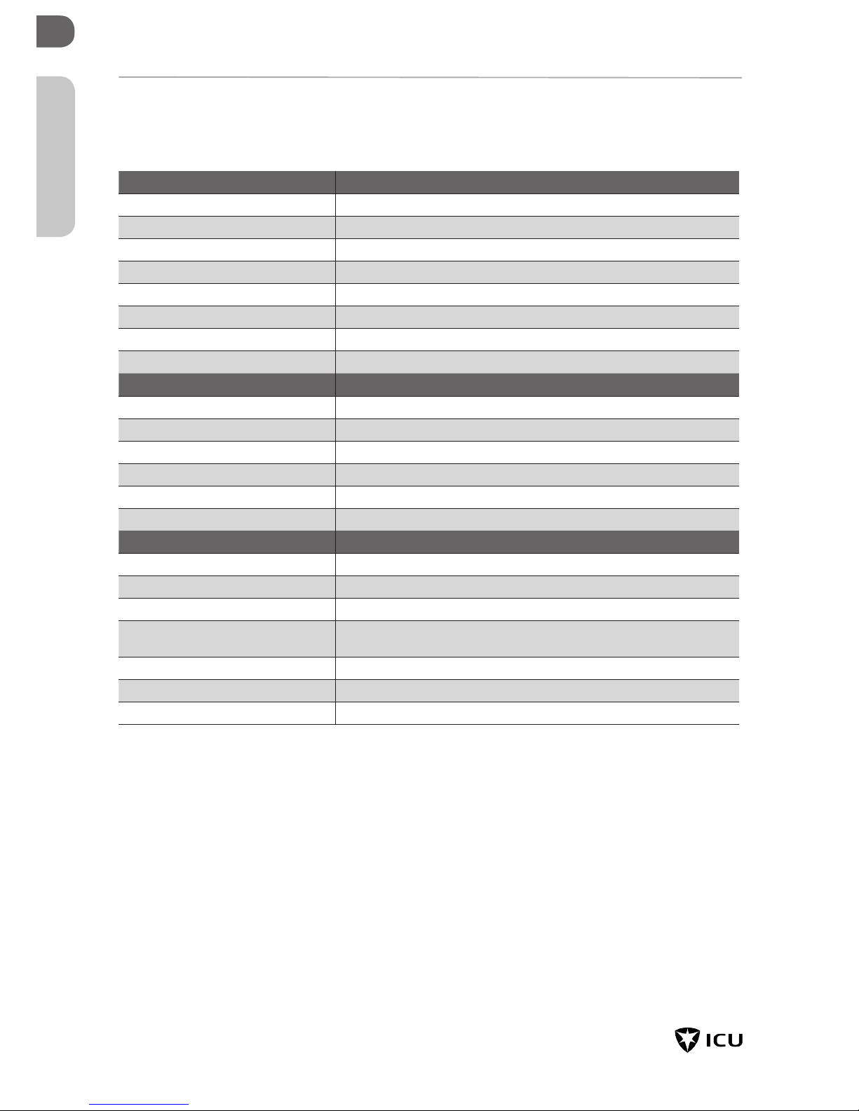
4.3 Putting into operation (without dis-
play)
1. Turn on the power for the power supply cable
The charger now performs a self test. The following
actions are performed by the charging station:
1. The status LED ashes red
2. The ICU Eve Mini is now ready for charging
Commissioning the charging station