4. Thread or push one or two auxiliary contacts and wires through the rear of the connector before inserting into auxiliary housings.
Push into auxiliary housings through rear until notched side of contact tip snaps over spring. Tug wires to make sure wires are secure.
5.SlidetwoauxiliaryPowerpole®housingstogether by dovetails to stack vertically.They cannot be inserted separately into SBE / SBX
housing. The rear of each of the Powerpole housings must be flush.
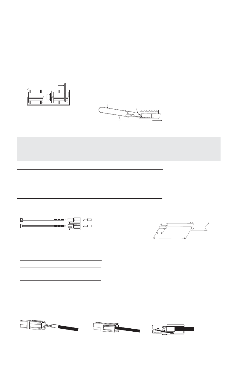
6. Slide stacked auxiliaries back into connector housing until seated. The male dovetail should be on top as shown in (figure 1). Make
sure side grooves of auxiliaries are aligned for retaining pins and insert tubular pins. Tap pins in holes from top, as shown in (figure 1).
7. Cable ties are supplied to secure the auxiliary leads or cable to one of the main power cables. Leave slack or loop in leads to
Powerpole®contacts when applying cable ties. Wraps to be placed approximately 1 inch (25.4 mm) apart as shown in (figure 2).
8. To remove auxiliary housings, punch out retaining pins from bottom of the connector housing with an 0.06 inch (1.5 mm) diameter
steel rod or pin driver. Pull auxiliary housings out of the SBE®/SBX®connector housing. Use contact insertion-extraction tool kit (part
number 111038G2), to remove contacts from auxiliary housings see (figure 3).
WARNING: UTMOST CAUTION SHOULD BE USED WHEN WORKING ON LIVE CONNECTOR CONTACTS
UL and CSAReference - These connectors are recognized under the component program of Underwriters’ Laboratories, File E26226,
as well as Canadian StandardsAssociation, Report LR25154.
© 2019Anderson Power Products, Inc. All rights reserved. APP®,A®,Anderson Power Products®, SBE®, SBX®, SBO®, Powerpole®and
theAPPLogoareregistered trademarksofAndersonPower Products,Inc. Anderson™isa trademarkofAndersonPower Products,Inc.
Anderson™ will use reasonable efforts to include accurate and up-to-date content in the assembly instruction. All product information
contained in the instruction sheet including ordering information, illustrations, specifications, and dimensions, are believed to be reliable
as of the date of publishing, but is subject to change without notice.Anderson™ makes no warranty or representation as to its accuracy.
Contentinthe instruction sheet maycontaintechnicalinaccuracies,typographical errors and may bechangedorupdatedwithout notice.
Anderson™ may also make improvements and/or changes to the products and/or to the programs described in the content at any time
without notice. Current sales drawings and specifications are available upon request.
HEADQUARTERS: AndersonPower Products®,13Pratts Junction Road, Sterling, MA01564-2305 USA www.andersonpower.com
All Data Subject To Change Without Notice 2019-0013, 1S6556 REV 4
Retaining Pin
Top
Male Dovetail
Figure 1
Loop Wire
[25]
1.0
Figure 2
Figure 3