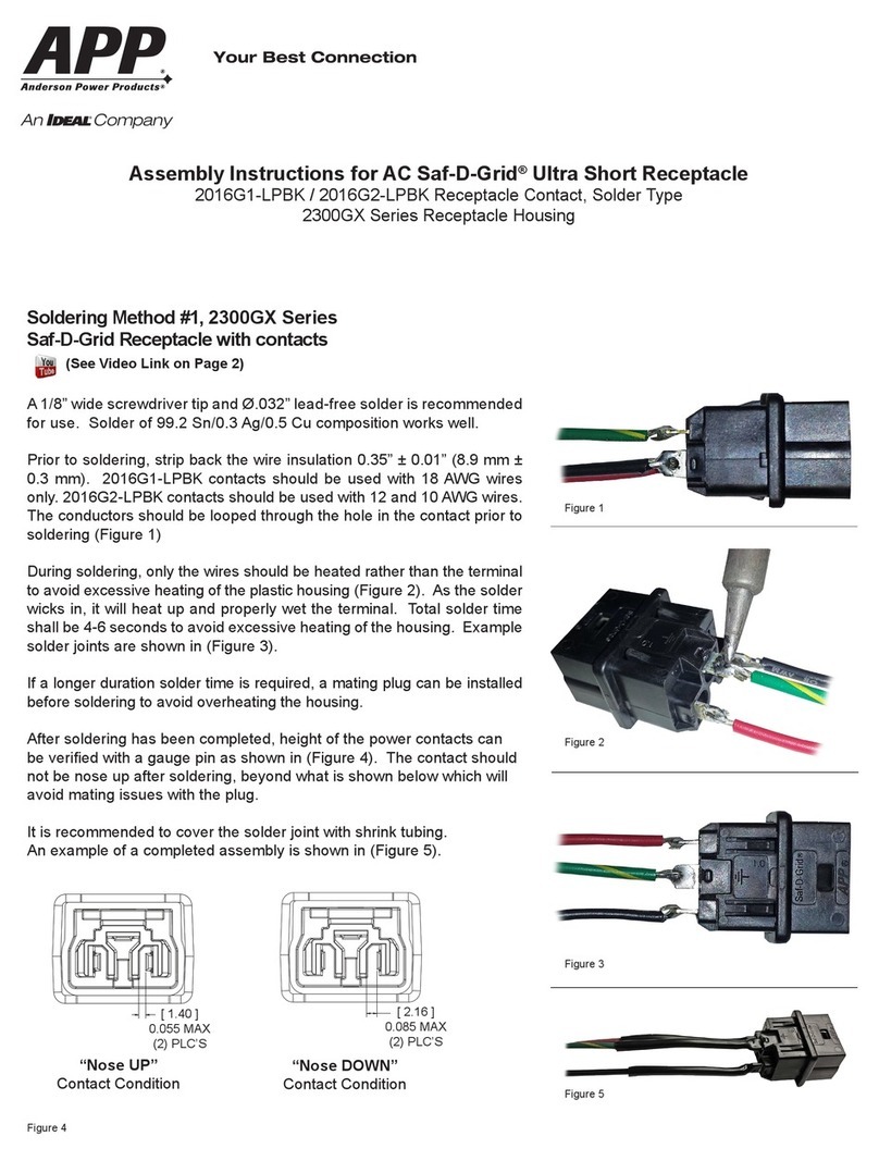
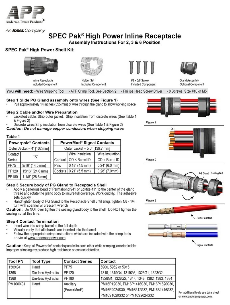
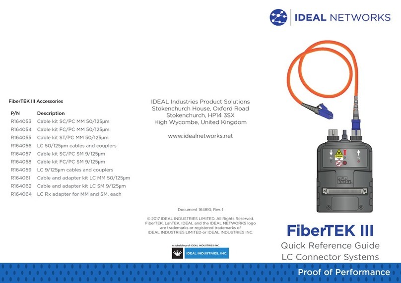
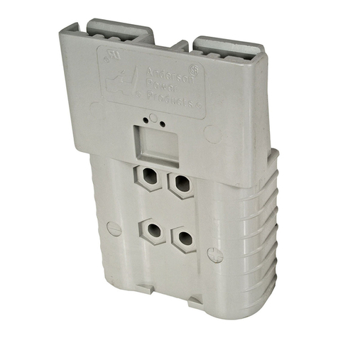
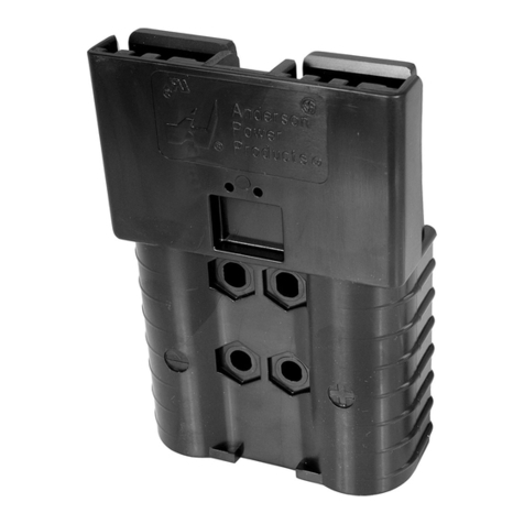
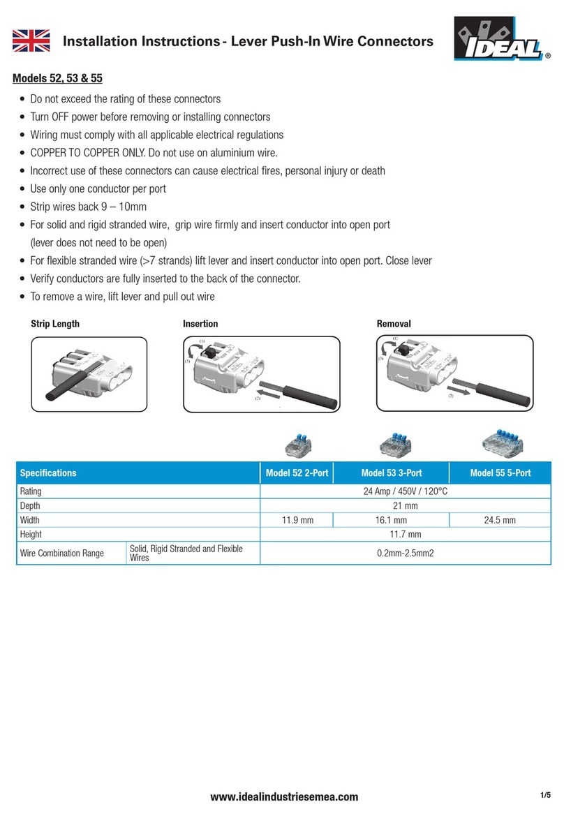
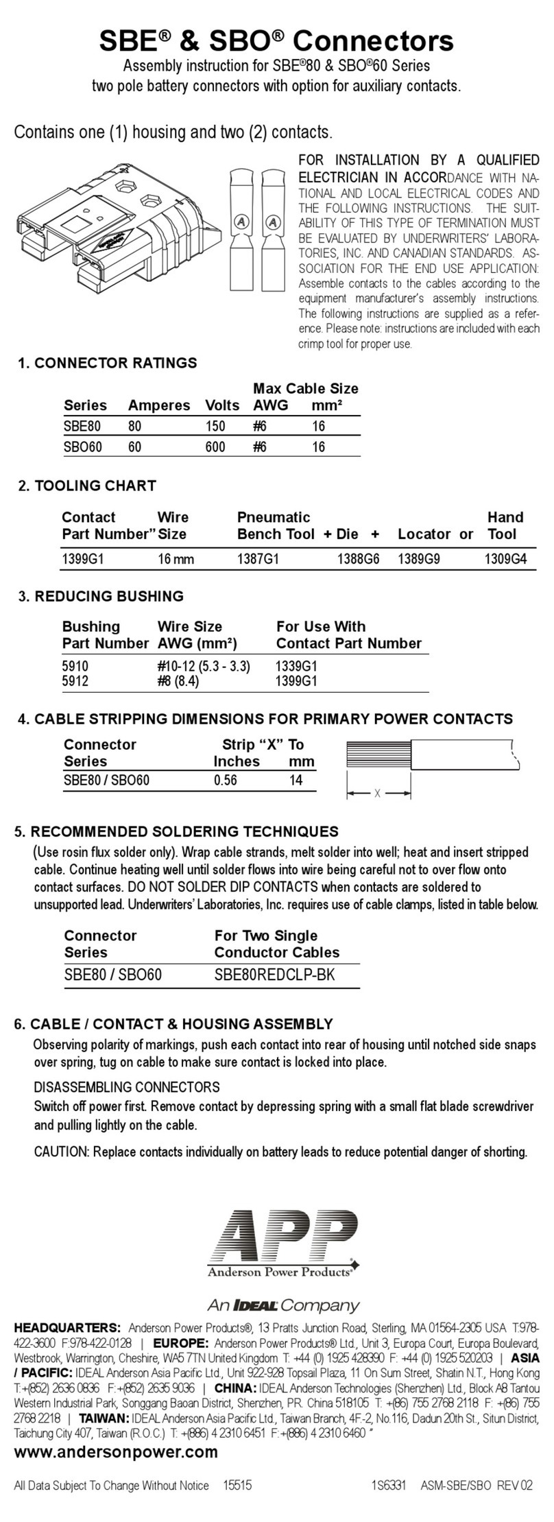
IDEAL APP SBS Series User manual

SBS®Connector
AssemblyInstruction
SBS®50 SBS®75X SBS®75G
The following instructions are supplied as a reference. For installation by a qualified electrician in accordance with national and local
electrical codes and the equipment manufacturer’s assembly instruction. The suitability of this type of termination must be evaluated by
the Underwriter’s Laboratories, Inc. and Canadian Standard Association for the end use application.
SBS®crimp contacts are for use with stranded Copper (Cu) wire only. Crimp tools recommended by APP®are required to achieve the
designed performance of the connector. Use of solid wires, alternate conductor materials, or tools not recommended by Anderson can
affect safety agency approvals of the connector and may produce unpredictable or health threatening results.
Verify that you are using the appropriate power, ground and/or auxiliary contacts and recommended tooling from Tables A, B and C:
Table A: Power Contacts Listed for Use with SBS®50, SBS®75X and SBS®75G Series
Contact Part
Number Wire Size Crimp Tool
1339G2 #6 AWG - (16mm ²) 1309G4 hand tool or 1387G1 pneumatic tool + 1388G6 die + 1389G9 locato
r
1339G5 #8 AWG - (10mm ²) 1309G4 hand tool or 1387G1 pneumatic tool + 1388G6 die + 1389G9 locato
r
1339G3 #10 - 12 AWG - (2.5 - 6mm ²) 1309G4 hand tool or 1387G1 pneumatic tool + 1388G7 die + 1389G9 locato
r
NOTE: Use one of the following reducer bushings with contact # 1339G2 for smaller cable sizes. Electrical capability is derated with smaller wire sizes.
Table B: Ground Contacts Listed for Use with SBS®75G Series
Contact Part
Number Wire Size Crimp Tool
1340G1 #6AWG - (16mm ²) 1309G4 hand tool or 1387G1 pneumatic tool + 1388G6 die + 1389G20 locato
r
1340G2 #8AWG - (10mm ²) 1309G4 hand tool or 1387G1 pneumatic tool + 1388G6 die + 1389G20 locato
r
1340G3 #10 - 12 AWG - (2.5 - 6mm ²) 1309G4 hand tool or 1387G1 pneumatic tool + 1388G7 die + 1389G20 locato
r
NOTE: Use one of the following reducer bushings with contact #1340G1 for smaller cable sizes. Electrical capability is derated with smaller wire sizes.
Bushing
Number Wire Size
5912 #8 AWG - (8.4mm ²)
5910 #12 - 10 AWG - (3.3 - 5.3mm ²)
5913 #16 - 14 AWG - (1.3 - 2.1mm ²)
Bushing Number Wire Size
5912 #8 AWG - (8.4mm²)
5910 #12 - 10 AWG - (3.3 - 5.3mm²)
5913 #16 - 14 AWG - (1.3 - 2.1mm²)

Table C: Auxiliary Contacts Listed for Use with SBS
®
75X Series
NOTES:
1. Instructions are included with each crimp tool for proper operation.
2. Use of non-Anderson Power crimp tools can affect UL & CSA approval.
3. Use appropriate reducing bushings for smaller cable sizes.
4. For appropriate crimping die set, see APP
®
catalog or website, or contact Technical Support at 978-422-3642.
5. TP0001 and TM0001 tools require locator TL0001 for pins and locator TL0002 for sockets.
6. Contact APP
®
Technical Support for the most current information and assistance with product selection.
7. PLEASE CONSULT WITH AN AUTHORIZED ANDERSON REPRESENTATIVE FOR RECOMMENDED TERMINATION TOOLING.
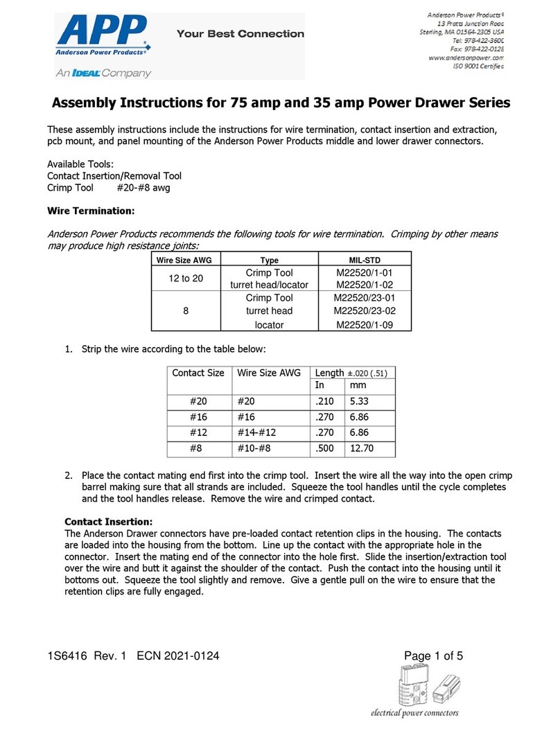
1. Wire Preparation - Strip cable to dimensions shown in Table D.
Table D: Cable Stripping Dimensions
"X"
Connector Series Contact Type Inches mm NOTE
SBS
®
75G Power/Ground 0.56 14.0 -
SBS
®
50 Power 0.56 14.0 -
SBS
®
75X
Power 0.56 14.0 -
Aux Pin 0.18 4.6 For use when wire insulation OD is SMALLER than crimp barrel ID
Aux Socket 0.21 5.3
Aux Pin 0.24 6.1 For use when wire insulation OD is LARGER than crimp barrel ID
Aux Socket 0.28 7.1
NOTES: For SBS
®
75X - if using bundled cable, strip outer jacket to 2.05 inches (52mm). Cut power conductor 0.733 inches (18.62mm) shorter than
socket signal conductors. Cut pin signal conductors 0.51 inches (12.95mm) shorter than socket signal conductors.
Contact Part
Number Wire Size Crimp Tool Insertion
Tool Extraction
Tool Inspection
Tool
PM16P12C30 #12 AWG Post-Mate Pin, 6.6mm
PM1000G1
(hand tool &
locator)
TM0001 +
TL0001
Pin + TL0002
Sockets (Mil
Standard hand
tool & locator)
TP0001 +TL0001
(pneumatic tool &
locator)
11038G3 PM1003G1 PM1003GX
PM16P12A30 #12 AWG Pre-Mate Pin, 9.3mm
PM16P12B30 #12 AWG Pre-Mate Pin, 8.5mm
PM16P12S30 #12 AWG Standard Length Pin, 7.7mm
PM16S12S32 #12 AWG Socket
PM16P1416C30 #16 - 14 AWG Post-Mate Pin, 6.6mm
PM16P1416B30 #16 - 14 AWG Pre-Mate Pin, 8.5mm
PM16P1416A30 #16 - 14 AWG Pre-Mate Pin, 9.3mm
PM16P1416S30 #16 - 14 AWG Standard Length Pin, 7.7mm
PM16S1416S32 #16 - 14 AWG Socket
PM16P1620C30 #20 - 16 AWG Post-Mate Pin, 6.6mm
PM1002G1 PM1003G1 PM1003GX
PM16P1620B30 #20 - 16 AWG Pre-Mate Pin, 8.5mm
PM16P1620A30 #20 - 16 AWG Pre-Mate Pin, 9.3mm
PM16P1620S30 #20 - 16 AWG Standard Length Pin, 7.7mm
PM16S1620S32 #20 - 16 AWG Socket
PM16P2024C30 #24 - 20 AWG Post-Mate Pin, 6.6mm
PM16P2024B30 #24 - 20 AWG Pre-Mate Pin, 8.5mm
PM16P2024A30 #24 - 20 AWG Pre-Mate Pin, 9.3mm
PM16P2024S30 #24 - 20 AWG Standard Length Pin, 7.7mm
PM16S2024S32 #24 - 20 AWG Socket

2. Crimp or Solder Contact to Cable Following Recommended Techniques
a. Crimp power and ground contacts using 1309G4 hand tool or 1387G1 pneumatic tool (with appropriate die and locator, as noted in
Tables A and B), following all crimp tool instructions.
b. Crimp auxiliary contacts using PM1000G1 hand tool, TM0001 Mil standard hand tool or TP0001 pneumatic tool (with appropriate
locator, as noted in Table C), following all crimp tool instructions.
c. Soldering is recommended for cables with solid or minimal conductor stranding, ex. THHN type wire. Use rosin flux solder only.
Wrap cable strands. Melt solder into well, heat and insert stripped cable. Continue heating well until solder flows into wire, being
careful not to overflow onto contact surface. Do not solder-dip contacts. Cable clamps are required for solder connections (per
Underwriter’s Laboratories, Inc.), refer to Table E.
NOTES:
1. Follow all crimp tool instructions. Contact APP®Technical Support 978-422-3642 if instructions are missing or for further assistance.
2. SBS®75X: If using the cable clamp, secure the main clamp housing to the SBS®75X connector housing using the included screw and nut
before installing/inserting power and auxiliary contacts (Recommended torque is 8 inches - lbs). If using bundle wires, make sure bundle is
secured (not individual wires).
Table E: Cable Clamp Catalog Numbers
Connector Series Clamp Number Discrete Wire Bundled
SBS®50 990 #8 - 6 AWG (10mm2)-
990G1 #12 - 6 AWG (4 - 10mm2) -
5905 - 0.32 - 0.45 in (4.27 - 11.43mm)
SBS®75X PSBS75XCLP1 #12 - 6 AWG (4 - 10mm2) 0.39 - 0.60 in (9.91 - 15.24mm)
PSBS75XCLP2 #12 - 6 AWG (4 - 10mm2) 0.35 - 0.55 in (8.89 - 13.97mm)
3. Insert Contacts into the SBS®Connector Housing
a. Main Power Contacts
1) Observing proper polarity as marked on the housing, insert terminated contact in rear of housing with notched side of tongue next
to spring.
2) Push terminated contact into housing until it snaps over end of spring; tug slightly to make sure contact is locked into place.
b. Ground Contacts (SBS®75G only)
1) Power/Ground contacts are marked with the ground symbol (⏚) and are used in the center location of the SBS®75G housing only.
2) Observing proper polarity as marked on the housing, insert terminated contact in rear of housing with notched side of tongue next
to spring.
3) Push terminated contact into housing until it snaps over end of spring; tug slightly to make sure contact is locked into place.
c. Optional Auxiliary Contacts (SBS®75x only)
1) Insert terminated contacts into the rear side of the connector housing using insertion tool #11038G3 for #12 AWG and #16 - 14
AWG contacts and using insertion tool #PM1002G1 for #20 - 16 AWG and #24 - 20 AWG contacts.
2) Use inspection tool #PM1003GX to ensure the auxiliary contact is properly seated in the connector housing.
3) To remove an auxiliary contact from the connector housing, use the extraction tool #PM1003G1 from the front side of the
connector housing. Contact will release from the rear side of the connector housing.
NOTES:
1) With APP®logo facing up, the two UPPER holes are for PIN contacts, and the two LOWER holes are for SOCKET contacts.
2) Use the recommended auxiliary contact insertion, extraction and inspection tools, as noted in Table C.
3) Do not try to insert or extract the auxiliary contacts without the recommended insertion and extraction tools.
Using the Cable Clamp
1) Secure the auxiliary wires using the included cable tie. Loop the tie through the two slots in
the clamp body so that the tie ratchet is outside the clamp body and tighten until fully snug.
2) Screw the clamp to the main clamp body using the included self-tapping screws once the
power and auxiliary contacts are properly inserted. Screws should be torqued in an even
and opposite manner by alternating between screws through the tensioning process. The
bottom of the clamp should be equidistant on both sides from the clamp body when the
recommended torque value is achieved on both screws.
3) Do not over tighten (Recommended torque is 5 in-lbs). If individual wires are being used,
visually inspect to make sure all wires are secured.
All Data Subject to Change 2019-0122 1S6417 Rev 11
© 2019 Anderson Power Products, Inc. All rights reserved. APP®, A®, Anderson Power Products®, SB®, SBE®, SBO®, SBS®, SBX®, Power Clip®, Power Drawer®, PowerMod®, Saf-D-Grid®, SPEC
Pak®, Powerpole® and the APP Logo are registered trademarks of Anderson Power Products, Inc. Anderson™ is a trademark of Anderson Power Products,
Anderson will use reasonable efforts to include accurate and up-to-date content in the assembly instruction. All product information contained in the instruction sheet including ordering information,
illustrations, specifications, and dimensions, are believed to be reliable as of the date of publishing, but is subject to change without notice. Anderson makes no warranty or representation as to its accuracy.
Content in the instruction sheet may contain technical inaccuracies, typographical errors and may be changed or updated without notice. Anderson may also make improvements and/or changes to the
products and/or to the programs described in the content at any time without notice. Current sales drawings and specifications are available upon request.
HEADQUARTERS: Anderson Power Products®, 13 Pratts Junction Road, Sterling, MA 01564-2305 USA T:978-422-3600 F:978-422-0128 • EUROPE: Anderson Power Products®Ltd., Unit 3, Europa
Court, Europa Boulevard, Westbrook, Warrington, Cheshire, WA5 7TN United Kingdom T: +44 (0) 1925 428390 F: +44 (0) 1925 520203 • ASIA / PACIFIC: IDEAL Anderson Asia Pacific Ltd., Unit 922-
928 Topsail Plaza, 11 On Sum Street, Shatin N.T., Hong Kong T:+(852) 2636 0836 F:+(852) 2635 9036 • CHINA: IDEAL Anderson Technologies (Shenzhen) Ltd., Block A8 Tantou Western Industrial
Park, Songgang Baoan District, Shenzhen, PR. China 518105 T: +(86) 755 2768 2118 F: +(86) 755 2768 2218 • TAIWAN: IDEAL Anderson Asia Pacific Ltd., Taiwan Branch, 4F.-2, No.116, Dadun 20th
St., Situn District, Taichung City 407, Taiwan (R.O.C.) T: +(886) 4 2310 6451 F:+(886) 4 2310 6460 • www.andersonpower.com
Disassembling Unmated SBS®Connector
1) Main Power and ground Contacts: Switch off power.
2) Remove contacts by depressing springs at the front end of the connector with an insulated screwdriver having a 1/8” blade.
3) Pull the contact lightly out of the housing.
4) Optional Aux Contacts: Contacts are released from the front side of the connector using extraction tool PM1003G1 and removed from
the rear.
For more information or assistance, contact Anderson Tech Support at 978-422-3642, email at ustechsupport@andersonpower.com or web
chat at http://www.andersonpower.com.
This manual suits for next models
3
Other IDEAL Cables And Connectors manuals

IDEAL
IDEAL 52 User manual

IDEAL
IDEAL APP PM1000G1 User manual

IDEAL
IDEAL APP SBE 320 User manual

IDEAL
IDEAL APP 2300GX Series User manual

IDEAL
IDEAL APP SBE 80 Series User manual

IDEAL
IDEAL APP SPEC Pak User manual

IDEAL
IDEAL FiberTEK III User manual

IDEAL
IDEAL APP SBS User manual

IDEAL
IDEAL APP SBE Series User manual

IDEAL
IDEAL APP Power Drawer User manual
Popular Cables And Connectors manuals by other brands

BTSX
BTSX BIT-MSE-8K-309HD manual

Gleason Reel
Gleason Reel Direct Drive Hazardous Duty Electric Cable Reels... Installation and maintenance instructions

Tapkey
Tapkey Smart Reader manual

Cairn
Cairn OptoSplit II Troubleshooting

Duronic
Duronic ST8B quick start guide

Eaton
Eaton 200 A 15 kV class installation instructions