iDirect Evolution X7 Installation instructions

Installation, Support, and
Maintenance Guide
Evolution X7 Satellite Router
Router Products
September 30, 2013
Evolution X7 Satellite Router Installation, Support, and Maintenance
Guide

ii Installation, Support, and Maintenance Guide
Evolution X7 Satellite Router
Copyright © 2013 VT iDirect, Inc. All rights reserved. Reproduction in whole or in part without permission is
prohibited. Information contained herein is subject to change without notice. The specifications and information
regarding the products in this document are subject to change without notice. All statements, information, and
recommendations in this document are believed to be accurate, but are presented without warranty of any kind,
express, or implied. Users must take full responsibility for their application of any products. Trademarks, brand
names and products mentioned in this document are the property of their respective owners. All such references
are used strictly in an editorial fashion with no intent to convey any affiliation with the name or the product's
rightful owner.
Document Name: ISM_X7_REVA_09302013.pdf
Document Part Number: T0000464

Installation, Support, and Maintenance Guide iii
Evolution X7 Satellite Router
Revision History
The following table shows all revisions for this document. To determine if this is the latest
revision, check the TAC Web site at http://tac.idirect.net.
Revision Date Updates
A September 30, 2013 Initial release (JS)

iv Installation, Support, and Maintenance Guide
Evolution X7 Satellite Router
Revision History

Installation, Support, and Maintenance Guide v
Evolution X7 Satellite Router
Contents
About . . . . . . . . . . . . . . . . . . . . . . . . . . . . . . . . . . . . . . . . . . . . . . . . . . . . . . . xi
Intended Audience . . . . . . . . . . . . . . . . . . . . . . . . . . . . . . . . . . . . . . . . . . . . . xi
Manual Contents. . . . . . . . . . . . . . . . . . . . . . . . . . . . . . . . . . . . . . . . . . . . . . . xi
Document Conventions . . . . . . . . . . . . . . . . . . . . . . . . . . . . . . . . . . . . . . . . . . xii
Related Documents . . . . . . . . . . . . . . . . . . . . . . . . . . . . . . . . . . . . . . . . . . . . . xii
Related Training Services . . . . . . . . . . . . . . . . . . . . . . . . . . . . . . . . . . . . . . . xiii
Getting Help . . . . . . . . . . . . . . . . . . . . . . . . . . . . . . . . . . . . . . . . . . . . . . . . xiii
Warranty, RoHS, WEEE, Declaration of Conformity . . . . . . . . . . . . . . . . . . . . . . xiii
1 Introduction . . . . . . . . . . . . . . . . . . . . . . . . . . . . . . . . . . . . . . . . . . . . . . . . .1
1.1 Features . . . . . . . . . . . . . . . . . . . . . . . . . . . . . . . . . . . . . . . . . . . . . . . . . .1
1.2 Power Supply Options . . . . . . . . . . . . . . . . . . . . . . . . . . . . . . . . . . . . . . . . .2
2 Specifications. . . . . . . . . . . . . . . . . . . . . . . . . . . . . . . . . . . . . . . . . . . . . . . .3
2.1 Mechanical and Environmental Specifications . . . . . . . . . . . . . . . . . . . . . . . . .3
2.2 Power Specifications . . . . . . . . . . . . . . . . . . . . . . . . . . . . . . . . . . . . . . . . . .4
2.3 RF Specifications. . . . . . . . . . . . . . . . . . . . . . . . . . . . . . . . . . . . . . . . . . . . .5
3 Interfaces . . . . . . . . . . . . . . . . . . . . . . . . . . . . . . . . . . . . . . . . . . . . . . . . . . .7
3.1 X7 Router Front LEDs. . . . . . . . . . . . . . . . . . . . . . . . . . . . . . . . . . . . . . . . . .8
3.2 X7 Front Panel LED Status Descriptions . . . . . . . . . . . . . . . . . . . . . . . . . . . . .8
3.3 X7 Router Rear Panel Description . . . . . . . . . . . . . . . . . . . . . . . . . . . . . . . . 10
4 X7 Router Installation. . . . . . . . . . . . . . . . . . . . . . . . . . . . . . . . . . . . . . . . 13
4.1 Installation Steps at a Glance . . . . . . . . . . . . . . . . . . . . . . . . . . . . . . . . . . . 13

vi Installation, Support, and Maintenance Guide
Evolution X7 Satellite Router
Contents
4.1.1 Pre-Installation Guidelines . . . . . . . . . . . . . . . . . . . . . . . . . . . . . . . . . . . 13
4.1.2 Installation Checklist . . . . . . . . . . . . . . . . . . . . . . . . . . . . . . . . . . . . . . . 14
4.2 Tools and Supplies Required for Installation . . . . . . . . . . . . . . . . . . . . . . . . . 15
4.3 Unpacking iDirect Evolution X7 Router Equipment. . . . . . . . . . . . . . . . . . . . . 15
4.4 Components Typically Included in an Order . . . . . . . . . . . . . . . . . . . . . . . . . 15
4.5 X7 Router Mounting. . . . . . . . . . . . . . . . . . . . . . . . . . . . . . . . . . . . . . . . . . 16
4.5.1 Installing With an AC Power Supply (Option 1 or 2) . . . . . . . . . . . . . . . . . . . . 16
4.5.2 Installing With a 24-48 VDC Power Supply (Option 3) . . . . . . . . . . . . . . . . . . . 17
4.6 Preparing the PC for Connection to the X7 Router . . . . . . . . . . . . . . . . . . . . . 18
4.7 Web Interface LED Status Indicators . . . . . . . . . . . . . . . . . . . . . . . . . . . . . .18
4.8 Configuring the X7 Router . . . . . . . . . . . . . . . . . . . . . . . . . . . . . . . . . . . . . 18
5 Maintenance. . . . . . . . . . . . . . . . . . . . . . . . . . . . . . . . . . . . . . . . . . . . . . . . 19
5.1 Safety Guidelines to Observe During Servicing . . . . . . . . . . . . . . . . . . . . . . . 19
5.1.1 Servicing . . . . . . . . . . . . . . . . . . . . . . . . . . . . . . . . . . . . . . . . . . . . . . 19
5.1.2 Conditions Requiring Service . . . . . . . . . . . . . . . . . . . . . . . . . . . . . . . . . . 19
5.2 Maintaining the X7 Router . . . . . . . . . . . . . . . . . . . . . . . . . . . . . . . . . . . . . 20
5.2.1 Temperature Control. . . . . . . . . . . . . . . . . . . . . . . . . . . . . . . . . . . . . . . 20
5.2.2 90 day maintenance . . . . . . . . . . . . . . . . . . . . . . . . . . . . . . . . . . . . . . . 20
5.3 Troubleshooting the X7 Router . . . . . . . . . . . . . . . . . . . . . . . . . . . . . . . . . .20
5.4 Removing and Replacing the Power Module . . . . . . . . . . . . . . . . . . . . . . . . . 21
5.5 Repacking the X7 Router . . . . . . . . . . . . . . . . . . . . . . . . . . . . . . . . . . . . . . 22
Appendix A Acronyms and Abbreviations . . . . . . . . . . . . . . . . . . . . . . . . 23
Appendix B Safety . . . . . . . . . . . . . . . . . . . . . . . . . . . . . . . . . . . . . . . . . . . . 27
B.1 Installation Guidelines . . . . . . . . . . . . . . . . . . . . . . . . . . . . . . . . . . . . . . . . 27
B.2 Electrical Safety . . . . . . . . . . . . . . . . . . . . . . . . . . . . . . . . . . . . . . . . . . . . 28
B.3 Physical and Environmental Considerations . . . . . . . . . . . . . . . . . . . . . . . . . 29
Appendix C Tools Needed . . . . . . . . . . . . . . . . . . . . . . . . . . . . . . . . . . . . . . 31
Appendix D Cable Preparation . . . . . . . . . . . . . . . . . . . . . . . . . . . . . . . . . . 33
D.1 Coax Cable Preparation . . . . . . . . . . . . . . . . . . . . . . . . . . . . . . . . . . . . . . . 33
D.2 Ethernet Port Pinouts . . . . . . . . . . . . . . . . . . . . . . . . . . . . . . . . . . . . . . . . 37

Installation, Support, and Maintenance Guide vii
Evolution X7 Satellite Router
Contents
D.2.1 Ethernet Port Pinouts . . . . . . . . . . . . . . . . . . . . . . . . . . . . . . . . . . . . . . 37
D.2.2 Straight Through and Crossover RJ-45 Cables . . . . . . . . . . . . . . . . . . . . . . . 38
D.3 Console Port Connection . . . . . . . . . . . . . . . . . . . . . . . . . . . . . . . . . . . . . . 38
Appendix E DC Power Supply Installation. . . . . . . . . . . . . . . . . . . . . . . . . 41
Appendix F X7 Reset . . . . . . . . . . . . . . . . . . . . . . . . . . . . . . . . . . . . . . . . . . 45
F.1 Level 0 Reset . . . . . . . . . . . . . . . . . . . . . . . . . . . . . . . . . . . . . . . . . . . . . . 45
F.2 Level 1 Reset . . . . . . . . . . . . . . . . . . . . . . . . . . . . . . . . . . . . . . . . . . . . . . 45
F.3 Level 2 Reset . . . . . . . . . . . . . . . . . . . . . . . . . . . . . . . . . . . . . . . . . . . . . . 46

Installation, Support, and Maintenance Guide viii
Evolution X7 Satellite Router
Figures
Figure 1-1. X7 Router . . . . . . . . . . . . . . . . . . . . . . . . . . . . . . . . . . . . . . . . . . . . . . . . . 1
Figure 3-1. X7 Router Front Panel LED Display. . . . . . . . . . . . . . . . . . . . . . . . . . . . . . . . . 8
Figure 3-2. Rear Panel Description . . . . . . . . . . . . . . . . . . . . . . . . . . . . . . . . . . . . . . . 10
Figure C-1. Recommended Installation Tools. . . . . . . . . . . . . . . . . . . . . . . . . . . . . . . . . 31
Figure D-1. Coax Cable Cutting Technique . . . . . . . . . . . . . . . . . . . . . . . . . . . . . . . . . . 34
Figure D-2. Cutting Technique for Removing Foil in the Braid. . . . . . . . . . . . . . . . . . . . . . 35
Figure D-3. Folding the Braid . . . . . . . . . . . . . . . . . . . . . . . . . . . . . . . . . . . . . . . . . . . 35
Figure D-4. Attaching the Compression fitting F-type Connector . . . . . . . . . . . . . . . . . . . . 36
Figure D-5. Compression fitting F-Type Weatherproof Plug and Tool . . . . . . . . . . . . . . . . . 36
Figure D-6. RJ-45 Cable Connectors: Receptacle and Plug . . . . . . . . . . . . . . . . . . . . . . . . 38
Figure D-7. Holding the RJ-45 Cable Connectors . . . . . . . . . . . . . . . . . . . . . . . . . . . . . . 38
Figure D-8. RJ-45 to DB-9 Female DTE Adapter . . . . . . . . . . . . . . . . . . . . . . . . . . . . . . . 40
Figure E-1. DC-DC Power Supply Assembly at a Glance . . . . . . . . . . . . . . . . . . . . . . . . . . 42

Installation, Support, and Maintenance Guide ix
Evolution X7 Satellite Router
Tables
Table 2-1. Mechanical and Environmental Specifications............................................... 3
Table 2-2. Power Specifications ............................................................................ 4
Table 2-3. RF Specifications ................................................................................. 5
Table 3-1. X7 Router Front Panel Description ............................................................ 8
Table 3-2. X7 Router iDX 3.2 LED Descriptions ........................................................... 9
Table 3-3. X7 Router Rear Panel Connector and LED Descriptions ................................... 11
Table 5-1. Troubleshooting Events and Actions to Take ............................................... 20
Table 5-2. Removing and/or Replacing the Power Module ............................................ 22
Table C-1. Recommended Installation Tools and Equipment.......................................... 31
Table D-1. Coax Trim Dimensions.......................................................................... 34
Table D-2. Ethernet Port Pinouts .......................................................................... 37
Table D-3. RJ-45 to DB-9 Pinouts .......................................................................... 39
Table E-1. X7 Router DC Power Module Connector Parts .............................................. 41
Table E-2. Power Module Power Cable Installation Instructions Detail.............................. 42

x Installation, Support, and Maintenance Guide
Evolution X7 Satellite Router
Tables

Installation, Support, and Maintenance Guide xi
Evolution X7 Satellite Router
About
This manual provides important safety information and explains how to install and maintain
the iDirect Evolution X7 Satellite Router
This chapter contains the following sections:
•Intended Audience
•Manual Contents
•Document Conventions
•Related Documents
•Related Training Services
•Getting Help
•Warranty, RoHS, WEEE, Declaration of Conformity
Intended Audience
This manual is intended for use by the VSAT (Very Small Aperture Terminal) equipment
installer, System Engineer, and Network Operator responsible for maintaining the iDirect
Network. Only qualified service personnel should install the X7 Router. Familiarity with
cabling and wiring practices is beneficial.
Manual Contents
In addition to the information in this chapter, this manual also includes the following:
•Chapter 1, Introduction on page 1, provides an overview and description of the X7 Router
•Chapter 2, Specifications on page 3 describes the mechanical, environmental and RF
specifications of the X7 Router
•Chapter 3, Interfaces on page 7 provides connector descriptions of the X7 Router
•Chapter 4, X7 Router Installation on page 13 describes procedures for installing the
X7 Router
•Chapter 5, Maintenance on page 19 describes maintenance procedures for the X7 Router
NOTE: A basic list of acronyms and abbreviations can be found in Appendix A,
Acronyms and Abbreviations.

xii Installation, Support, and Maintenance Guide
Evolution X7 Satellite Router
About
Document Conventions
This section illustrates and describes the conventions used throughout this document.
cd /etc/snmp/
WARNING: A Warning highlights an essential operating or maintenance
procedure, practice, condition, or statement which, if not strictly observed,
could result in injury, death, or long term health hazards.
CAUTION: A Caution highlights an essential operating or maintenance procedure,
practice, condition, or statement which, if not strictly observed, could result in
damage to, or destruction of, equipment or a condition that adversely affects
system operation.
NOTE: A Note is a statement or other notification that adds, emphasizes, or
clarifies essential information of special importance or interest.
Related Documents
The following documents are available at http://tac.idirect.net. Consult these documents for
information about installing and using iDirect’s satellite network software and equipment.
• iDX iBuilder User Guide
• iDX iMonitor User Guide
• Web iSite User Guide
• iDX Satellite Router Installation and Commissioning Guide
Convention Description Example
Command Used when the user is required to
enter a command at a command
line prompt or in a console.
Enter the command:
Terminal
Output
Used when showing resulting
output from a command that was
entered at a command line or on a
console.
crc report all
8350.3235 : DATA CRC [ 1]
8350.3502 : DATA CRC [5818]
8350.4382 : DATA CRC [ 20]
Screen
Reference
Used when referring to text that
appears on the screen on a
Graphical User Interface (GUI).
Used when specifying names of
commands, menus, folders, tabs,
dialogs, list boxes, and options.
1. To add a remote to an inroute group, right-click
the Inroute Group and select Add Remote.
The Remote dialog box has a number of user-
selectable tabs across the top. The Information
tab is visible when the dialog box opens.
Hyperlink Used to show all hyperlinked text
within a document or external
links such as web page URLs.
For instructions on adding a line card to the
network tree, see Adding a Line Card on
page 108.

Installation, Support, and Maintenance Guide xiii
Evolution X7 Satellite Router
About
• iDX Release Notes
• iDX Technical Reference Guide
• Quick Start Guide (QSG), included in package with router
Related Training Services
iDirect offers scheduled classroom training at various global training centers, as well as
eLearning, in the installation, operation, maintenance and management of iDirect satellite
networks. For training course descriptions and available training dates visit the iDirect web
site Training and Services at: http://www.idirect.net/Training-and-Services.aspx or call +1
(800) 648-8240 for class registration and information.
Getting Help
iDX Software users guides, installation procedures and guides, an FAQ page, and other
documentation that supports iDirect products, are available on the TAC Web site located at:
http://tac.idirect.net.
To find answers to questions or information, contact the iDirect Technical Assistance Center
(TAC) at (703) 648-8151.
iDirect strives to produce documentation that is technically accurate, easy to use, and helpful
Warranty, RoHS, WEEE, Declaration of Conformity
Complete iDirect hardware product statements for the X7 Router are available at these Web
sites:
•http://www.idirect.net/warranty, for the hardware warranty
•http://www.idirect.net/rohs, for the RoHS statement of compliance
•http://www.idirect.net/weee, for the WEEE statement of compliance
•http://www.idirect.net/doc, for the Declaration of Conformity

xiv Installation, Support, and Maintenance Guide
Evolution X7 Satellite Router
About

Installation, Support, and Maintenance Guide 1
Evolution X7 Satellite Router
1 Introduction
The iDirect Evolution X7 Satellite Router (X7 Router) is a next-generation router supporting
DVB-S2/ACM on the outbound and A-TDMA. It uses a compact, rack-mount design, embedded
8-port switch, and variant power supply configurations making it an ideal enterprise class
solution. In addition to Web iSite support, the availability of a Downstream Configuration
template and multi-image support on the X7 Router enables simple deployments and seamless
upgrades.
This chapter contains the following sections:
• Section 1.1, Features on page 1
• Section 1.2, Power Supply Options on page 2
This manual explains how to safely install and maintain the X7 Router, and it includes
important safety information in Appendix B, Safety.
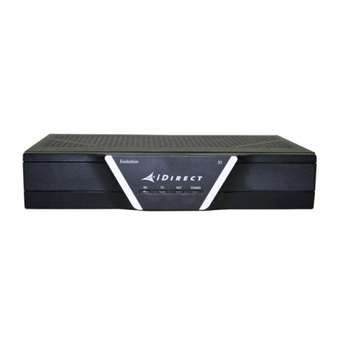
The Evolution X7 Satellite Router is shown in Figure 1-1.
Figure 1-1. X7 Router
1.1 Features
Highlights:
• Increased throughput capabilities
• 1 RU high router chassis fitting in standard telecom racks
• Variant power supply module configurations
• Dual image support and Web iSite for ease of deployment and upgrades
• Communications-on-the-Move (COTM) support
• AES Encryption

2 Installation, Support, and Maintenance Guide
Evolution X7 Satellite Router
Power Supply Options
1.2 Power Supply Options
The X7 Router is available with these power supply configurations:
• Option 1: 100-240V AC +24V Power Supply (Standard)
Option 1 power supply for the X7 Router is standard with a single +24V power support for
the X7’s BUC.
• Option 2: 100-240V AC +24 V, +48 V Power Supply
Option 2 AC power module for the X7 Router comes with dual selectable +24V/+48V
power support for either a +24V or +48V BUC.
• Option 3: 36-76V DC +24 V, +48 V Power Supply
Option 3 DC power module for the X7 Router comes with dual selectable +24V/+48V
power support for either a +24V or +48V BUC.

Installation, Support, and Maintenance Guide 3
Evolution X7 Satellite Router
2 Specifications
This chapter describes the mechanical, environmental, power, and RF specifications for the
X7 Router.
This chapter contains the following sections:
• Section 2.1, Mechanical and Environmental Specifications on page 3
• Section 2.2, Power Specifications on page 4
• Section 2.3, RF Specifications on page 5
2.1 Mechanical and Environmental Specifications
The installation site must be able to accommodate the X7 Router mechanical and
environmental specifications. The mechanical and environmental specifications are listed in
Table 2-1.
Table 2-1. Mechanical and Environmental Specifications
Category Description
Dimensions 17.5 in (44.5 cm) W x 12” in (30.5 cm) D x 1.75 in (4.45 cm) H
19-inch (48.26 cm) rack mountable, 1 RU (1.75 inches (44.45 mm))
Weight 10 lbs (4.55 kg)
Heat Dissipation < 375 Watts
Airflow Front Panel Fan Assist (2 fans), Power Supply (1 fan), Rear Exhaust,
No Filter
Ambient Temperature
Operational
Storage
32˚to +122˚F (0˚to +50˚C) @ Sea Level
32˚to +113˚F (0˚to +45˚C ) @ 10,000 Feet
-40˚to +176˚F (-40˚to 80˚C)
Temperature Gradient .5˚C per minute ( but < 20˚C per hour)
Relative Humidity
Operational
Storage
90%, non-condensing
5 to 93%

4 Installation, Support, and Maintenance Guide
Evolution X7 Satellite Router
Power Specifications
2.2 Power Specifications
The X7 Router power specifications are listed in Table 2-2.
CAUTION: If negative voltages are used such as Telecom -48VDC, the negative
most voltage is always connected to –ve terminal (in the Telecom case this
would be -48V) and the positive most voltage is always connected to the +ve
terminal (in the Telecom case this would be 0VR). Chassis can be referenced
to +ve, -ve or left floating (i.e. not connected to either +ve or –ve) as
required as the power module is fully isolated input to the chassis.
Altitude
Operational
Survival
< 10,000 ft
< 35,000 ft
Shock
Operational
Survival
< 20G
< 40G (ISTA-1A)
Vibration
Operational
Survival
0.21 Grms @ 500 Hz
2.09 Grms @ 500 Hz
Table 2-1. Mechanical and Environmental Specifications (continued)
Category Description
Table 2-2. Power Specifications
Category Description
Input Voltage Range Option 1: 100-240 VAC, Auto-Ranging
Option 2: 100-240 VAC, Auto-Ranging
Option 3: 36-76 VDC
Frequency Options 1 & 2: 50-60 Hz, Auto-Ranging
AC Power Consumption ption 1: 2.7 A , 270 W
Option 2: 3.4 A , 340 W
DC Power Consumption Option 3: 8.3 A , 310 W
BUC Voltage Option 1: 24 VDC
Option 2 & 3: Selectable, 24 or 48 VDC
DC Power @ TX Output Option 1, 2, & 3: 24 VDC @ 4.9A (117 W MAX)
Option 2 & 3: 48 VDC @ 3.3A (158 W MAX)
DC Power @ RX Inputs 13-18 VDC @ 500 mA, voltage is software configurable

Installation, Support, and Maintenance Guide 5
Evolution X7 Satellite Router
RF Specifications
2.3 RF Specifications
The Evolution X7 Satellite Router RF specifications are listed in Table 2-3.
Protection Over-Voltage Protection for LNB and BUC DC
Over-Current Limiting for LNB and BUC DC
Options 1 & 2: Primary AC fuse within PS module (250 VAC, T6.3 A)
Option 3: Primary DC fuse within PS module (250 V, 16 A)
AC Input Connector IEC-60320-C14, 3-cond, Male
AC Power Cord Supplied, per country of use
DC Input Connector Self-capturing terminal block, 14-16 AWG
Efficiency 87% Min
Table 2-2. Power Specifications (continued)
Category Description
Table 2-3. RF Specifications
Category Description
IF Interface, Impedance Type “F”, Zo = 75 ohms
Frequency Range
Transmit
Receive
950 - 1950 MHz
950 - 2150 MHz
Tuning Step Size
Transmit
Receive
10 Hz
55 KHz
RF Power
Transmit
Receive, Minimum
Receive, Maximum
Frequency Phase Noise
1 KHz -75
10 KHz -85
100 KHz -95
1 MHz -105
-35 to +5 dBm, 0.5 dB step
-130 + 10Log(Sym rate) dBm (Single carrier)
-5 dBm (Wideband Composite)
Tx SSB Phase Noise
LNB Support Fsym > 10 Msps: DRO LNB
Fsym < 10 Msps: PLL LNB (internal reference)
Fsym > 1 Msps: Universal LNB w/22 KHz tone
Receiver Noise Figure 15 dB

6 Installation, Support, and Maintenance Guide
Evolution X7 Satellite Router
RF Specifications
Transmit Carrier Suppression < -40 dBc
Spurious & Harmonic Content < -60 dBc, with output @ -20 dBm, (In-band < -32 dBc)
Transmitter Muting 50 dB (min); residual carrier < -90 dBm with baseband (BB) and
RF muted
Table 2-3. RF Specifications (continued)
Category Description
Table of contents
Other iDirect Network Router manuals
iDirect
iDirect Evolution 8000 Series User guide
iDirect
iDirect Evolution X1 User guide
iDirect
iDirect iQ Desktop+ Installation instructions
iDirect
iDirect Evolution X3 User guide
iDirect
iDirect iNFINITI 3000 User manual

iDirect
iDirect iQ 200 Installation instructions
iDirect
iDirect iQ LTE Series Installation instructions
iDirect
iDirect evolution x5 User manual
iDirect
iDirect Evolution X1 User manual
iDirect
iDirect Evolution X1 Installation instructions
