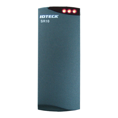
IDTECK SR10RW User manual

User’s Manual
13.56MHz [MIFARE]
Contactless Smart Card Reader / Writer

2
Table of Contents
1. Important Safety Instructions ...................................................... 3
2. General................................................................................... 4
3. Features.................................................................................. 4
4. Specification............................................................................ 5
5. Identifying Supplied Parts........................................................... 5
6. Installation .............................................................................. 6
7. Color Coded & Wiring Table ........................................................ 8
8. Output Format.......................................................................... 9
9. Wire Connection to Access Controller ......................................... 11
10. Operation ............................................................................ 12
11. Troubleshooting .................................................................... 14
12. FCC Registration Information................................................... 15
13. Warranty Policy and Limitation of Liability .................................. 16
14. How to Make RMA Request (After Sales Service).......................... 17

3
1. Important Safety Instructions
The description below is to keep user’s safety and prevent any product damage. Please full
y read these instructions and use the product properly.
Danger: This symbol indicates that incorrect handling of the product may resu
lt in serious injury or death.
Warning: This symbol indicates that incorrect handling of the product may res
ult in injury or property damage.
- Only use the standard voltage (DC +12V / 350mA).
- If the product emits smoke or smells, stop using the product. Unplug the product from DC power source
and contact nearest service center.
- Do not install the product in a place subject to humidity, dust (metallic dust) or splashing water
(raindrops).
- Do not install the product in a place not meeting the operating humidity and temperature specified in the
specification.
- Do not install the product with tools such as driver in hand when power is being supplied.
- Do not drop liquid onto the product such as water and give the product a severe shock.
- Do not place magnetic objects near the product.
- Do not replace the wiring cables installed by experts.
- Do not use the product under direct sunlight or in a heat-producing place such as a place near a heating
apparatuses.
- If you want to relocate the installed product, turn power off and then move and reinstall it.
- Do not use flammable sprays or objects near the product.
- Do not let anyone but the manger touch the product except using it for normal purpose.
- If liquid has been spilled on the product, unplug it first.
- Do not clean the product with water. Clean gently with dry cloth or towel.
- Do not use chemicals such as benzene, thinner or acetone for cleaning.
CAUTIONS ABOUT INSTALLATION
CAUTIONS ABOUT POWER
CAUTIONS ABOUT USAGE
CAUTIONS ABOUT CLEANING

4
2. General
The IDTECK SR10RW Smart Card Reader / Writer can be compatible with Philips Mifare™ Card.
The unit provides integrated operation of reader and writer and is designed by which can install easily to
door frame or wall.
The IDTECK SR10RW is elegant looking and built in an attractive 10cm (4") read range smart card reader.
It also reads serial numbers from Philips Mifare™ Cards compatible, and can read and write special data
of memory field internal card when operating of the unit is set by PRG2000RW.
The IDTECK SR10RW can support communication between PRG2000RW, PC and third party controller
using methods of RS232 and RS485.
Three LED indicators of red and green, inside Piezo buzzer sound will guarantee you accurate and reliable
system operations.
3. Features
- 13.56MHz [MIFARE] Contactless smart Card Reader / Writer
- Read Range: Up to 4 inch (10cm)
- Read the Card which is issued by PRG2000RW (Smart Card Read / Write Programmer)
- RS232 / RS485 (default), 26 / 34bit Wiegand (selectable) Output Format
- 3 Array LED Indicators (Red and Green) and Buzzer
- External LED Control
- External Buzzer Control
- Easy to install on Mullion Mounting
- Solid Epoxy Potted
- Waterproof / IP65 / IP66
- Reverse Polarity Protection
- Compatible Software: Smart Card Read / Write Software
- Compatible Controller:
(26bit Wiegand) iCON100, iTDC, iMDC, Third Party Controller
(34bit Wiegand) iCON100SR, iTDC-SR, iMDC, Third Party Controller

5
4. Specification
Model
SR10RW
CPU
8bit Microprocessor
Frequency
13.56MHz [MIFARE]
Read Range
ISK50 / IHC80 / IMC135: Up to 2 inches (5cm),
ISC80: Up to 4 inches (10cm)
Reading Time
30ms
Power / Current
DC12V / Max.150mA
Read Range
ISK50/IMC135 : 2 inches (5cm)
ISC80 : 4 inches (10cm)
Output Format
RS232 / RS485 (Default), 26 / 34bit Wiegand (Selectable)
LED Indicator
3 Array LED Indicators (Red, Green)
Beeper
Piezo Buzzer
Operating Temperature
-35to +65C ( -31F to +149F )
Operating Humidity
10% to 90% relative humidity non-condensing
Color
Dark Pearl Gray
Material
Polycarbonate
Dimension (W x H x T)
1.8" X 4.5" X 0.88" (47mm X 115mm X 22mm)
Weight
120g (0.26lb)
Certification
FCC, CE, KCC, RoHS
5. Identifying Supplied Parts
Please unpack and check the contents of the box.
Reader Module
SR10RW Bezel
User’s Manual
Anchor Bolt
3.5*40 screw
3.5*25 screw
Magnet
(1ea)
(1ea)
(1copy)
(2ea)
(2ea)
(2ea)
(1ea)

6
6. Installation
6-1. Mullion/Wall Mount:
Drill 6-32 or M3 screws hole at 3.3" (8.38cm) intervals vertically
And drill one 1/2" hole between previously drilled two holes for the reader cable 1.7" apart from the
top hole.
(If the gang box is already installed on the wall then skip this step.)
6-2. Fixing a Tamper Magnet to the wall
Attach a tamper magnet with tools such as double-sided tape on the left of the bottom hole that you
drilled in 6-1. (Refer to the figure below)
6-3. Fixing Reader Module
Put reader cable into the center hole and fix the reader module using two 6-32 or M3 screws.
6-4. Putting on the Cover
Put on cover into the reader module, and then push it until hearing the locking sound.

7
6-5. Cautions during Installation
6-5-1. When installing SR10RW on metal Frame
Read range will be reduced if located on metal surfaces or in the vicinity of metal objects. The
amount of reduction will be a factor of the amount of metal and the distance the Reader is from
the metal. Metal near the Reader absorbs energy from the Reader excite field and affects the
signal being received from the card by re-directing excite field transmissions into the receiver
circuitry. Moving the Reader away from the metal objects reduces energy loss.
Try to limit the amount of metallic materials installed near the SR10RW.
Use a plastic electrical box if possible.
When installing the Reader on metal door frame, add Isolation Spacers between the Reader and
metal door frame. If you do so, read range reduction can be improved.
The typical read distance specification (2-4 inches at 12VDC) refers to operation without metal in
the vicinity of the Reader.
The read distance will be reduced if metal is installed nearby. The SR10RW generate a magnetic
field on all sides of the Reader. Any metal that conducts electricity, especially metal that contains
iron, steel or copper will interfere with the field and reduce the effective spacer between the
Reader and the metal object.
6.5.2. When installing two readers side by side or back to back
Read range is not affected if the side by side distance between two readers is equal to
or greater than eight inches (20cm). If the distance between the two readers is less than
eight inches (20cm), field interference between the two readers may result in a double-
badge read.
When installing two readers back-to-back on a wall that will separate the two readers by
Two readers can simultaneously read the same badge or tag if the distance
between the two readers is less than 8 inches (20cm), side by side.
Note

8
eight inches (20cm) or less, a metal plate (for example: Reader isolation plate, metal wall)
must be placed between the readers. To obtain the maximum read range, mount each
proximity reader onto one or more Isolation Spacers.
7. Color Coded & Wiring Table
Signal
Color
Main Power (+12V)
Red
Power Ground (GND)
Black
ABA Track II CP Out
Orange
Wiegand Data 0 Out / ABA Track II Data Out
Green
Wiegand Data 1 Out / ABA Track II Clock Out
White
Buzzer Control In
Blue
LED Control In
Yellow
Tamper Switch Out
Gray
RS232 (TX)
Purple
RS232 (RX)
Brown
RS485 (A)
Pink
RS485 (B)
Cyan
* Cut out the tail connector before installation.
Two readers can simultaneously read the same badge or tag if the distance
between the two readers is less than 8 inches (20cm), back-to-back.
Note

9
8. Output Format
8-1. 26/34bit Wiegand output format
1. Data format
26bit Wiegand output format
34bit Wiegand output format
Bit 1
Even parity of bit 2 ~ bit 13
Bit 1
Even parity of bit 2 ~ bit 17
Bit 2∼9
Facility code (000 ~ 255)
Bit 2∼25
4byte ID number
(0000000001 ~ 4,294,967,295)
Bit 10∼25
ID number (00000 ~ 65,535)
Bit 26
Odd parity of bit 14 ~ bit 25
Bit 34
Odd parity of bit 18 ~ bit 33
2. Timing diagram
8-2. ABA Track II Magstripe output format
1. Data format (for Card numbers)
3.5V
0.5V
100uS
1mS
Data 0
100uS
100uS
Data 1
3.5V
0.5V
5V
5V
0V
0V
Start Character
(11010 Hex ‘B’)
ID number
(1248P (0000000001~ 4294967295))
low bit first, odd parity last
LRC
Zero bit
Zero bit (10bit)

10
2. Data format (for PIN)
3. Timing diagram
8-3. RS-232 output format
1. Data format (Baud rate: 9600bps)
+15V
-15V
+3V
-3V
Space (=0)
Mark (=1)
8 Data Bits 2 Stop Bits
Indeterminate
Region
Data packet corresponding to ASCII character 'A'
Start Bit
0 1 0 0 0 0 0 1 0
LSB MSB
0V
Start Character
(11010 Hex ‘B’)
PIN (1char to 8char)
low bit first, odd parity last
LRC
Zero bit
Zero bit (10bit)
CLK
(RD1)
Data
(RD0)
1240us
940us
6000us
6000us
CP
1544us

11
9. Wire Connection to Access Controller

12
10. Operation
10-1. After applying a power to the SR10RW, buzzer sounds and 3 LED indicators turn on changing color
red, green and red in order. And then 3 LED indicators turn off. Each LED indictor turns on red from
the left in order again with beeping. (After applying a power, initialization status of the SR10RW is set
to read card serial number when RF card is read.)
10-2. Until turning on green LED indictors with beeping one time, you make card read on the reader. After
the reader transmits card data to access controller, LED indicator return red to wait for next card
reading.
If the reader transmits card data normally, all red LED indicators turn off with beeping one
time and then each LED indicator turns on green from the left in order. If all LED indicators
turn on green, they are changed red.
If not, buzzer sounds twice for retrying and red LED indicators flicker one time at all.
In addition, buzzer sounds three times in the case of error. Also red LED indicators flicker one
time at all.
※If the unit doesn‟t operate normally, refer to „11. Troubleshooting‟on this manual.
10-3. LED Control
You can control the LED of the device at your preference.
Connect the LED Control Input wire (Yellow wire) to the NO port of controller relay output, and GND
to the COM port. Set I/O of the controller; then you can change the color of the LED. While the LED
control is working, the green LED stays on.
This function is used for changing the LED color representing standby from red to green and applied
to make various modifications according to the different I/O setting of the controller.
For more information about the I/O setting of the controller, refer to the controller‟s user manual.
10-4. Buzzer Control
You can control the buzzer of the device at your preference.
Connect the Buzzer Control Input wire (Blue wire) to the NO port of controller relay output, and GND
to the COM port. Set I/O of the controller; then you can generate beep sound. While the buzzer
control is working, the product keeps sounding beep. The controller can use the I/O setting to set the
buzzer controller so that it sounds the additional beep for authorized/unauthorized access. For more
information about the I/O setting of the controller, refer to the controller‟s user manual.
※Caution: If you keep generating beep sound, the reader can’t read the card.
10-5. Tamper Switch
If SR10RW is removed from the wall (or magnet) with the interval of more than 1cm, temper switch is
operated, so 3 LED indicators turn on/off in order and buzzer keep sounding until no.7 of DIP switch
is turned on.
If you want to set not to operate tamper switch, no.7 of DIP switch keep switching on.
10-6. Setting a “Smart Card Read / Write Software”
After applying a power, initialization status of the SR10RW is set to read card serial number.
To set SR10RW as access control, debt meal and cashless payment, refer to user‟s manual of
IDTECK PRG2000RW or Smart Card Read / Write Software.

13
10-7. SR10RW Configuration
The SR10RW is connected to PRG2000RW for access control, debt meal and cashless payment.
To know connection methods, refer to the user‟s manual of PRG2000RW or Smart Card Read / Write
Software.
The SR10RW supports RS232 or RS485 communication on the all field. Their communication is set
by DIP switch. The SR10RW also supports 26/34bit Wiegand output format when it is set for access
control.
10-8. 8 Channel DIP Switch Setting
There is an 8 channel DIP switch and the switch is used to set Board ID, RS232/RS485, Temper
output and Initialization.
Switch Number.
Description
No. 1 - 5
Board ID Setting (See the „Board ID Example‟below)
No. 6
RS232 or RS485 (0: RS232, 1: RS485)
No. 7
Tamper output enable / disable (0: Enable, 1: Disable)
No. 8
Initialization (For initialization, switch on to „1‟position and keep it about 1.5
seconds and then switch down to „0‟position.)
※Board ID Example
The 5 switches (No.1 ~ 5) are used to set board ID. Each switch has assigned address value and
the Board ID is the sum value of each switch set to “1” position. Board ID can be set from „0‟ to „31‟.
Refer to the example below.
(Figure: Address Value)
RW

14
Board ID= 0
Board ID = 2+8 = 10
Board ID = 1+2+4+8+16 = 31
(Figure: Board ID Example)
11. Troubleshooting
※If a problem occurs during the use of the product, do not attempt to disassemble the product by
yourself. Please check the following suggestions. If your problem still persists, contact our customer
service center.
☞Card is not read when user approaches card on Smart Card Read / Write Series.
Cause
At impressed voltage whether use not regular voltage(DC 12V) but irregular voltage
or do different card type
Solution
1. Confirm to regular voltage in manual and catalog
2. Confirm to Phillips Mifare™Card (or not to it.)
=> Never use 125KHz card.
Confirm 13.56MHz card whether ISO14443 B Type or ISO15693.
Never operate ISO14443 B Type and ISO15693 too.
(Contact buying company to confirmation usage of card.)
3. Confirm whether proper format or improper format in corresponding reader.
=> Developed reader for that purpose of access, attendance and debt meal
etc. is two usages. The one is Serial Number and another is to encode
desired data in sector and block
Being the other, confirm to same format of issued card and reader
(Contact card publisher or buying company to confirmation usage.)
4. Don‟t reading despite confirmation from step 1 to step 3, contact RMA center.
☞When sounding buzzer and being on LED faintly at impressed voltage
Cause
At installing reader, whether use adapter(less capacitance adapter than electric
current of reader’s consumption) to power or don’t supply enough current to reader
because length of power cable is too long.
Solution
1. When using adapter, confirm to use more capacitance adapter than mentioned
electric current of reader’s consumption manual and catalog.
If several readers connect one adapter, confirm to use much more capacitance
adapter than reader‟s count by electric current of reader’s consumption value.
2. Although power can supply enough current, replace dedicated line or reinforce
line whether power cable isn‟t dedicated line or power loss is much because
communication cable, UTP cable and etc. are too long.
3. If same situation appears despite confirmation from step1 to step2, contact RMA
center.

15
☞.When card reads, Read Range of every card differ.
Cause
Although same formatted card, specific character of card classified by manufacturing
company differs. (Reader of IDTECK is tuned by standard Phillips Mifare™Card.)
Solution
1. Unique character of coil and manufacturing process by card manufacture
company decide unique card character. So confirm using card to manufacture in
same company. If card made in several kinds of manufacturing company, every
card which comes out Read Range differently is normal operation.
2. If Read Range differs every reading time of card despite same card manufacture
company, contact RMA center.
12. FCC Registration Information
FCC REQUIREMENTS PART 15
Caution: Any changes or modifications in construction of this device which are not expressly approved by
the manufacturer for compliance could void the user's authority to operate the equipment.
NOTE: This device complies with Part 15 of the FCC Rules.
Operation is subject to the following two conditions;
1. This device may not cause harmful interference, and
2. This device must accept any interference received, including interference that may cause undesired
operation.
This equipment has been tested and found to comply with the limits for a Class B Digital Device,
pursuant to Part 15 of the FCC Rules. These limits are designed to this equipment generates, uses, and
can radiate radio frequency energy and, if not installed and used in accordance with the instructions, may
cause harmful interference to radio communications.
However, there is no guarantee that interference will not occur in a particular installation. If this equipment
does cause harmful interference to radio or television reception, which can be determined by turning the
radio or television off and on, the user is encouraged to try to correct interference by one or more of the
following measures.
1. Reorient or relocate the receiving antenna.
2. Increase the separation between the equipment and receiver.
3. Connect the equipment into an outlet on another circuit.
4. Consult the dealer or an experienced radio/TV technician for help.

16
13. Warranty Policy and Limitation of Liability
IDTECK warrants this product against defects in material and workmanship for the product life time under
normal customer use. This Warranty doesn‟t apply: 1) to any product which has been dismantled without
authorization of IDTECK or/and has a damaged or detached QC label on its back side; 2) to any losses,
defects, or damages caused by improper testing, operation, installation, maintenance, modification, alteration,
or adjustment; 3) to any product with a damaged or faded serial number on it; or 4) to any losses, defects, or
damages caused by lightning or other electrical discharge, natural disaster, misuse, accident or neglect.
This Limited Warranty is in lieu of all other warranties, obligations, or liabilities on the part of IDTECK, and
IDTECK DISCLAIMS ANY AND ALL WARRANTY, WHETHER EXPRESS OR IMPLIED, OF
MERCHANTABILITY OR FITNESS FOR A PARTICULAR PURPOSE.IDTECK does not, and cannot, know
who is present, what property is located, where this product will be used; it would be extremely difficult to
determine the actual damages that may result from a failure of the product to perform as anticipated; and the
low price of this product is based upon the nature of the product provided and the limited liability that IDTECK
assumes. IDTECK IS NOT RESPONSIBLE FOR ANY PERSONAL INJURY, PROPERTY DAMAGE OR LOSS,
DIRECT, SPECIAL, INCIDENTAL OR CONSEQUENTIAL DAMAGES, OR OTHER LOSS, AND IDTECK‟S
MAXIMUM LIABILITY SHALL NOT IN ANY CASE EXCEED THE PURCHASE PRICE OF THE PRODUCT.
To obtain repair or replacement under the terms of this warranty, visit IDTECK’s Website
(http://www.idteck.com) and place an online RMA request. After an RMA code is issued, return the product
along with the authorization RMA code.
>> Warranty Period
Product Category
Warranty Period
1
RF CARDS (ACTIVE TYPE)
1 year
FINGERPRINT MODULE / SENSOR
2
RF READERS (WITHOUT EPOXY POTTING)
2 years
3
STANDALONE CONTROLLERS
4
CONTROL PANELS
5
FINGERPRINT READERS
6
RF READERS (WITH EPOXY POTTING)
Lifetime
7
RF CARDS (PASSIVE TYPE)

17
14. How to Make RMA Request (After Sales Service)
To make the RMA request, the product must be initially registered on IDTECK webpage. After registering
the product, send it to IDTECK RMA Center.
Please follow the instructions below:
1. Please register the RMA request via IDTECK webpage.
: www.idteck.com “Support & Download” “Online RMA” “RMA REQUEST”
(Please refer to the IDTECK webpage for more details.)
2. RMA Code will be issued after the RMA Center reviews the RMA request form.
3. Enclose the product along with the RMA Code and send it to IDTECK RMA Center.
(Product without RMA Code is not accepted.)
If you have any questions or problems regarding the RMA services, please contact us using the following
contact information below. Friendly representatives at IDTECK are always standing by to provide the best
after sales services.
IDTECK Headquarter
5F, Ace Techno Tower B/D, 684-1, Deungchon-Dong,
Gangseo-Gu, Seoul, 157-030, Korea
Tel: +82 2 2659 0055
Fax: +82 2 2659 0086
E-mail: [email protected]
Website: www.idteck.com
E-Training Center: http://www.idtecktraining.com
IDTECK Production Facility and RMA Center
3F, 10/10-1/10-2, Dodang-Dong,
Weonmi-Gu, Bucheon-Si, Gyeonggi-Do 420-130, Korea
Tel: +82 2 2659 0055
Fax: +82 2 2659 0086
E-mail: [email protected]
Website: www.idteck.com
E-Training Center: http://www.idtecktraining.com
Table of contents
Other IDTECK Card Reader manuals

IDTECK
IDTECK SR30 User manual

IDTECK
IDTECK ipass IP10 User manual

IDTECK
IDTECK Star RFK101 User manual

IDTECK
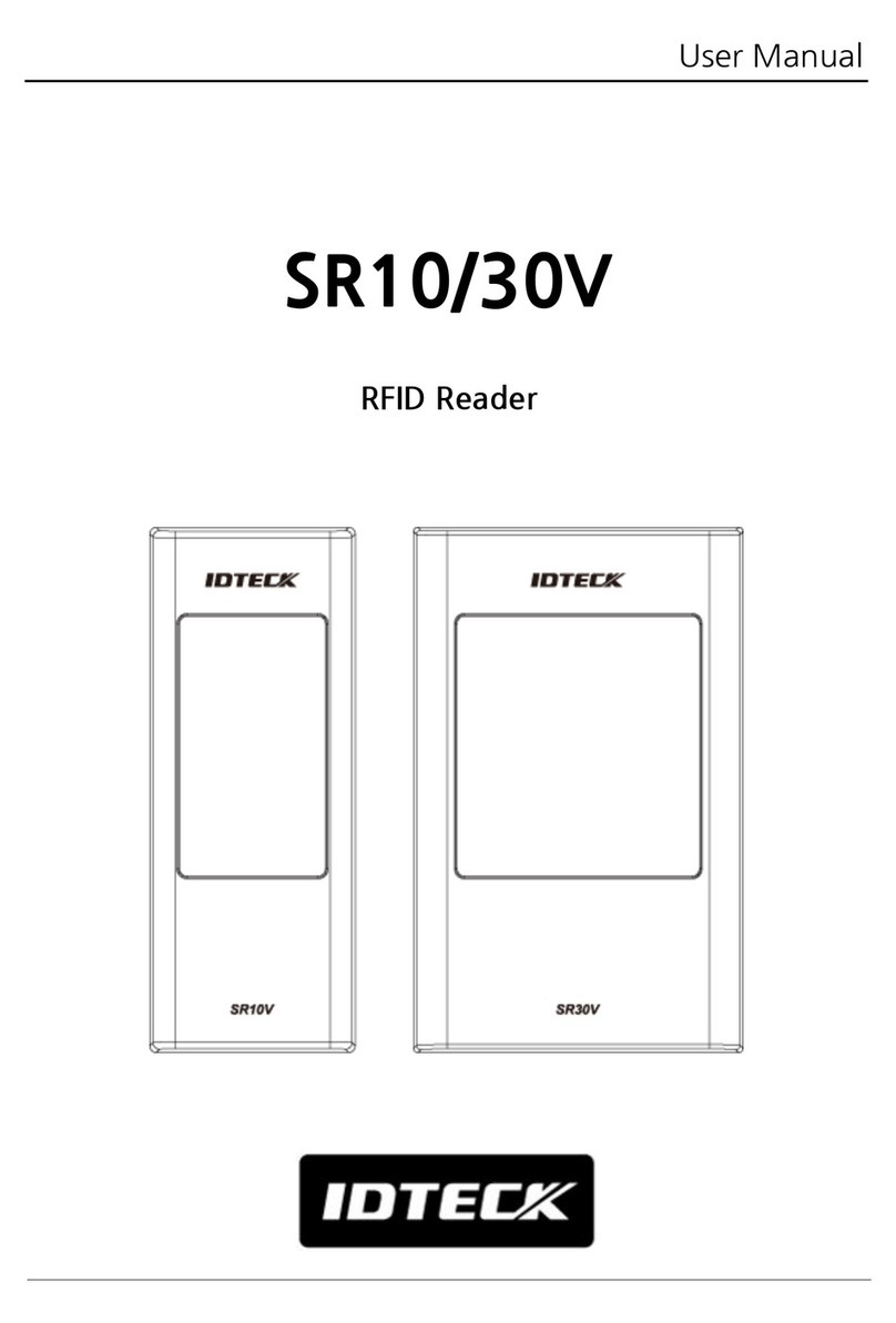
IDTECK SR10/30V User manual

IDTECK
IDTECK Star RF TINY User manual

IDTECK
IDTECK SR10S User manual

IDTECK
IDTECK Star RF10 User manual

IDTECK
IDTECK PROX10 User manual

IDTECK
IDTECK RF900I-8 User manual

IDTECK
IDTECK Star SR10 User manual

IDTECK
IDTECK Star RFK101 User manual

IDTECK
IDTECK Star RFK101 User manual

IDTECK
IDTECK SRK101 User manual

IDTECK
IDTECK Star FINGER006 User manual
IDTECK
IDTECK Star RFK101 User manual
IDTECK
IDTECK Star RFK505 User manual

IDTECK
IDTECK NEO RF245 User manual
IDTECK
IDTECK Star RFK505 User manual

IDTECK
IDTECK NEO RF245 User manual
IDTECK
IDTECK Star SR10 User manual