IDTECK ipass IP10 User manual


Table of Contents
ii
Table of Contents
1 Safety Information
1 IMPORTANT SAFETY INSTRUCTIONS
2 General
3 Features
4 Identifying Supplied Parts
5 Specification
6 Check Points and Tip
7 Installation
8 Wire Color Table of the Reader
9 Wire Connection to Controller
10 Operation
11 FCC REGISTRATION INFORMATION
12 RMA Request
. . . . . . . . . . . . . . . . . . . . . . . . . . . . . . . . . . . . . . . . . . . . . . . . . . . . . . ii
. . . . . . . . . . . . . . . . . . . . . . . . . . . . . . . . . . . . . . . . . . . . . . . . . . . 1
. . . . . . . . . . . . . . . . . . . . . . . . . . . . . . . . . . . . . . . . . 3
. . . . . . . . . . . . . . . . . . . . . . . . . . . . . . . . . . . . . . . . . . . . . . . . . . . . . . . . . . . 4
. . . . . . . . . . . . . . . . . . . . . . . . . . . . . . . . . . . . . . . . . . . . . . . . . . . . . . . . . . . 5
. . . . . . . . . . . . . . . . . . . . . . . . . . . . . . . . . . . . . . . . . . . . . 6
. . . . . . . . . . . . . . . . . . . . . . . . . . . . . . . . . . . . . . . . . . . . . . . . . . . . . . . 7
. . . . . . . . . . . . . . . . . . . . . . . . . . . . . . . . . . . . . . . . . . . . . . . . . 8
. . . . . . . . . . . . . . . . . . . . . . . . . . . . . . . . . . . . . . . . . . . . . . . . . . . . . . . . . 10
. . . . . . . . . . . . . . . . . . . . . . . . . . . . . . . . . . . . . . . . . 11
. . . . . . . . . . . . . . . . . . . . . . . . . . . . . . . . . . . . . . . . . 12
. . . . . . . . . . . . . . . . . . . . . . . . . . . . . . . . . . . . . . . . . . . . . . . . . . . . . . . . 13
. . . . . . . . . . . . . . . . . . . . . . . . . . . . . . . . . . . . 14
. . . . . . . . . . . . . . . . . . . . . . . . . . . . . . . . . . . . . . . . . . . . . . . . . . . . . 15

Safety Information 1
p.1
CAUTION: TO REDUCE THE RISK OF ELECTRIC SHOCK, DO NOT REMOVE COVER
(OR BACK) NO USER SERVICEABLE PARTS INSIDE. REFER SERVICING TO QUALIFIE
D SERVICE PERSONNEL.
This symbol indicates that dangerous voltage consisting a risk of electric shock is pres
ent within this unit.
This exclamation point symbol is intended to alert the user to the presence of importa
nt operating and maintenance (servicing) instructions in the literature accompanying the ap
pliance.
WARNING
To reduce the risk of fire or electric shock, do not expose this appliance to rain or moisture.
WARNING
1. Be sure to use only the standard adapter that is specified in the specification sheet. Usin
g any other adapter could cause fire, electrical shock, or damage to the product.
2. Incorrectly connecting the power supply or replacing battery may cause explosion, fire,
electric shock, or damage to the product.

Safety Informationp.2
3. Do not connect multiple controllers to a single adapter. Exceeding the capacity may cau
se abnormal heat generation or fire.
4. Securely plug the power cord into the power receptacle. Insecure connection may caus
e fire.
5. When installing the controller, fasten it securely and firmly. The fall of controller may ca
use personal injury.
6. Do not place conductive objects (e.g. screwdrivers, coins, metal parts, etc.) or container
s filled with water on top of the controller. Doing so may cause personal injury due to fi
re, electric shock, or falling objects.
7. Do not install the unit in humid, dusty, or sooty locations. Doing so may cause fire or el
ectric shock.
8. If any unusual smells or smoke come from the unit, stop using the product. In such case,
immediately disconnect the power source and contact the service center. Continued us
e in such a condition may cause fire or electric shock.
9. If this product fails to operate normally, contact the nearest service center. Never disass
emble or modify this product in any way. (SAMSUNG is not liable for problems caused
by unauthorized modifications or attempted repair.)
10. When cleaning, do not spray water directly onto parts of the product. Doing so may ca
use fire or electric shock.
CAUTION
1. Do not drop objects on the product or apply strong blows to it. Keep away from a locat
ion subject to excessive vibration or magnetic interference.
2. Do not install in a location subject to high temperature (over 50°C), low temperature (b
elow -30°C), or high humidity. Doing so may cause fire or electric shock.
3. If you want to relocate the already installed product, be sure to turn off the power and
then move or reinstall it.
4. Remove the power plug from the outlet when there is a lighting storm. Neglecting to d
o so may cause fire or damage to the product.
5. Keep out of direct sunlight and heat radiation sources. It may cause fire.
6. Install it in a place with good ventilation.
7. Avoid aiming the controller directly towards extremely bright objects such as sun.
8. Apparatus shall not be exposed to dripping or splashing and no objects filled with liqui
ds, such as vases, shall be placed on the apparatus.
9. The Mains plug is used as a disconnect device and shall stay readily operable at any tim
e.

p.3IMPORTANT SAFETY INSTRUCTIONS
1IMPORTANT SAFETY INSTRUCTIONS
1. Read these instructions.
2. Keep these instructions.
3. Heed all warnings.
4. Follow all instructions.
5. Do not use this apparatus near water.
6. Clean only with dry cloth.
7. Do not block any ventilation openings. Install in accordance with the manufacturer’s ins
tructions.
8. Do not install near any heat sources such as radiators, heat registers, or other apparatus
(including amplifiers) that produce heat.
9. Do not defeat the safety purpose of the polarized or grounding-type plug. A polarized
plug has two blades with one wider than the other. A grounding type plug has two bla
des and a third grounding prong. The wide blade or the third prong is provided for you
r safety. If the provided plug does not fit into your outlet, consult an electrician for repla
cement of the obsolete outlet.
10. Protect the power cord from being walked on or pinched particularly at plugs, convenie
nce receptacles, and the point where they exit from the apparatus.
11. Only use attachments/accessories specified by the manufacturer.
12. Use only with cart, stand, tripod, bracket, or table specified by the manufacturer, or sol
d with the apparatus.
13. Unplug this apparatus when a card is used. Use caution when moving the cart/ apparat
us combination to avoid injury from tip-over.
14. Refer all servicing to qualified service personnel. Servicing is required when the apparat
us has been damaged in any way, such as power supply cord or plug is damaged, liquid
has been spilled or objects have fallen into the apparatus, the apparatus has been expo
sed to rain or moisture, does not operate normally, or has been dropped.

General 2
p.4
The iPASS IP10/20 is an elegant looking proximity reader. It can be easily mounted to metal
door frame (mullion) or any flat wall surface. The iPASS IP10/20 is a credible product with e
poxy potting that enables you to install it outside.

Features 3
p.5
●125KHz Proximity Card Reader
●ASK [EM] Format
●Read Range: Up to 4inch (10cm)
●User Format Available
●Output Format: 26bit Wiegand (Default), RS232 (Optional, Simultaneous output of 26b
it Wiegand and RS232)
●Easy to Install on Metal Door Frame or Mullion (IP10) and Wall Mount (IP20) Suitable
●External LED Control and External Buzzer Control
●Solid Epoxy Potted
●Waterproof (IP65 / IP66)
●Reverse Polarity Protection

Identifying Supplied Parts 4
p.6
Please unpack and check the contents of the box.

Specification 5
p.7
Model IP10 IP20
Read Range IPK50: Up to 2 inches (5cm)IPC170 / IPC180: Up to 4 inches (10cm)
Reading Time (Card) 30ms
Power / Current DC 12V / Max.150mA
Input Port 2 ports (External LED Control, External Buzzer Control)
Output Format 26bit Wiegand (Default), RS232 (Optional)
LED Indicator 2 Color LED (Red and Green)
Beeper Piezo Buzzer
Operating Temperature -35 to +65C ( -31 to +149F )
Operating Humidity 10% to 90% relative humidity non-condensing
Color / Material Dark Pearl Gray / Polycarbonate
Dimension
(W x H x T)
46mm x 122mm x 23mm
(1.82” x 4.81” x 0.87”)
76mm x 124mm x 23.5mm
(3” x 4.89” x 0.87”)
Weight 160g (0.35lbs) 185g (0.41lbs)
Warranty Life time
Index of Protection IP65 / IP66
Certification FCC, CE, RoHS

Check Points and Tip 6
p.8
●Recommended cable type and permissible length of cable
Description Cable Specification Maximum
Distance
Reader (Power and Data)
Reader -> ACU
Belden #9512, 22 AWG
4 conductor, shielded
150m
Belden #9514, 22 AWG
8 conductor, shielded
* Need thicker wire if you connect the reader with high current consumption.
●Reader connection
If you install the reader in a long distance between the ACU and the reader, you have to
remind that there will be a voltage drop between both ends of GND wire. For example, i
f you connect a reader with 100mA current consumption at 100m distance (assume to
using DC resistance of cable of 100Ω/100m) and the reader power is supplied from the
ACU, the voltage drop of the GND wire will be 1V. In this case, the Wiegand data signal
cannot be measured lower than 1V.
The most of ACU is capturing the signal by the voltage level of data input and 1V is the
critical point whether the ACU read the data logic “1” or logic “0” therefore the reader o
utput cannot be read correctly from the ACU.
You have to think about how you reduce the voltage drop between both ends of GND
wire. There will be two methods to reduce the voltage drop and ACU can read data corr
ectly.
○Reduce the DC resistance of GND wire; Using thick cable or add more wires to GND
wire in parallel. If you connect 4 wires in parallel for GND, the DC resistance of GND

p.9
wire will be reduced to 1/4 of single wire.
○Use separate power for the reader; Disconnect +12V wire from the ACU and conne
ct external power supply to the reader nearby then there will be no current flow thr
ough the GND wire and no voltage drop between both ends of GND wire.

Installation 7
p.10
1. Mullion/Wall Mount
Drill two 6-32 or M3 holes 3.3"(8.38cm) apart in vertical and drill one 1/2" hole for the r
eader
cable 1.7"(4.31cm) apart from the top hole.
(Skip this step, if you have installed an electric gang box.)
2. Put reader cable into the center hole and install the reader module by using two 6-32 o
r M3 screws (Not included).
3. Put bezel on to the reader module. Then push bezel until you hear the locking sound.
4. To detach the bezel, hold both sides of the bezel, push the bezel to the bottom, and pu
ll the bezel forward.

Wire Color Table of the Reader 8
p.11

Wire Connection to Controller 9
p.12

Operation 10
p.13
1. Once the power is applied, three beeping sounds can be heard and the LED toggles the
color to red-green-red indicating that the reader is in standby mode after a successful in
itialization and diagnostics
2. Present proximity card to the reader until you hear a beep sound. The LED is changing t
he color to Green simultaneously and sends the RF card data to the controller. Afterwar
ds the LED changes the color to red again for the next reading.
3. LED Control:
To change the LED colors, you may connect the LED Control Input (Yellow wire) to pow
er ground. The green LED is indicating that the reader is in standby mode.
Present proximity card. The LED changes the color to red simultaneously, then to green
again for the next reading.
4. Buzzer Control:
When the reader reads the proximity card, one beep sound generates in normal operati
on mode, but you can generate more beep sounds to distinguish whether the access is
granted or denied.
To generate more beeps, you may control the Buzzer Control Input (Blue wire) to power
ground.
Afterwards you can turn the beeper on, while holding the Buzzer Control Input to powe
r ground.

FCC REGISTRATION INFORMATION 11
p.14
FCC Requirements Part 15
Caution: Any changes or modifications in construction of this device which are not expressly
approved by the responsible for compliance could void the user's authority to operate the e
quipment.
NOTE: This device complies with Part 15 of the FCC rules.
Operation is subject to the following two conditions;
1. This device may not cause harmful interface, and
2. This device must accept any interference received, including interference that may caus
e undesired operation.
This equipment has been tested and found to comply with the limits for a Class A Digital De
vice, pursuant to Part 15 of the FCC rules. These limits are designed to this equipment gener
ates, uses, and can radiate radio frequency energy and, if not installed and used in accordan
ce with the instructions, may cause harmful interference to radio communications.
1. Reorient or relocate the receiving antenna.
2. Increase the separation between the equipment and receiver.
3. Connect the equipment into an outlet on another circuit.
4. Consult the dealer or an experienced radio/TV technician for help.

RMA Request 12
p.15
If you have any questions or problems regarding the RMA services, please contact us using t
he contact information below. Friendly representatives at IDTECK are always standing by to
provide the best after sales services.
IDTECK Headquarter
5F, Ace Techno Tower B/D, 684-1, Deungchon-Dong,
Gangseo-Gu, Seoul, 157-030, Korea
Tel: +82 2 2659 0055
Fax: +82 2 2659 0086
E-mail: [email protected]
Website: www.idteck.com
E-Training Center: http://www.idtecktraining.com
IDTECK Production Facility and RMA Center
2F, 89-4Dodang-Dong, Weonmi-Gu,
Bucheon-Si, Gyeonggi-Do 420-130, Korea
Tel: +82 2 2659 0055
Fax: +82 2 2659 0086
E-mail: [email protected]
Website: www.idteck.com
E-Training Center: http://www.idtecktraining.com
The specifications contained in this manual are subject to change without notice at
any time.
This manual suits for next models
1
Table of contents
Other IDTECK Card Reader manuals

IDTECK
IDTECK Star SR10 User manual

IDTECK
IDTECK Star RFK505 User manual
IDTECK
IDTECK SRK101 User manual

IDTECK
IDTECK SR30 User manual

IDTECK
IDTECK FGR006 User manual
IDTECK
IDTECK Star FINGER006 User manual

IDTECK
IDTECK SR10S User manual

IDTECK
IDTECK PROX10 User manual

IDTECK
IDTECK NEO RF245 User manual
IDTECK
IDTECK SR30 User manual

IDTECK
IDTECK RF900I-8 User manual

IDTECK
IDTECK PROX10 User manual

IDTECK
IDTECK SR10/30V User manual

IDTECK
IDTECK SR10RW User manual

IDTECK
IDTECK Star RFK101 User manual

IDTECK
IDTECK Star RF30 User manual

IDTECK
IDTECK STAR RF70 User manual
IDTECK
IDTECK LX006 User manual
IDTECK
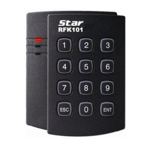
IDTECK Star RFK101 User manual

IDTECK
IDTECK NEO RF245 User manual