iDule ID1MB 2-UCL Series User manual

1.2Mega CMOS 2Head Camera
ID1MBx2-UCL (B/W)
ID1MCx2-UCL (COLOR)
Technical Manual
iDule Corporation

Table of Contents
PAGE
1. Product Outline ............................................................................................................................................ 3
2. Handling Precautions ................................................................................................................................... 3
3. Specification ................................................................................................................................................ 4
3.1.General Specification ....................................................................................................................................... 4
3.2.Camera Output Signal Specification .................................................................................................................. 6
3.3.Spectral Response (Representative Value) ......................................................................................................... 8
4. Connector ..................................................................................................................................................... 9
4.1.Connector P1 .................................................................................................................................................. 9
4.2.Connector P2 .................................................................................................................................................. 9
4.3.Connector CN1 ............................................................................................................................................... 9
4.4.Connector CN2 ............................................................................................................................................. 10
4.5.LED 1........................................................................................................................................................... 10
5. Timing Chart .............................................................................................................................................. 11
5.1. USB3.0 Normal Shutter Mode ........................................................................................................................ 11
5.2. USB3.0 Fixed Trigger Shutter Mode ................................................................................................................ 11
5.3.USB2.0 Normal Shutter Mode ......................................................................................................................... 12
5.4.USB2.0 Fixed Trigger Shutter Mode ................................................................................................................. 12
5.5.Camera Link 1Tap Base Configuration Normal Shutter Mode Horizontal Synchronous Signals Timing ..................... 13
5.6. Camera Link 1Tap Base Configuration Normal Shutter Mode Vertical Synchronous Signals Timing ........................ 14
5.7. Camera Link 1 Tap Base Configuration Fixed Trigger Shutter Mode Horizontal Synchronous Signals Timing ........... 15
5.8. Camera Link 1Tap Base Configuration Fixed Trigger Shutter Mode Vertical Synchronous Signals Timing ............... 15
5.9. Camera Link 2Tap Base Configuration Normal Shutter Mode Horizontal Synchronous Signals Timing .................... 16
5.10. Camera Link 2Tap Base Configuration Normal Shutter Mode Vertical Synchronous Signals Timing ...................... 16
5.12. Camera Link 2Tap Base Configuration Fixed Trigger Shutter Mode Horizontal Synchronous Signals Timing .......... 17
5.13. Camera Link 2Tap Base Configuration Fixed Trigger Shutter Mode Vertical Synchronous Signals Timing .............. 17
5.14. Camera Link Base Configuration 24bit – RGB Normal Shutter Mode Horizontal Synchronous Signals Timing ........ 18
5.15. Camera Link Base Configuration 24bit – RGB Normal Shutter Mode Vertical Synchronous Signals Timing............ 18
5.16. Camera Link Base Configuration 24bit – RGB Fixed Trigger Shutter Mode Horizontal Synchronous Signals Timing 19
5.17. Camera Link Base Configuration 24bit – RGB Fixed Trigger Shutter Mode Vertical Synchronous Signals Timing.... 19
5.18.Output Format ............................................................................................................................................ 20
5.19.Fixed Trigger Shutter Mode .......................................................................................................................... 22
6. Partial Scan Mode ...................................................................................................................................... 23
7. UVC Extension Units (USB) Remote Communication ............................................................................... 25
8. Serial Port (Camera Link) Remote Communication .................................................................................. 25
8.1.Command Specifications ................................................................................................................................ 26
8.2.Control Example ........................................................................................................................................... 30
9. Function Setting ............................................................................................................................................ 34
10. Dimensions ................................................................................................................................................... 38
11. Initial Setting ............................................................................................................................................. 39
12. Cases for Indemnity (Limited Warranty) .................................................................................................. 40
13. CMOS Pixel Defect ..................................................................................................................................... 40
14. Product Support ......................................................................................................................................... 40

1. Product Outline
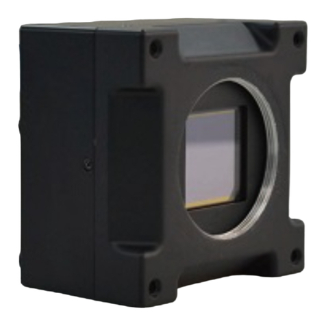
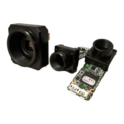
ID1MBX2-UCL/ID1MCX2-UCL is a Camera Link and USB3.0/2.0 interfaced and 1.2Mega resolution camera module.
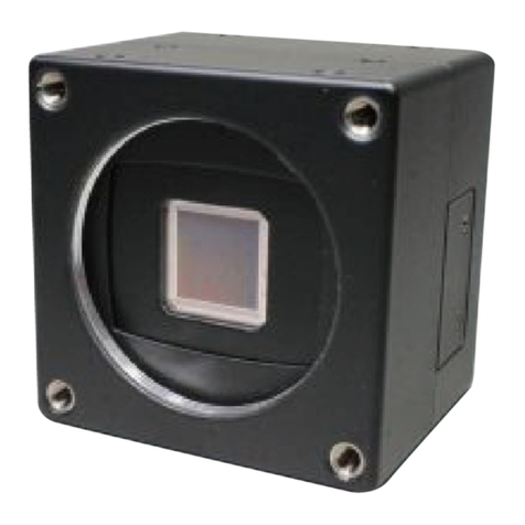
1.2Mega pixels CMOS sensor with diagonal length 6.0mm is utilized. Entire pixels can be read out
within 1/54s.
Features
□ Global Shutter CMOS sensor is utilized.
□ Camera Link Base Configuration is supported.
□ USB (UVC) YUV / RAW is supported.
□ External trigger shutter mode is operable.
□ USB Bus power, PoCL , 12pin power supply.
2. Handling Precautions
The camera must not be used for any nuclear equipment or aerospace equipment with which mechanical
failure or malfunction could result in serious bodily injury or loss of human life. Our warranty does not apply to
dameges or defects caused by irregular and /or abnormal use of the product.
Please observe all warnings and cautions stated below.
Our warranty does not apply to damages or malfunctions caused by neglecting these precautions.
Do not use or store the camera in the following extreme conditions :
- Extremely dusty or humid places.
- Extremely hot or cold places (operating temperature 0℃ to +40℃).
- Close to generators of powerful electromagnetic radiation such as radio or TV transmitters.
- Places subject to fluorescent light reflections.
- Places subject to unstable (flickering, etc.) lighting conditions.
- Places subject to strong vibration.
· Remove dust or dirt on the surface of the lens with a blower.
· Do not apply excessive force or static electricity that could damage the camera.
· Do not shoot direct images that are extremely bright (e.g., light source, sun, etc.), and when camera is not
in use, put the lens cap on.
· Confirm the mutual ground potential carefully and then connect the camera to monitors or computers.
AC leaks from the connected devices may cause damages or destroy the camera.
· Do not apply excessive voltage. (Use only the specified voltage.) Unstable or improper power supply
voltage may cause damages or malfunction of the camera.
· The voltage ripple of camera power DC +12V±10% shall be within ±50mV. Improper power supply
voltage may cause noises on the video signals.
· The rising time of camera power supply voltage shall be less than +10V, Max 60ms. Please avoid
noises like chattering when rising.

3. Specification
3.1.General Specification
(1) Image Sensor Type Diagonal length 6.0mm Global Shutter (OnSemi AR0135)
Effective Pixel Number 1288(H) x 972(V)
Cell Size 3.75μm(H) x 3.75μm(V)
Image Circle Φ6.0mm
(2) Video Output
Frequency
Pixel CLK USB : 74.25MHz
Camera Link : 74.25MHz
Output effective pixel number
2568(H) x 962(V)
USB3.0
UVC(YUV,RAW)
RAW8-RAW8*
USB2.0
UVC(YUV,RAW)
29.18fps
54.08fps
7.507fps
2572(H) x 989(V) : with Blanking
1388(H) x 989(V) : with Blanking
10000(H) x 989(V) : with Blanking
Camera Link
1Tap Base,24bit-RGB
2Tap Base
29.18fps
54.08fps
2572(H) x 989(V) : with Blanking
1388(H) x 989(V) : with Blanking
(3) Video Output USB3.0/2.0 : UVC (YUV,RAW),RAW8-RAW8
Camera Link : 1Tap Base Configuration, 2 Tap Base Configuration, Base Configuration 24bit – RGB
(4) Output Format Sensor AD 12bit
USB3.0/2.0
Camera Link
8bit
8bit / 10bit / 12bit
(5) Sensitivity B/W F11 2000lx
Color F8 2000lx
at shutter speed 1/29s(OFF), Gain 0dB
(6) Minimum
Illumination
B/W F1.4 2lx
Color F1.4 4lx
at shutter speed 1/29s(OFF), Gain +12dB
(7) Power Requirements USB Bus Power : DC+5V±5%
12pin / PoCL : DC+12V±10%
(8) Power Consumption typ 2.7 W
max 3.3 W
(9) Dimensions CHU : φ14.0mm L:54.0mm excluding projection
Head Cable : φ3.0mm L:2000mm
CCU : W:96.0mm D:50.0mm H:25mm excluding projection
(10) Weights Approx. 145g (CHU:7g)
(11) Lens Mount M12 Mount
(12) Gain 0dB ~ +12dB
(13) Shutter Speed USB3.0
UVC(YUV,RAW) : OFF(1/29s) ~ 1/29000s
RAW8-RAW8
Normal Shutter Mode : OFF(1/54s) ~ 1/54000s
Fixed Trigger Shutter Mode : OFF(1/45s) ~ 1/45000s
USB2.0
UVC(YUV,RAW) : OFF(1/7.5s) ~ 1/7500s
Camera Link
1Tap Base,24bit-RGB : OFF(1/29s) ~ 1/29000s
2Tap Base
Normal Shutter Mode : OFF(1/54s) ~ 1/54000s
Fixed Trigger Shutter Mode : OFF(1/45s) ~ 1/45000s
(14) Trigger Mode Fixed Trigger Shutter Mode *USB2.0 -> No Function
(15) Partial Scan Full Frame ~ 8 Line Partial Area : 1area

(16) Safety/
Quality Standards
CE To be applied for EN61000-6-4:2007+A1:2011
To be applied for EN61000-6-2:2005
RoHS: Conform to RoHS
(17) Durability Vibration 20~200 Hz, 98m/s2 (10G), X,Y and Z directions (120 min for each direction)
Shock No malfunction shall be occurred with 980m/s2 (100G) for ±X,±Y,±Z, 6 directions.
(without package)
(18) Environment Operation 0℃ ~ +40℃ Humidity 0 ~ 90%RH
Storage -25℃ ~ +65℃ Humidity 0 ~ 90%RH

3.2.Camera Output Signal Specification
3.2.1. USB3.0 / 2.0
(1)Video Output Data Effective Video Output 2568(H) × 962(V)
(2)Video Signals White Clip Level
F
Fh (at gain 0dB)
Setup Level
Under
0Ch
Dark Sharding
Both horizontal and vertical should
be under
00Fh
3.2.2. Camera Link
(1)Video Output Data Effective Video Output 2568(H) × 962(V)
(2)Sync Signal Output LVAL Camera Link (LVDS)
FVAL
DVA
SP(Exposure Signal)
(3)Camera Control
Signal Input
CC2・CC3・CC4 Camera Link Input(LVDS)
(4)Trigger Input Polarity Positive/Negative Selectable (Address 05)
CC1 Camera Link Input (LVDS) (Address 06)
(5)Serial
Communication
SerTC Camera Link (LVDS) (Serial to Camera)
SerTFG Camera Link (LVDS) (Serial to Frame Grabber)
(6)Video Signals
White Clip Level
F
FEh (at Gain 0dB, 12bit)
Setup Level
under
0C0h
Dark Shading
Both horizontal and vertical should be
under
0FFh
3.2.3. External Input / Output
(1)Trigger in CN1 CN1 : 1pin Low1.4V(max),High3.3V~5.0V (Address 06)
Polarity Positive / Negative (Address 05)
(2)Trigger in CN2 CN2 : 11pin Low1.4V(max),High3.3V~5.0V (Address 06)
Polarity Positive / Negative (Address 05)
(3)Exposure signal CN2 CN2 : 6pin Low0.55V(max),High3.8V(min)
(4)FVAL signal CN2 CN2 : 7pin Low0.55V(max),High3.8V(min)

Trigger in CN1(2pin), CN2(12pin)
Exposure signal CN2 / FVAL signal CN2
5.0V
100Ω
SN74LVC1G14
(TI)
1.0KΩ
CN1 1pin
CN2 11pin
(Input)
Signal
2.2KΩ
2.2KΩ
Delay approx 50 ns.
5.0V
100Ω
SN74LVC1G32
(TI)
CN1 6pin,7pin
(Output)
5.0V
1KΩ
Signal
1KΩ
10KΩ
2SC4116
Delay approx 1.2μs.

3.3.Spectral Response (Representative Value)
ID1MBX2-UCL (B/W)
ID1MCX2-UCL (Color)

4. Connector
CN1 CN2 LED
Camera1 Camera2 P2 P1
4.1.Connector P1
USB3.0 Micro B Connector
USB Bus Power
4.2.Connector P2
Camera Link Connector 12226-1100-00PL (3M)
PoCL
4.3.Connector CN1
2pin external trigger in 53261-0271 (molex)
Pin NO Name
1 Trigger in
2 GND
1
53261-0271 : molex

4.4.Connector CN2
12pin external Input / Output Connector HR10A-10R-12PB(72) HIROSE
4.5.LED 1
Power LED
Lights up when the camera is operational.
If the power is not supplied or the camera is broken, LED will not light up.
You can turn off the LED by communication setting.
PIN NO
1 GND
2 Power Input (DC+12V)
3 GND
4 NC
5 GND
6 FVAL signal out
7 Exposure signal out
8 GND
9 NC
10 NC
11 Trigger in
12 GND

5. Timing Chart
5.1. USB3.0 UVC(YUV,RAW) Normal Shutter Mode
After CMOS sensor is finished to expose, start to translate USB data.
USB translate timing is not fixed.
5.2. USB3.0 UVC(YUV,RAW) Fixed Trigger Shutter Mode
After CMOS sensor is finished to expose, start to translate USB data.
Frame Rate depend on trigger timing and exposure time.
USB translate timing is not fixed.
USB Out
2470416 Pixel Data
(Head1 1284 + Head2 1284) × 962
Exposure Time 2572clk × Number of set lines
Exposure Time CLK 74.25 MHz
Frame rate 29.18 fps
USB Out
2470416 Pixel Data
(Head1 1284 + Head2 1284) × 962
Exposure Time 2572clk × Number of set lines
Exposure Time CLK 74.25 MHz

5.3.USB3.0 RAW8-RAW8 Normal Shutter Mode
UVC(YUV):Y -> CAMERA 1 RAW 8bit / UV -> CAMERA 2 RAW 8bit
After CMOS sensor is finished to expose, start to translate USB data.
USB translate timing is not fixed.
5.4.USB3.0 RAW8-RAW8 Fixed Trigger Shutter Mode
UVC(YUV):Y -> CAMERA 1 RAW 8bit / UV -> CAMERA 2 RAW 8bit
After CMOS sensor is finished to expose, start to translate USB data.
Frame Rate depend on trigger timing and exposure time.
USB translate timing is not fixed.
USB Out
1235208 Pixel Data
1284 × 962
Exposure Time 1388clk × Number of set lines
Exposure Time CLK 74.25 MHz
Frame rate 54.08 fps
USB Out
1235208 Pixel Data
1284 × 962
Exposure Time 1650clk × Number of set lines
Exposure Time CLK 74.25 MHz

5.5. USB2.0 UVC (YUV, RAW) Normal Shutter Mode
After CMOS sensor is finished to expose, start to translate USB data.
Frame Rate depend on trigger timing and exposure time.
USB translate timing is not fixed.
USB Out
2470416 Pixel Data
(Head1 1284 + Head2 1284) × 962
Exposure Time 10000clk × Number of set lines
Exposure Time CLK 74.25 MHz
Frame rate 7.507 fps

5.6. Camera Link 1Tap Base Normal Shutter Mode Horizontal Synchronous Signals Timing
5.7. Camera Link 1Tap Base Normal Shutter Mode Vertical Synchronous Signals Timing
LVAL Out
~
~
Effective Data : 2568 CLK4 CLK
DVAL Out
1H = 2572 CLK
~
~
Camera Link CLK : 74.25MHz
(Camera Link Port A) 1 2 ・ ・ ・ ・ ・ ・ ・
3 4
2
5
6
5
2
5
6
6
2
5
6
7
2
5
6
8
1
Video Out
~
~
2
2
5
6
7
2
5
6
8
3 4
2
5
6
5
2
5
6
6
~
~
~
~~
~
1
2
8
3
1
2
8
4
1
2
8
5
1
2
8
6
1
2
8
5
1
2
8
6
1
2
8
3
1
2
8
4
・ ・ ・ ・ ・ ・ ・
Head1 Head2
FVAL Out
1Frame = 989H (34.26ms)
Effective Line : 962H
DVAL Out
~
~
LVAL Out
~
~
~
~~
~
V Blanking : 27H
9
6
2
9
6
2
1 1
1H = 34.64 us
Video Out

5.8. Camera Link 1 Tap Base Fixed Trigger Shutter Mode Horizontal Synchronous Signals Timing
5.9. Camera Link 1Tap Base Fixed Trigger Shutter Mode Vertical Synchronous Signals Timing
LVAL Out
~
~
Effective Data : 2568 CLK4 CLK
DVAL Out
1H = 2572 CLK
~
~
Camera Link CLK : 74.25MHz
(Camera Link Port A) 1 2 ・ ・ ・ ・ ・ ・ ・
3 4
2
5
6
5
2
5
6
6
2
5
6
7
2
5
6
8
1
Video Out
~
~
2
2
5
6
7
2
5
6
8
3 4
2
5
6
5
2
5
6
6
~
~
~
~~
~
1
2
8
3
1
2
8
4
1
2
8
5
1
2
8
6
1
2
8
5
1
2
8
6
1
2
8
3
1
2
8
4
・ ・ ・ ・ ・ ・ ・
Head1 Head2
FVAL Out
1Frame = Exposure Time + 1024H (35.47ms)
Effective Line : 962H
DVAL Out
~
~
LVAL Out
~
~
~
~~
~
16.5H
9
6
2
9
6
2
1 1
1H = 34.64 us
Video Out
TRIG IN
(Exposure
Time)
Number of
set lines
18.5H V Blanking : 27H

5.10. Camera Link 2Tap Base 24bit-RGB Normal Shutter Mode Horizontal Synchronous Signals Timing
5.11. Camera Link 2Tap Base 24bit-RGB Normal Shutter Mode Vertical Synchronous Signals Timing
LVAL Out
Effective Data : 2568 CLK4 CLK
DVAL Out
1H = 2572 CLK
Camera Link CLK : 74.25MHz
R
1
Video Out
G
1
G
2
5
6
8
B
2
5
6
8
B
1
R
2
B
2
5
6
7
R
2
5
6
8
(Camera Link Port A) R1 R2 R2567 R2568
(Camera Link Port B) G1 G2 G2567 G2568
(Camera Link Port C) B1 B2 B2567 B2568
G
2
B
2
G
2
5
6
7
R
2
5
6
7
~
~
~
~
・ ・ ・ ・ ・ ・ ・
~
~
~
~
~
~~
~
Head2
R1284 R1285
G1284 G1285
B1284 B1285
G
1
2
8
5
B
1
2
8
5
B
1
2
8
4
R
1
2
8
5
G
1
2
8
4
R
1
2
8
4
・ ・ ・ ・ ・ ・ ・
Head1
FVAL Out
1Frame = 989H (34.26ms)
Effective Line : 962H
DVAL Out
~
~
LVAL Out
~
~
~
~~
~
V Blanking : 27H
9
6
2
9
6
2
1 1
1H = 34.64 us
Video Out

5.12. Camera Link Base 24bit-RGB Fixed Trigger Shutter Mode Horizontal Synchronous Signals Timing
5.13. Camera Link Base 24bit-RGB Fixed Trigger Shutter Mode Vertical Synchronous Signals Timing
LVAL Out
Effective Data : 2568 CLK4 CLK
DVAL Out
1H = 2572 CLK
Camera Link CLK : 74.25MHz
R
1
Video Out
G
1
G
2
5
6
8
B
2
5
6
8
B
1
R
2
B
2
5
6
7
R
2
5
6
8
(Camera Link Port A) R1 R2 R2567 R2568
(Camera Link Port B) G1 G2 G2567 G2568
(Camera Link Port C) B1 B2 B2567 B2568
G
2
B
2
G
2
5
6
7
R
2
5
6
7
~
~
~
~
・ ・ ・ ・ ・ ・ ・
~
~
~
~
~
~~
~
Head2
R1284 R1285
G1284 G1285
B1284 B1285
G
1
2
8
5
B
1
2
8
5
B
1
2
8
4
R
1
2
8
5
G
1
2
8
4
R
1
2
8
4
・ ・ ・ ・ ・ ・ ・
Head1
FVAL Out
1Frame = Exposure Time + 1024H (35.47ms)
Effective Line : 962H
DVAL Out
~
~
LVAL Out
~
~
~
~~
~
16.5H
9
6
2
9
6
2
1 1
1H = 34.64 us
Video Out
TRIG IN
(Exposure
Time)
Number of
set lines
18.5H V Blanking : 27H

5.14. Camera Link 2Tap Base Normal Shutter Mode Horizontal Synchronous Signals Timing
5.15. Camera Link 2Tap Base Normal Shutter Mode Vertical Synchronous Signals Timing
LVAL Out
~
~
Effective Data : 1284 CLK104 CLK
DVAL Out
1H = 1388 CLK
~
~
Camera Link CLK : 74.25MHz
(Camera Link Port A) 1・ ・ ・ ・ ・ ・ ・ ・ ・ ・ ・ ・
21283 1284
1
Video Out
~
~
1
1
2
8
4
1
2
8
4
2 2
1
2
8
3
1
2
8
3
(Camera Link Port B) 1 2 1283 1284
Head1
Head2
1Tap Base Configuration Output モード
FVAL Out
1Frame = 989H (18.49ms)
Effective Line : 962H
DVAL Out
~
~
LVAL Out
~
~
~
~~
~
V Blanking : 27H
9
6
2
9
6
2
1 1
1H = 18.694 us
Video Out

5.16. Camera Link Base Configuration 24bit – RGB Fixed Trigger Shutter Mode Horizontal Synchronous Signals Timing
5.17. Camera Link Base Configuration 24bit – RGB Fixed Trigger Shutter Mode Vertical Synchronous Signals Timing
LVAL Out
~
~
Effective Data : 1284 CLK366 CLK
DVAL Out
1H = 1650 CLK
~
~
Camera Link CLK : 74.25MHz
R
1
Video Out
~
~
G
1
G
1
2
8
4
B
1
2
8
4
B
1
R
2
B
1
2
8
3
R
1
2
8
4
(Camera Link Port A) R1 R2 R1283 R1284
(Camera Link Port B) G1 G2 ・ ・ ・ ・ ・ ・ ・ ・ ・ ・ ・ ・ G1283 G1284
(Camera Link Port C) B1 B2 B1283 B1284
G
2
B
2
R
1
2
8
3
G
1
2
8
3
FVAL Out
1Frame = Exposure Time + 1029H (22.87ms)
Effective Line : 962H
DVAL Out
~
~
LVAL Out
~
~
~
~~
~
21.5H
9
6
2
9
6
2
1 1
1H = 22.222 us
Video Out
TRIG IN
(Exposure
Time)
Number of
set lines
18.5H V Blanking : 27H

5.18.Output Format
USB3.0 / 2.0 UVC
ID1MBX2-UCL ID1MCX2-UCL (YUV)
ID1MCX2-UCL (RAW)
Camera Link 1Tap Base Configuration
ID1MBX2-UCL ID1MCX2-UCL
~
~~
~
962 Line
1284pixel
・・・Y1 V1 Y2 U2 Y
1284
U
1284
U2
(80h)
Y2 Y
1284
U
1284
・・・
V1
(80h)
~
~~
~
962 Line
1284pixel
Y1
~
~~
~
962 Line
1284pixel
・・・G2B1
G
1283
R
1284
G
1284
B
1283
G
1284
D
1283
D
1284
・・・D2
~
~~
~
962 Line
1284pixel
D1
U2
(80h)
RAW
G2
RAW
G
1284
U1284
(80h)
・・・
V1
(80h)
~
~~
~
962 Line
1284pixel
RAW
B1
RAW
R
1284
U1284
(80h)
RAW
G
1283
V1283
(80h)
This manual suits for next models
1
Table of contents
Other iDule Digital Camera manuals

iDule
iDule ID50MB-OPT User manual

iDule
iDule ID2MB-CLIR User manual

iDule
iDule ID2MB-CLD User manual

iDule
iDule ID4MUVG-CL User manual

iDule
iDule ID2MB-CL User manual

iDule
iDule ID25MGB-CL User manual

iDule
iDule ID50MB-CL User manual

iDule
iDule ID8MUVS-CL User manual

iDule
iDule ID1MB-BRDCS-U User manual

iDule
iDule ID3MB-CL User manual

iDule
iDule ID5MGB-CL User manual

iDule
iDule ID4MB-CLD User manual

iDule
iDule ID9MGB-CL User manual

iDule
iDule ID25MB-CL User manual

iDule
iDule ID4MUVG2-CL User manual

iDule
iDule ID4MB-CL User manual

iDule
iDule ID65MB-CL User manual

iDule
iDule ID1MB-BRDC-U User manual

iDule
iDule ID4MUV-CL User manual

iDule
iDule ID5MB-CL User manual