iDule ID8MUVS-CL User manual

8M UV CMOS Camera
ID8MUVS-CL (B/W)
Technical Manual
iDule Corporation

Table of Contents
PAGE
1. Product Outline ............................................................................................................................................ 3
2. Handling Precautions ................................................................................................................................... 3
3. Specification ................................................................................................................................................ 4
3.1. General Specification ..................................................................................................................................... 4
3.2. Camera Output Signal Specification ................................................................................................................. 5
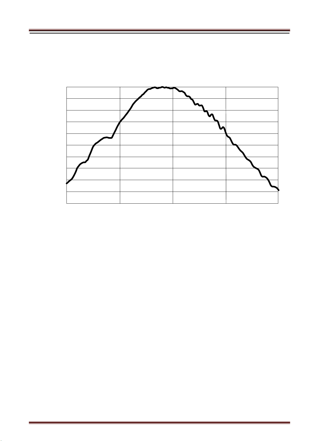
3.3. Spectral Response (Representative Value) ....................................................................................................... 6
4. Connector ..................................................................................................................................................... 7
4.1.Camera Link Connector 12226-1100-00PL (3M) ................................................................................................. 7
4.2. Power LED .................................................................................................................................................... 8
4.3. 12pin Connector HR10A-10R-12PB (HIROSE) (CN1) .......................................................................................... 8
4.4. Power input to camera ................................................................................................................................... 8
5. Timing Chart ................................................................................................................................................ 9
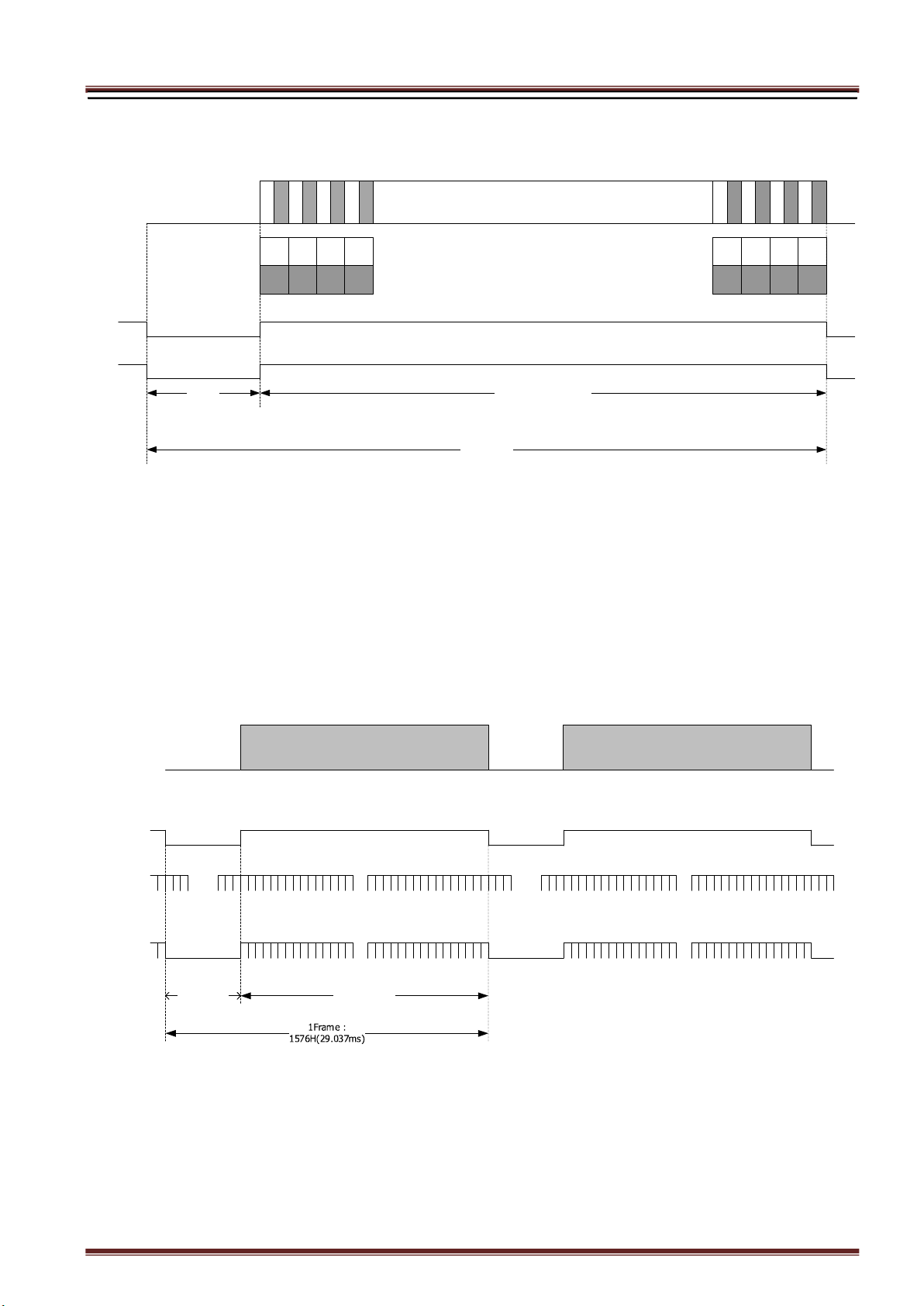
5.1. Horizontal Synchronous Signals Timing (2Tap Base Configuration : 10.2fps ) .................................................... 9
5.2. Vertical Synchronous Signals Timing (2Tap Base Configuration : 10.2fps) ......................................................... 9
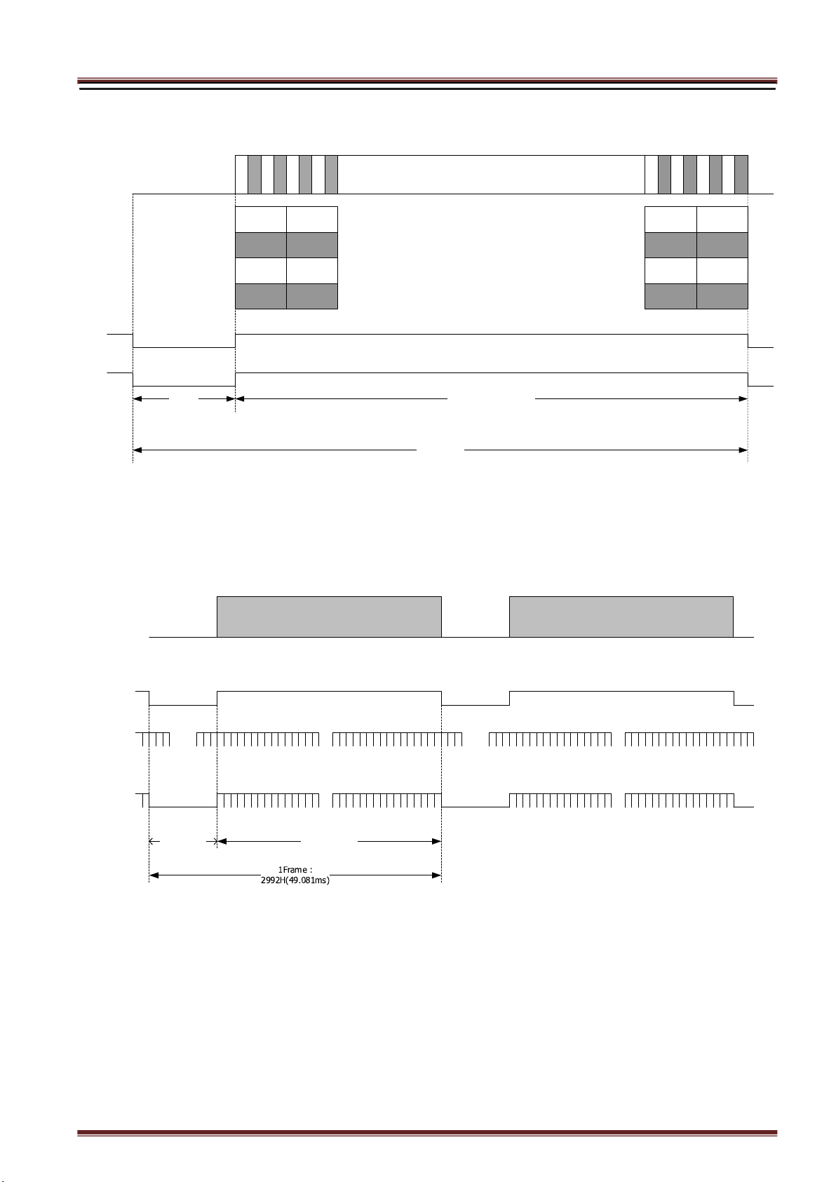
5.3. Horizontal Synchronous Signals Timing (2x2 binning 2Tap Base Configuration : 34.4fps) .................................. 10
5.4. Vertical Synchronous Signals Timing (2x2 binning 2Tap Base Configuration : 34.4fps) ................................... 10
5.5. Horizontal Synchronous Signals Timing (3Tap Base Configuration : 13.6fps) ................................................... 11
5.6. Vertical Synchronous Signals Timing (3Tap Base Configuration : 13.6fps) ....................................................... 11
5.7. Horizontal Synchronous Signals Timing (2x2 binning 3Tap Base Configuration : 45.9fps) .................................. 12
5.8. Vertical Synchronous Signals Timing (2x2 binning 3Tap Base Configuration : 45.9fps)...................................... 12
5.9. Horizontal Synchronous Signals Timing (4Tap Medium Configuration : 20.4fps) ............................................... 13
5.10. Vertical Synchronous Signals Timing (4Tap Medium Configuration : 20.4fps) ................................................. 13
5.11. Horizontal Synchronous Signals Timing (2x2 binning 4Tap Medium Configuration : 68.9fps) ............................ 14
5.12. Vertical Synchronous Signals Timing (2x2 binning 4Tap Medium Configuration : 68.9fps) ................................ 14
5.13. Horizontal Synchronous Signals Timing (8Tap Full Configuration : 40.7fps) .................................................... 15
5.14. Vertical Synchronous Signals Timing (8Tap Full Configuration : 40.7fps) ........................................................ 15
5.15. Horizontal Synchronous Signals Timing (2x2 Binning 8Tap Full Configuration : 137.8fps) ................................ 16
5.16. Vertical Synchronous Signals Timing (2x2 Binning 8Tap Full Configuration : 137.8fps) .................................... 16
5.17. Output format ............................................................................................................................................ 17
5.18. Fixed Trigger Shutter Mode ......................................................................................................................... 19
5.19. Pulse Width Trigger Shutter Mode ................................................................................................................ 20
6. Partial Scan Mode ...................................................................................................................................... 21
7. Horizontal cutout function ........................................................................................................................ 23
8. Remote Communication ............................................................................................................................ 24
8.1. Command Specifications ............................................................................................................................... 25
8.2. Control Example .......................................................................................................................................... 29
9. Function Setting ......................................................................................................................................... 33
10. Dimensions................................................................................................................................................. 36
11. Initial Setting ............................................................................................................................................. 37
12. Cases for Indemnity (Limited Warranty) .................................................................................................. 38
13. CMOS Pixel Defect ..................................................................................................................................... 38
14. Product Support ......................................................................................................................................... 38

1. Product Outline
ID8MUVS-CL is a Camera Link interfaced and 8M resolution camera module.
8M pixels CMOS sensor with diagonal length 11.037 is utilized. Entire pixels can be read out
within 1/40.7s at Full Configuration output.
Features
□ Global Shutter CMOS sensor is utilized.
□ Camera Link Base , Medium, Full Configuration are supported.
□ Fixed trigger shutter mode, pulse width trigger shutter mode are operable.
□ Full frame rates are as follows.
2Tap Base Configuration 10.2fps 8bit/10bit/12bit
3Tap Base Configuration 13.6fps 8bit
4Tap Medium Configuration 20.4fps 8bit/10bit/12bit
8Tap Full Configuration* 40.7fps 8bit/10bit
2x2 binning 2Tap Base Configuration 34.4fps 8bit/10bit/12bit
2x2 binning 3Tap Base Configuration 45.9fps 8bit
2x2 binning 4Tap Medium Configuration 68.9fps 8bit/10bit/12bit
2x2 binning 8Tap Full Configuration 137.8fps 8bit/10bit
*Initial Setting : 8Tap Full Configuration (40.7fps, 8bit)
2. Handling Precautions
The camera must not be used for any nuclear equipment or aerospace equipment with which mechanical
failure or malfunction could result in serious bodily injury or loss of human life. Our warranty does not apply to
dameges or defects caused by irregular and /or abnormal use of the product.
Please observe all warnings and cautions stated below.
Our warranty does not apply to damages or malfunctions caused by neglecting these precautions.
Do not use or store the camera in the following extreme conditions :
- Extremely dusty or humid places.
- Extremely hot or cold places (operating temperature -5℃ to +45℃).
- Close to generators of powerful electromagnetic radiation such as radio or TV transmitters.
- Places subject to fluorescent light reflections.
- Places subject to unstable (flickering, etc.) lighting conditions.
- Places subject to strong vibration.
· Remove dust or dirt on the surface of the lens with a blower.
· Do not apply excessive force or static electricity that could damage the camera.
· Do not shoot direct images that are extremely bright (e.g., light source, sun, etc.), and when camera is not
in use, put the lens cap on.
· Confirm the mutual ground potential carefully and then connect the camera to monitors or computers.
AC leaks from the connected devices may cause damages or destroy the camera.
· Do not apply excessive voltage. (Use only the specified voltage.) Unstable or improper power supply
voltage may cause damages or malfunction of the camera.
· The voltage ripple of camera power DC +12V±10% shall be within ±50mV. Improper power supply
voltage may cause noises on the video signals.
· The rising time of camera power supply voltage shall be less than +10V, Max 60ms. Please avoid
noises like chattering when rising.

3. Specification
3.1. General Specification
(1) Image Sensor Device type Diagonal length 11.037mm, Global Shutter type (Sony
IMX487)
Effective pixel number 2848(H)
x
2848(V)
7.804
7.804
(単位:mm)
Unit cell size 2.74(H) x
2.74(V)
μm
Image circle Φ11.037
mm
(2) Video Output Frequency Pixel Clock 49.5MHz
2Tap Base Configuration 10.2fps 1624(H) x 2992(V) with blanking
3Tap Base Configuration 13.6fps 1218(H) x 2992(V) with blanking
4Tap Medium Configuration 20.4fps 812(H) x 2992(V) with blanking
8Tap Full Configuration 40.7fps 406(H) x 2992(V) with blanking
2x2binning 2Tap Base Configuration 34.4fps 912(H) x 1576(V) with blanking
2x2binning 3Tap Base Configuration 45.9fps 684(H) x 1576(V) with blanking
2x2binning 4Tap Medium Configuration 68.9fps 456(H) x 1576(V) with blanking
2x2binning 8Tap Full Configuration 137.8fps 228(H) x 1576(V) with blanking
(3) Video Output 2Tap Base Configuration
3Tap Base Configuration
4Tap Medium Configuration
8Tap Full Configuration (Initial Setting)
(4) Output Format Sensor AD 12bit
Camera Link Output
2Tap Base Configuration :8bit / 10bit / 12bit
3Tap Base Configuration :8bit
4Tap Medium Configuration:8bit / 10bit / 12bit
8Tap Full Configuration :8bit / 10bit
(5) Sensitivity B/W F8 2000lx
(at shutter speed 1/40.7s (OFF), Gain 0dB, 8tap Full Configuration)
(6) Power supply input voltage
DC+12V±10% 12 pin connector (Initial Setting) / PoCL
(7) Power Consumption max 2.9W (at 8Tap Full Configuration)
(8) Dimensions H:45mm W:45mm D:35mm excluding projection
(9) Weight Approx. 115g
(10) Lens Mount C mount
(11) Optical Axis Accuracy Refer to drawing for CMOS optical axis accuracy
(12) Gain Variable Range 0dB ~ +48dB (Guaranteed range)
(13) Shutter Speed Variable Range
2Tap Base Configuration :OFF(1/10s) ~ 1/6,000s
3Tap Base Configuration :OFF(1/14s) ~ 1/8,000s
4Tap Medium Configuration :OFF(1/20s) ~ 1/12,000s
8Tap Full Configuration :OFF(1/41s) ~ 1/23,000s
2x2binning 2Tap Base Configuration :OFF(1/38s) ~ 1/6,000s
2x2binning 3Tap Base Configuration :OFF(1/50s) ~ 1/8,000s
2x2binning 4Tap Medium Configuration :OFF(1/76s) ~ 1/12,000s
2x2binning 8Tap Full Configuration :OFF(1/152s)~ 1/23,000s
(14) Trigger Shutter Mode Fixed shutter trigger mode / Pulse width shutter trigger mode
(15) Partial Scan Mono : Full frame ~ 16Line (16Line/Step) 1area
(16) Binning Mode 2x2 binning (4 pixel addition ) mode ON/OFF
(17) Safety/Quality Standards RoHS : Confirm to RoHS

(18) Durability Vibration 20~200 Hz,98m/s2 (10G), X,Y and Z 3directions (120 min for each direction)
Shock No malfunction shall be occurred with 980m/s2 (100G) for ±X,±Y,and ±Z,
6 directions. (without package)
(19) Operation Environment Temperature -5 ~ +45℃ Humidity 20 ~ 80%RH with no condensation.
(20) Storage Environment Temperature -25 ~ +60℃ Humidity 20 ~ 80%RH with no condensation.
3.2. Camera Output Signal Specification
(1)Video Output Data Effective Video Output 2Tap Base Configuration
4Tap Medium Configuration
8Tap Full Configuration
3Tap Base Configuration
2x2binning 2Tap Base Configuration
2x2binning 4Tap Medium Configuration
2x2binning 8Tap Full Configuration
2x2binning 3Tap Base Configuration
: 2848(H) x 2848(V)
: 2848(H) x 2848(V)
: 2848(H) x 2848(V)
: 2784(H) x 2848(V)
: 1424(H) x 1424(V)
: 1424(H) x 1424(V)
: 1424(H) x 1424(V)
: 1392(H) x 1424(V)
(2)Sync Signal Output
LVAL Camera Link (LVDS)
FVAL
DVAL
SP (Exposure output)
FVAL 12pin Connector 6pin (LVTTL)
Exposure 12pin Connector 10pin (LVTTL)
(3)Camera Control
Signal Input
CC2・CC3・CC4 Camera Link (LVDS) (No Function)
(4)Trigger Input Polarity Positive/Negative Selectable (Address 05h)
Pulse Width 1HD(Min) ~ (*)
2Tap Base Configuration :1HD (32.808us)
3Tap Base Configuration :1HD (24.606us)
4Tap Medium Configuration:1HD (16.404us)
8Tap Full Configuration :1HD ( 8.202us)
2x2binning 2Tap Base Configuration :1HD (18.424us)
2x2binning 3Tap Base Configuration :1HD (13.818us)
2x2binning 4Tap Medium Configuration :1HD ( 9.212us)
2x2binning 8Tap Full Configuration :1HD ( 4.606us)
*The trigger input signal is sampled n times HD in the camera, and the
exposure time is processed n times HD. Trigger pulses shorter than 1 HD are
treated as 1 HD wide.
Functionally, no upper limitation is set but noises such as dark noises and
shadings might be noticeable at long time exposure.
CC1(Trigger Input) Camera Link (LVDS) (Address 06h)
12pin Connector(Trigger Input)
12pin Connector 11pin Input (LVTTL)
(5)Serial
Communication
SerTC Camera Link (LVDS) (Serial to Camera)
SerTFG (Serial to Frame Grabber)
(6)Video Signals White Clip Level
FFh
(at Gain 0dB, 8bit)
Setup Level
under
002h
Dark Shading
Both horizontal and vertical should be under
0Fh

3.3. Spectral Response (Representative Value)
00%%
1100%%
2200%%
3300%%
4400%%
5500%%
6600%%
7700%%
8800%%
9900%%
110000%%
220000 440000 660000 880000 11000000
RReellaattiivvee RReessppoonnssee
WWaavveelleennggtthh [[ nnmm ]]
Spectral sensitivity characteristics

4. Connector
4.1.Camera Link Connector 12226-1100-00PL (3M)
Connector (P2) Connector (P1)
PIN
No
Name PIN
No
Name
PIN
No
Name PIN
No
Name
1 +12V(PoCL) 14 GND
1 +12V(PoCL) 14 GND
2 Y0- 15 Y0+
2 X0- 15 X0+
3 Y1- 16 Y1+
3 X1- 16 X1+
4 Y2- 17 Y2+
4 X2- 17 X2+
5 Yclk- 18 Yclk+
5 Xclk- 18 Xclk+
6 Y3- 19 Y3+
6 X3- 19 X3+
7 100Ω 20 Terminated
7 SerTC+ 20 SerTC-
8 Z0- 21 Z0+
8 SerTFG- 21 SerTFG+
9 Z1- 22 Z1+
9 CC1- (Trigger IN -)
22 CC1+ (Trigger IN +)
10 Z2- 23 Z2+
10 CC2+ 23 CC2-
11 Zclk- 24 Zclk+
11 CC3- 24 CC3+
12 Z3- 25 Z3+
12 CC4+ 25 CC4-
13 GND 26 +12V(PoCL)
(P1)(P2)
(CN1)
(Power LED)
(Base Configuration)
(Medium / Full Configuration)

4.2. Power LED
LED lights when the camera is operational. If the power is not supplied or the camera is broken, the LED will not light.
※ LED can be turned off (address 1Bh) by serial setting.
4.3. 12pin Connector HR10A-10R-12PB (HIROSE) (CN1)
4.4. Power input to camera
Camera rear 12pin connector (2pin) or Camera Link (PoCL) feeding is possible. (Because the power supply is diode-OR
connected, there is no problem even if it is powered simultaneously.)
PIN
No Name
IO(5V LVTTL)
100
Ω
FVAL Output
+5.0V(VCC)
External Trigger Input
SN74LVC1G32(TI)
Voh:3.8V(Min)
Vol:0.55V(Max)
1K
Ω
SN74LVC1G14(TI)
⊿
Vt-:0.71(Min)
⊿
Vt+:1.04V(Max)
100
Ω
11
100
Ω
SN74LVC1G32(TI)
Voh:3.8V(Min)
Vol:0.55V(Max)
Exposure Output
6
10
12pin
1 GND
2 Power in(DC+12V)
3 GND
4 NC
5 GND
6 FVAL out
7 NC
8 GND
9 NC
10 Exposure out
11 Trigger in
12 GND

5. Timing Chart
5.1. Horizontal Synchronous Signals Timing (2Tap Base Configuration : 10.2fps )
5.2. Vertical Synchronous Signals Timing (2Tap Base Configuration : 10.2fps)
LVAL Out
Effective Data : 1424 CLK200 CLK
DVAL Out
1H : 1624 CLK
Camera Link Port B ・ ・ ・ ・ ・ ・ ・ ・ ・ ・ ・ ・
Camera Link CLK : 49.500MHz
Camera Link Port A 0 2 ・ ・ ・ ・ ・ ・ ・
4 6
01
~
~
234567Image Out
1 3 5 7 ・ ・ ・ ・ ・ ・ ・
~
~
~
~
2
8
4
6
2
8
4
7
2
8
4
4
2
8
4
5
2
8
4
2
2
8
4
3
2
8
4
0
2
8
4
1
2840
28432841
2842 28462844
28472845
FVAL Out
Effective Line :
2848H
DVAL Out
~
~
LVAL Out
~
~
V Blanking :
144H
2
8
4
7
0
1H = 32.808us
~
~
Image Out
~
~~
~
2
8
4
7
0
~
~

5.3. Horizontal Synchronous Signals Timing (2x2 binning 2Tap Base Configuration : 34.4fps)
5.4. Vertical Synchronous Signals Timing (2x2 binning 2Tap Base Configuration : 34.4fps)
LVAL Out
Effective Data : 712 CLK200 CLK
DVAL Out
1H : 912 CLK
Camera Link Port B ・ ・ ・ ・ ・ ・ ・ ・ ・ ・ ・ ・
Camera Link CLK : 49.500MHz
Camera Link Port A 0 2 ・ ・ ・ ・ ・ ・ ・
4 6
01
~
~
234567Image Out
1 3 5 7 ・ ・ ・ ・ ・ ・ ・
~
~
~
~
1
4
2
2
1
4
2
3
1
4
2
0
1
4
2
1
1
4
1
8
1
4
1
9
1
4
1
6
1
4
1
7
1416
14191417
1418 14221420
14231421
FVAL Out
Effective Line :
1424H
DVAL Out
~
~
LVAL Out
~
~
V Blanking :
152H
1
4
2
3
0
1H = 18.424us
~
~
Image Out
~
~~
~
1
4
2
3
0
~
~

5.5. Horizontal Synchronous Signals Timing (3Tap Base Configuration : 13.6fps)
5.6. Vertical Synchronous Signals Timing (3Tap Base Configuration : 13.6fps)
LVAL Out
Effective Data : 928 CLK290 CLK
DVAL Out
1H : 1218 CLK
Camera Link Port B
・ ・ ・ ・ ・ ・ ・ ・ ・ ・ ・ ・
Camera Link
CLK : 49.500MHz
Camera Link Port A
・ ・ ・ ・ ・ ・ ・
~
~
Image Out
・ ・ ・ ・ ・ ・ ・
~
~
~
~
Camera Link Port C
・ ・ ・ ・ ・ ・ ・ ・ ・ ・ ・ ・
・ ・ ・ ・ ・ ・ ・
0
2
4
6
01234567
1
3
5
7
8
8
2775
2
7
8
2
2
7
8
3
2
7
8
0
2
7
8
1
2
7
7
8
2
7
7
9
2
7
7
6
2
7
7
7
2776 2779
2777
2778
2782
2780 2783
2781
2
7
7
5
FVAL Out
Effective Line :
2848H
DVAL Out
~
~
LVAL Out
~
~
V Blanking :
144H
2
8
4
7
0
1H = 24.606us
~
~
Image Out
~
~~
~
2
8
4
7
0
~
~

5.7. Horizontal Synchronous Signals Timing (2x2 binning 3Tap Base Configuration : 45.9fps)
5.8. Vertical Synchronous Signals Timing (2x2 binning 3Tap Base Configuration : 45.9fps)
LVAL Out
Effective Data : 464 CLK220 CLK
DVAL Out
1H : 684 CLK
Camera Link Port B
・ ・ ・ ・ ・ ・ ・ ・ ・ ・ ・ ・
Camera Link
CLK : 49.500MHz
Camera Link Port A
・ ・ ・ ・ ・ ・ ・
~
~
Image Out
・ ・ ・ ・ ・ ・ ・
~
~
~
~
Camera Link Port C
・ ・ ・ ・ ・ ・ ・ ・ ・ ・ ・ ・
・ ・ ・ ・ ・ ・ ・
0
2
4
6
01234567
1
3
5
7
8
8
1383
1
3
9
0
1
3
9
1
1
3
8
8
1
3
8
9
1
3
8
6
1
3
8
7
1
3
8
4
1
3
8
5
1384 1387
1385
1386
1390
1388 1391
1389
1
3
8
3
FVAL Out
Effective Line :
1424H
DVAL Out
~
~
LVAL Out
~
~
V Blanking :
152H
1
4
2
3
0
1H = 13.818us
~
~
Image Out
~
~~
~
1
4
2
3
0
~
~

5.9. Horizontal Synchronous Signals Timing (4Tap Medium Configuration : 20.4fps)
5.10. Vertical Synchronous Signals Timing (4Tap Medium Configuration : 20.4fps)
LVAL Out
Effective Data : 712 CLK100 CLK
DVAL Out
1H : 812 CLK
Camera Link Port B
・ ・ ・ ・ ・ ・ ・ ・ ・ ・ ・ ・
Camera Link
CLK : 49.500MHz
Camera Link Port A
・ ・ ・ ・ ・ ・ ・
~
~
Image Out
・ ・ ・ ・ ・ ・ ・
~
~
~
~
Camera Link Port C
・ ・ ・ ・ ・ ・ ・
Camera Link Port D
・ ・ ・ ・ ・ ・ ・
0
2
4
6
01234567
1
3
5
7
2
8
4
6
2
8
4
7
2
8
4
4
2
8
4
5
2
8
4
2
2
8
4
3
2
8
4
0
2
8
4
1
2840
2843
2841
2842 2846
2844
2847
2845
FVAL Out
Effective Line :
2848H
DVAL Out
~
~
LVAL Out
~
~
V Blanking :
144H
2
8
4
7
0
1H = 16.404us
~
~
Image Out
~
~~
~
2
8
4
7
0
~
~

5.11. Horizontal Synchronous Signals Timing (2x2 binning 4Tap Medium Configuration : 68.9fps)
5.12. Vertical Synchronous Signals Timing (2x2 binning 4Tap Medium Configuration : 68.9fps)
LVAL Out
Effective Data : 356 CLK100 CLK
DVAL Out
1H : 456 CLK
Camera Link Port B
・ ・ ・ ・ ・ ・ ・ ・ ・ ・ ・ ・
Camera Link
CLK : 49.500MHz
Camera Link Port A
・ ・ ・ ・ ・ ・ ・
~
~
Image Out
・ ・ ・ ・ ・ ・ ・
~
~
~
~
Camera Link Port C
・ ・ ・ ・ ・ ・ ・
Camera Link Port D
・ ・ ・ ・ ・ ・ ・
0
2
4
6
01234567
1
3
5
7
1
4
2
2
1
4
2
3
1
4
2
0
1
4
2
1
1
4
1
8
1
4
1
9
1
4
1
6
1
4
1
7
1416
1419
1417
1418 1422
1420
1423
1421
FVAL Out
Effective Line :
1424H
DVAL Out
~
~
LVAL Out
~
~
V Blanking :
152H
1
4
2
3
0
1H = 9.212us
~
~
Image Out
~
~~
~
1
4
2
3
0
~
~

5.13. Horizontal Synchronous Signals Timing (8Tap Full Configuration : 40.7fps)
5.14. Vertical Synchronous Signals Timing (8Tap Full Configuration : 40.7fps)
LVAL Out
Effective Data : 356 CLK50 CLK
DVAL Out
1H : 406 CLK
Camera Link Port B
・ ・ ・ ・ ・ ・ ・ ・ ・ ・ ・ ・
Camera Link
CLK : 49.500MHz
Camera Link Port A
・ ・ ・ ・ ・ ・ ・
~
~
Image Out
・ ・ ・ ・ ・ ・ ・
~
~
~
~
Camera Link Port C
・ ・ ・ ・ ・ ・ ・
Camera Link Port D
・ ・ ・ ・ ・ ・ ・
Camera Link Port F
・ ・ ・ ・ ・ ・ ・ ・ ・ ・ ・ ・
Camera Link Port E
・ ・ ・ ・ ・ ・ ・
・ ・ ・ ・ ・ ・ ・
Camera Link Port G
・ ・ ・ ・ ・ ・ ・
Camera Link Port H
・ ・ ・ ・ ・ ・ ・
0
2
4
6
01234567
1
3
5
7
2
8
4
6
2
8
4
7
2
8
4
4
2
8
4
5
2
8
4
2
2
8
4
3
2
8
4
0
2
8
4
1
2846
2847
2844
2845
2842
2843
2840
2841
FVAL Out
Effective Line :
2848H
DVAL Out
~
~
LVAL Out
~
~
V Blanking :
144H
2
8
4
7
0
1H = 8.202us
~
~
Image Out
~
~~
~
2
8
4
7
0
~
~

5.15. Horizontal Synchronous Signals Timing (2x2 Binning 8Tap Full Configuration : 137.8fps)
5.16. Vertical Synchronous Signals Timing (2x2 Binning 8Tap Full Configuration : 137.8fps)
LVAL Out
Effective Data : 178 CLK50 CLK
DVAL Out
1H : 228 CLK
Camera Link Port B
・ ・ ・ ・ ・ ・ ・ ・ ・ ・ ・ ・
Camera Link Port A
・ ・ ・ ・ ・ ・ ・
~
~
Image Out
・ ・ ・ ・ ・ ・ ・
~
~
~
~
Camera Link Port C
・ ・ ・ ・ ・ ・ ・
Camera Link Port D
・ ・ ・ ・ ・ ・ ・
Camera Link Port F
・ ・ ・ ・ ・ ・ ・ ・ ・ ・ ・ ・
Camera Link Port E
・ ・ ・ ・ ・ ・ ・
・ ・ ・ ・ ・ ・ ・
Camera Link Port G
・ ・ ・ ・ ・ ・ ・
Camera Link Port H
・ ・ ・ ・ ・ ・ ・
0
2
4
6
01234567
1
3
5
7
1
4
2
2
1
4
2
3
1
4
2
0
1
4
2
1
1
4
1
8
1
4
1
9
1
4
1
6
1
4
1
7
1419
1418
1422
1420
1423
1421
1416
1417
FVAL Out
Effective Line :
1424H
DVAL Out
~
~
LVAL Out
~
~
V Blanking :
152H
1
4
2
3
0
1H = 4.606us
~
~
Image Out
~
~~
~
1
4
2
3
0
~
~

5.17. Output format
2848(V)
2848(H)
・・・
D
0
D
1
2pixel
D
2
D
3
D
4
D
5
D
6
D
7
D
2840
D
2841
D
2842
D
2843
D
2844
D
2845
D
2846
D
2847
2pixel
~
~
~
~
4pixel4pixel
8Tap Full Configuration
4Tap Medium Configuration
2Tap Base Configuration
3pixel
3Tap Base Configuration
2848(V)
2784(H)
・・・
D
0
D
1
D
2
D
3
D
4
D
5
D
6
D
7
D
2778
D
2779
D
2780
D
2781
D
2782
D
2783
~
~
~
~

1424(V)
1424(H)
・・・
D
0
D
1
2pixel
D
2
D
3
D
4
D
5
D
6
D
7
D
1416
D
1417
D
1418
D
1419
D
1420
D
1421
D
1422
D
1423
2pixel
~
~
~
~
4pixel4pixel
2x2
ビニング
8Tap Full Configuration
2x2
ビニング
4Tap Medium Configuration
2x2
ビニング
2Tap Base Configuration
3pixel
2x2
ビニング
3Tap Base Configuration
1424(V)
1392(H)
・・・
D
0
D
1
D
2
D
3
D
4
D
5
D
6
D
7
D
1386
D
1387
D
1388
D
1389
D
1390
D
1391
~
~
~
~

5.18. Fixed Trigger Shutter Mode
□ This is the mode to start exposure with external input trigger signals, and set the exposure time with serial
commands.
□ Delay time (Exposure Time Delay) from detecting trigger edge in the camera to starting exposure.
□ Triggers can be accepted even when outputting video signals.
However, trigger signals for exposure to start the next video output prior to the completion of video transmission
for the prior video output signals can not be accepted.
□ Trigger input during exposure time should be ignored. (Refer to the below A)
□ The delay time is fixed with the Trigger Hsync Mode ON.
However, if you use inputting the trigger signals for exposure to start the next video output prior ,
the line noise appears occasionally by the trigger timing.
Effective Line
~
~
Exposure Out
Camera Link : SP out
12pin CN
:
10pin out
TRIG IN
LVAL Out
FVAL Out
DVAL Out
~
~
(A)
Image Out
TRIG IN
Trigger Hsync mode :
(Address:
17h)
OFF(Data:0) ON(Data:1)
【
Factory setting
】
Exposure Time
Delay
(a)
Exposure
Exposure Delay max1HD
TRIG IN
Exposure
Exposure Delay 0
(a)
LVAL signal before
rising of FVAL
(b)
FVAL out
LVAL out
(b)
(b)
The length of LVAL of point (b) is variable.
FVAL out
LVAL out
LVAL length is always fixed.
(B)
2Tap :
3Tap :
4Tap :
8Tap :
max 32.808us
max 24.606us
max 16.404us
max 8.202us
2x2
ビニング
2Tap :
2x2
ビニング
3Tap :
2x2
ビニング
4Tap :
2x2
ビニング
8Tap :
max 18.424us
max 13.818us
max 9.212us
max 4.606us

5.19. Pulse Width Trigger Shutter Mode
□ This is the mode to start exposure with external input trigger signals, and set the exposure time with
pulse width of the trigger signals.
□ Delay time (Exposure Time Delay) from detecting trigger edge in the camera to starting exposure, and from
detecting trigger end edge to completing exposure.
□ Pulse width is min. 2HD (min) to approx. 2 frames.
Functionally, there is no upper limitation, but noises such as dark noises and shadings may be noticeable
at long time exposure.
□ Triggers can be accepted even when outputting video signals.
However, trigger signals for exposure to start the next video output prior to the completion of video transmission
for the prior video output signals can not be accepted.
□ The delay time is fixed with the Trigger Hsync Mode ON.
However, if you use inputting the trigger signals for exposure to start the next video output prior ,
the line noise appears occasionally by the trigger timing.
Effective Line
~
~
Exposure Out
Camera Link:SP out
12pin CN
:
10pin out
TRIG IN
LVAL Out
FVAL Out
DVAL Out
~
~
(A)
Image Out
TRIG IN
Trigger Hsync mode :
(Address:
17h)
OFF(Data:0) ON(Data:1)
【
Factory setting
】
Exposure Time
Delay
(a)
Exposure
Exposure Delay max1HD
TRIG IN
Exposure
Exposure Delay 0
(a)
LVAL signal before
rising of FVAL
(b)
FVAL out
LVAL out
(b)
(b)
The length of LVAL of point (b) is variable.
FVAL out
LVAL out
LVAL length is always fixed.
2Tap :
3Tap :
4Tap :
8Tap :
max 32.808us
max 24.606us
max 16.404us
max 8.202us
2x2
ビニング
2Tap :
2x2
ビニング
3Tap :
2x2
ビニング
4Tap :
2x2
ビニング
8Tap :
max 18.424us
max 13.818us
max 9.212us
max 4.606us
Table of contents
Other iDule Digital Camera manuals

iDule
iDule ID1MB-BRDCS-U User manual

iDule
iDule ID25MB-CL User manual

iDule
iDule ID1MB-CL (B/W) User manual

iDule
iDule ID50MB-OPT User manual

iDule
iDule ID50MB-CL User manual

iDule
iDule ID65MB-CL User manual

iDule
iDule ID2MB-CLIR User manual

iDule
iDule ID4MUVG2-CL User manual

iDule
iDule ID1MB 2-UCL Series User manual

iDule
iDule ID5MB-CL User manual

iDule
iDule ID4MB-CLD User manual

iDule
iDule ID25MGB-CL User manual

iDule
iDule ID4MB-CL User manual

iDule
iDule ID2MB-CL User manual

iDule
iDule ID3MB-CL User manual

iDule
iDule ID1MB-BRDC-U User manual

iDule
iDule ID1MB-MDL-U User manual

iDule
iDule ID2MB-CLD User manual

iDule
iDule ID9MGB-CL User manual

iDule
iDule ID4MUVG-CL User manual