iDule ID5MB-CL User manual

5Mega CMOS Camera
ID5MB-CL (B/W)
ID5MC-CL (COLOR)
Technical Manual
iDule Corporation

Table of Contents
PAGE
1. Product Outline ............................................................................................................................................... 3
2. Handling Precautions ..................................................................................................................................... 3
3. Specification ................................................................................................................................................... 4
3.1.General Specification ......................................................................................................................................... 4
3.2.Camera Output Signal Specification .................................................................................................................... 5
3.3.Spectral Response (Representative Value) ........................................................................................................... 6
4. Connector ........................................................................................................................................................ 7
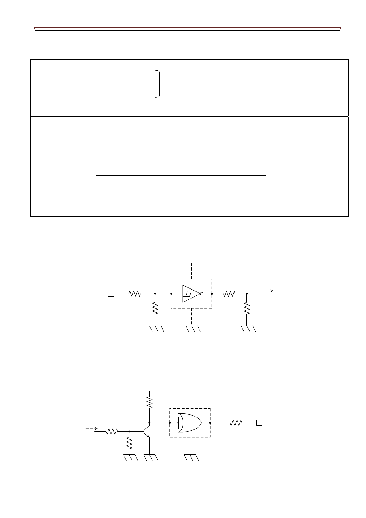
4.1.Camera Link 12226-1100-00PL(SUMITOMO3M) .................................................................................................. 7
4.2.Power LED ........................................................................................................................................................ 7
4.3.12pin Connector HR10A-7R-6PB(74) HIROSE .................................................................................................... 8
5. Timing Chart ................................................................................................................................................... 9
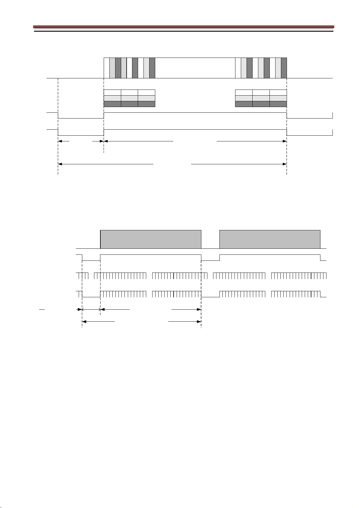
5.1.Horizontal Synchronous Signals Timing (2Tap Base Configuration ) .................................................................... 9
5.2.Vertical Synchronous Signals Timing (2Tap Base Configuration) ......................................................................... 9
5.3.Horizontal Synchronous Signals Timing (3Tap Base Configuration) ................................................................... 10
5.4.Vertical Synchronous Signals Timing (3Tap Base Configuration) ....................................................................... 10
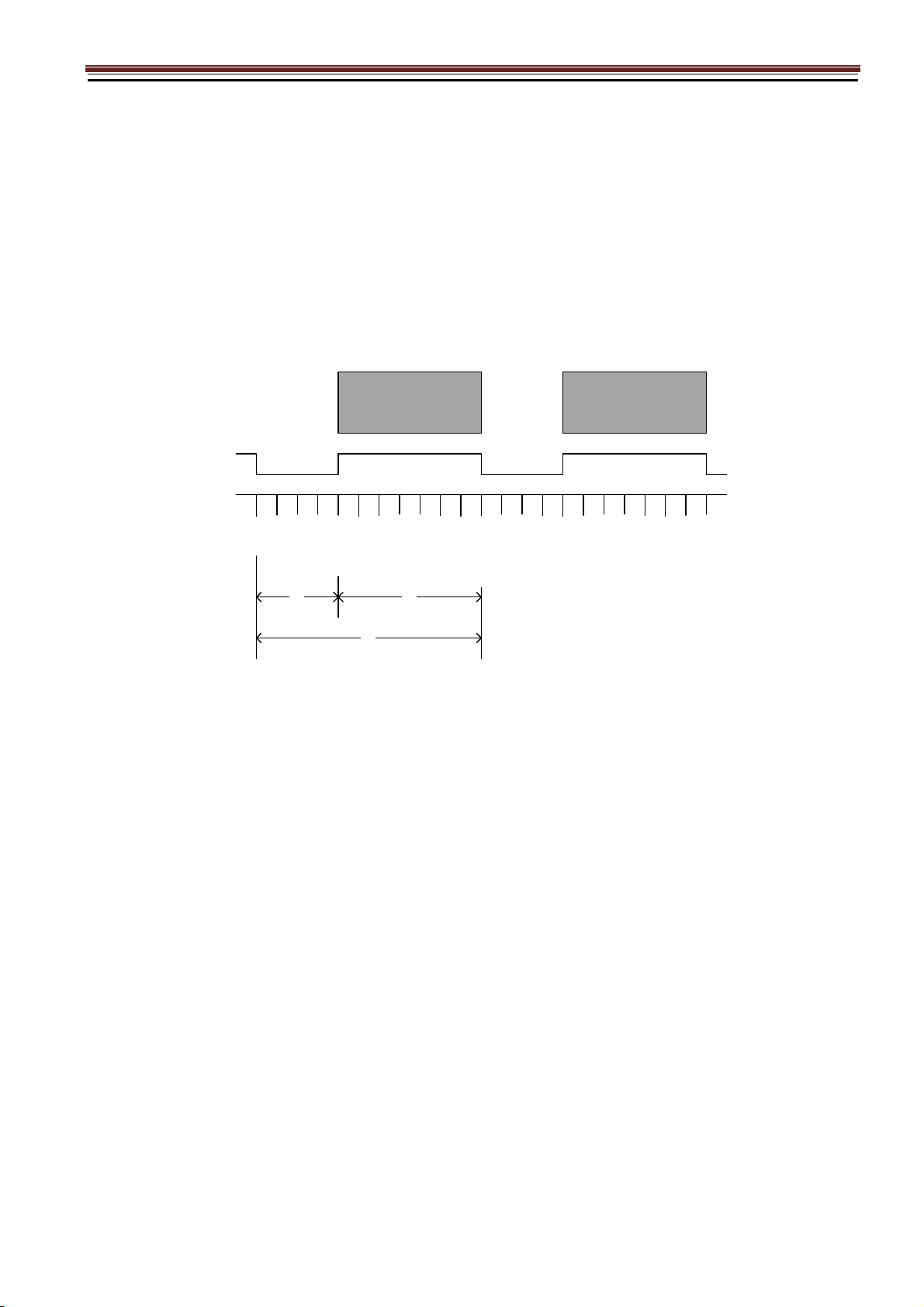
5.5.Output Format ................................................................................................................................................. 11
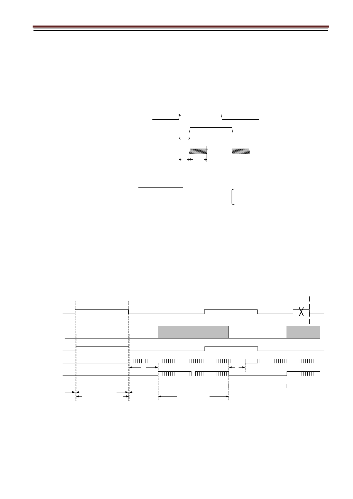
5.6.Fixed Trigger Shutter Mode .............................................................................................................................. 12
5.7.Pulse Width Trigger Shutter Mode ..................................................................................................................... 13
6. Partial Scan Mode ......................................................................................................................................... 14
7. Remote Communication ............................................................................................................................... 16
7.1.Command Specifications .................................................................................................................................. 17
7.2.Control Example .............................................................................................................................................. 21
8. Dimensions ................................................................................................................................................... 27
9. Initial Setting ................................................................................................................................................ 28
10. Cases for Indemnity (Limited Warranty) .................................................................................................... 29
11. CMOS Pixel Defect ........................................................................................................................................ 29
12. Product Support ........................................................................................................................................... 29

1. Product Outline
ID5MB-CL/ID5MC-CL is a Camera Link interfaced and 5Mega resolution camera module.
5Mega pixels CMOS sensor with diagonal length mm is utilized. Entire pixels can be read out
within 1/35.7s at 3Tap Base Configuration output.
Features
□ Global Shutter CMOS sensor is utilized.
□ Camera Link Base Configuration is supported.
□ Fixed trigger shutter mode, pulse width trigger shutter mode are operable.
□ Full frame rates are as follows.
2Tap Base Configuration
3Tap Base Configuration
32.8fps
35.7fps
8bit/10bit/12bit
8bit
2. Handling Precautions
The camera must not be used for any nuclear equipment or aerospace equipment with which mechanical
failure or malfunction could result in serious bodily injury or loss of human life. Our warranty does not apply to
dameges or defects caused by irregular and /or abnormal use of the product.
Please observe all warnings and cautions stated below.
Our warranty does not apply to damages or malfunctions caused by neglecting these precautions.
Do not use or store the camera in the following extreme conditions :
- Extremely dusty or humid places.
- Extremely hot or cold places (operating temperature -5℃ to +45℃).
- Close to generators of powerful electromagnetic radiation such as radio or TV transmitters.
- Places subject to fluorescent light reflections.
- Places subject to unstable (flickering, etc.) lighting conditions.
- Places subject to strong vibration.
· Remove dust or dirt on the surface of the lens with a blower.
· Do not apply excessive force or static electricity that could damage the camera.
· Do not shoot direct images that are extremely bright (e.g., light source, sun, etc.), and when camera is not
in use, put the lens cap on.
· Confirm the mutual ground potential carefully and then connect the camera to monitors or computers.
AC leaks from the connected devices may cause damages or destroy the camera.
· Do not apply excessive voltage. (Use only the specified voltage.) Unstable or improper power supply
voltage may cause damages or malfunction of the camera.
· The voltage ripple of camera power DC +12V±10% shall be within ±50mV. Improper power supply
voltage may cause noises on the video signals.
· The rising time of camera power supply voltage shall be less than +10V, Max 60ms. Please avoid
noises like chattering when rising.

3. Specification
3.1.General Specification
(1) Image Sensor Type Diagonal length 11.1mm Global Shutter (SONY IMX264)
Effective Pixel Number 2464(H) x 2066(V)
Cell Size 3.45μm(H) x 3.45μm(V)
Image Circle Φ11.09mm
(2) Video Output
Frequency
Pixel CLK 85MHz (2Tap) / 66MHz (3Tap)
Output effective pixel number 2464(H) x 2056(V)
2Tap Base Configuration 32.8fps 1238(H) x 2089(V) : with Blanking
3Tap Base Configuration 35.6fps 886(H) x 2089(V) : with Blanking
(3) Video Output 2Tap Base Configuration
3Tap Base Configuration
(4) Output Format Sensor AD 12bit
Camera Link 8bit / 10bit / 12bit (3Tap Base Configuration : 8bit fixed)
(5) Sensitivity B/W F11 2000lx
Color F8 2000lx
(at shutter speed 1/32.8s(OFF), Gain 0dB)
(6) Minimum
Illumination
B/W F1.4 4lx
Color F1.4 8lx
(at shutter speed 1/32.8s(OFF), Gain +12dB)
(7) Power Requirements DC+12V±10% (12pin / PoCL)
(8) Power Consumption typ 2.0 W
max 2.5 W
(9) Dimensions H:29.0mm W:29.0mm D:29.0mm excluding projection
(10) Weights Approx. 50g
(11) Lens Mount C Mount
(12) Gain 0dB ~ +12dB
(13) Shutter Speed OFF(1/32.8s) ~ 1/35000s (2Tap) / OFF(1/35.7s) ~ 1/37000s (3Tap)
(14) Trigger Mode Fixed Trigger Shutter Mode, Pulse Width Shutter Trigger Mode
(15) Partial Scan Full Frame ~ 4 Line (4Line/Step) Partial Area : 1area
(16) Safety/
Quality Standards
CE To be applied for EN55022:2006 Class B for Emission 06
To be applied for EN61000-6-2:2005 for Immunity
RoHS: Conform to RoHS
(17) Durability Vibration 20~200 Hz, 98m/s2 (10G), X,Y and Z directions (120 min for each direction)
Shock No malfunction shall be occurred with 980m/s2 (100G) for ±X,±Y,±Z, 6 directions.
(without package)
(18) Environment Operation -5℃ ~ +50℃ Humidity 0 ~ 90%RH
Storage -25℃ ~ +65℃ Humidity 0 ~ 90%RH

3.2.Camera Output Signal Specification
(1)Video Output Data Effective Video Output 2464(H) × 2056(V) (at Full Frame Scan Mode)
(2)Sync Signal Output LVAL Camera Link (LVDS)
FVAL
DVA
SP
(3)Camera Control
Signal Input
CC2・CC3・CC4 Camera Link Input(LVDS)
(4)Trigger Input Polarity Positive/Negative Selectable (Address 05)
Pulse Width 1HD(Min:14.586us) ~Approx 2 frames
CC1 Camera Link Input (LVDS) (Address 06: ⇔CN1)
(5)Serial
Communication
SerTC Camera Link (LVDS) (Serial to Camera)
SerTFG (Serial to Frame Grabber)
(6)Video Signals
White Clip Level FFEh (at Gain 0dB, 12bit)
Setup Level under 060h
Dark Shading
Both horizontal and vertical should be
under 00Fh
(7)Trigger in CN1 CN1 : 11 pin Low1.4V(max),Hi
g
h3.3V~5.0V
(8)Exposure out CN1 CN1 : 6 pin Low0.55V(max),Hi
g
h3.8V(min)
(9)FVAL out CN1 CN1 : 7 pin Low0.55V(max),Hi
g
h3.8V(min)
Trigger in CN1
Exposure / FVAL out CN1
5.0V
100Ω
SN74LVC1G14
(TI)
1.0KΩ
CN1 11pin
(Input)
Signal
2.2KΩ
2.2KΩ
Delay approx 50 ns.
5.0V
100Ω
SN74LVC1G32
(TI)
CN1 6pin,7pin
(Output)
5.0V
1KΩ
Signal
1KΩ
10KΩ
2SC4116
Delay approx 1.2μs.

3.3.Spectral Response (Representative Value)
ID5MB-CL (B/W)
ID5MC-CL (Color)

4. Connector
4.1.Camera Link 12226-1100-00PL(SUMITOMO3M)
Connector (P1)
4.2.Power LED
Camera turns on LED light, when it is supplied electricity from the frame Grabber board.
PIN
NO
PIN
NO
1 +12V(PoCL) 14 GND
2 X0- 15 X0+
3 X1- 16 X1+
4 X2- 17 X2+
5 Xclk- 18 Xclk+
6 X3- 19 X3+
7 SerTC+ 20 SerTC-
8 SerTFG- 21 SerTFG+
9 CC1- (Trigger IN -) 22 CC1+ (Trigger IN +)
10 CC2+ 23 CC2-
11 CC3- 24 CC3+
12 CC4+ 25 CC4-
13 GND 26 +12V(PoCL)

4.3.12pin Connector HR10A-7R-6PB(74) HIROSE
PIN NO
1 GND
2 Power Input (DC+12V)
3 GND
4 NC
5 GND
6 FVAL out
7 Exposure out
8 GND
9 NC
10 NC
11 Trigger in
12 GND

5. Timing Chart
5.1.Horizontal Synchronous Signals Timing (2Tap Base Configuration )
5.2.Vertical Synchronous Signals Timing (2Tap Base Configuration)
LVAL Out
~
~
Effective Data : 1232 CLK5 or 6 CLK
DVAL Out
1H = 1237 or 1238 CLK
~
~
(Camera Link Port B)
Camera Link CLK : 84.857143MHz
(Camera Link Port A) 1 3 ・・・・・・・・・・・・
5 7 2457 2459 2461 2463
1
Video Out
~
~
2
2
4
6
3
2
4
6
4
2 4 6 8 2458 2460 2462 2464
345678
2
4
6
1
2
4
6
2
2
4
5
9
2
4
6
0
2
4
5
7
2
4
5
8
(Clock count per 1frame : 2585585)
FVAL Out
1Frame = 2089H (30.47ms)
Effective Line : 2056H
DVAL Out
~
~
LVAL Out
~
~
~
~~
~
V Blanking : 33H
2
0
5
6
2
0
5
6
11
1H = 14.586 us
~
~
~
~
Video Out

5.3.Horizontal Synchronous Signals Timing (3Tap Base Configuration)
5.4.Vertical Synchronous Signals Timing (3Tap Base Configuration)
LVAL Out
~
~
Effective Data : 822 CLK63 or 64 CLK
DVAL Out
1H = 885 or 886 CLK
~
~
(Camera Link Port B)
Camera Link CLK : 66.00MHz
(Camera Link Port A) 1 4
・・・・・・・・・・・・
72458 2461 2464
1
Video Out
~
~
2 / /
2 5 8 2459 2462 /
345678
2
4
6
3
2
4
6
4
2
4
6
1
2
4
6
2
2
4
5
9
2
4
6
0
(Clock count per 1frame : 1849461)
3 6 9 2460 2463 /
2
4
5
8
(Camera Link Port C)
9
FVAL Out
1Frame = 2089H (28.02ms)
Effective Line : 2056H
DVAL Out
~
~
LVAL Out
~
~
~
~~
~
V Blanking : 33H
2
0
5
6
2
0
5
6
11
1H = 13.414 us
~
~
~
~
Video Out

5.5.Output Format
2Tap Base Configuration
ID5MB-CL ID5MC-CL
3Tap Base Configuration
ID5MB-CL ID5MC-CL
D4D3 D
2463
D
2464
・・・D2
~
~~
~
2056 Line
2464pixel
D1
~
~~
~
2056 Line
2464pixel
・・・R1 G2 R3 G4 R
2463
G
2464
D
2064
D3 / /
・・・D2
~
~~
~
2056 Line
2464pixel
D1 D6D5D4
~
~~
~
2056 Line
2464pixel
・・・R1 G2 R3 / /
G4 R5 G6 G
2464

5.6.Fixed Trigger Shutter Mode
□ This is the mode to start exposure with external input trigger signals, and set the exposure time with serial
commands.
□ Delay time (Exposure Time Delay) from detecting trigger edge in the camera to starting exposure is as below.
(1) Trigger Hsync Mode OFF : 0.15 us fixed
(2) Trigeer Hsync Mode ON : 0.15 us + max1HD
・2Tap Base Configuration 0.15us + max 1HD (14.586us)
・3Tap Base Configuration max 1HD (13.414us)
□ Triggers can be accepted even when outputting video signals.
However, trigger signals for exposure to start the next video output prior to the completion of video transmission
for the prior video output signals can not be accepted.
□ Trigger input during exposure time should be ignored. (Refer to the below A)
(Caution) Trigger Hsync Mode is available : Change the function ->SAVE->Camera restart
TRIG IN
max1HD
0.15
us
Exposure OUT
(Trigger Hsync : OFF)
0.15
us
Exposure OUT
(Trigger Hsync : ON)
Effective Line : 2056H
~
~
SP Out
(Exposure Out)
2
0
5
6
1
TRIG IN
LVAL Out
FVAL Out
Video Out
DVAL Out
~
~
1
Exposure Time
(Trigger input ignore period)
Exposure Time Delay
(A)
~
~
~
~
~
~
25H
~
~
8H

5.7.Pulse Width Trigger Shutter Mode
□ This is the mode to start exposure with external input trigger signals, and set the exposure time with
pulse width of the trigger signals.
□ Delay time (Exposure Time Delay) from detecting trigger edge in the camera to starting exposure, and from
detecting trigger end edge to completing exposure is as below.
(1) Trigger Hsync Mode OFF : 0.15 us fixed
(2) Trigeer Hsync Mode ON : 0.15 us + max1HD
・2Tap Base Configuration 0.15us + max 1HD (14.586us)
・3Tap Base Configuration max 1HD (13.414us)
□ Pulse width is min. 1HD (min) to approx. 2 frames.
Functionally, there is no upper limitation, but noises such as dark noises and shadings may be noticeable
at long time exposure.
□ Triggers can be accepted even when outputting video signals.
However, trigger signals for exposure to start the next video output prior to the completion of video transmission
for the prior video output signals can not be accepted.
(Caution) Trigger Hsync Mode is available : Change the function ->SAVE->Camera restart
TRIG IN
max1HD
0.15
us
Exposure OUT
(Trigger Hsync : OFF)
0.15
us
Exposure OUT
(Trigger Hsync : ON)
SP Out
(Exposure Out)
TRIG IN
LVAL Out
FVAL Out
Video Out
DVAL Out
Exposure Time
(Trigger input ignore period)
Exposure Time Delay Exposure Time Delay
Effective Line : 2056H
~
~
2
0
5
6
1
~
~
1
~
~
~
~
~
~
25H
~
~
8H

6. Partial Scan Mode
□ 1 partial area can be set by serial commands.
Partial Scan Setting
Partial Scan Start Position Address : 40 - 41
Partial Scan Effective Line Number Address : 50 – 51
Example
① : V Blanking : 33H fixed
② : Partial Scan Start Position : 120H
③ : Partial Scan Effective Line Number : 400H
④ : Total Lines : 433H(①+③)
FVAL
LVAL
①
④
③
Video Out
スタートポジション
②
有効ライン数
Start Position
Effective Line Number

□ When setting several partial scan areas, please set the start position and effective lines ->4 x n.
□ Total Lines
= V blanking line number (33H fixed) + Partial Scan Effective line numbers
Note that “Sum total of partial effective line numbers (expect V blanking lines) < 2056 should be met.
□ Frame Rate = 1 / Total lines
Time for 1 line = 14.586us(2Tap) / 13.414us(3Tap)
□ Example
Effective line number Total line
Frame rate
2Tap Base Configuration 3Tap Base Configuration
4H(min) 37H 1852fps 2014fps
・
12H 45H 1523fps 1656fps
・
100H 133H 515fps 560fps
・
400H 433H 158fps 172fps
・
800H 833H 82.3fps 89.4fps
・
1600H 1633H 41.9fps 45.6fps
・
2056H(max) 2089H 32.8fps 35.6fps

7. Remote Communication
Communication Settings
Baud Rate :9600bps (Initial Setting)
Data :8bit
Stop bit :1bit
Parity :None
XON / XOFF :No Control
・ Send Command Format (Host to Camera)
If send a command, set the command and parameter between STX and ETX.
STX
(02H)
Command
(2byte)
Parameter(ASCII code)
(20H-7FH)
ETX
(03H)
・ Return Command Format (Camera to Host)
Normally, a camera returns a control code which is ACK or NAK.
If return value has a text message, the message is between STX and ETX.
ACK
(06H)
・・・ Succeed
NAK
(15H)
・・・ Fail
STX
(02H)
command
(2byte)
parameter(ASCII code)
(2FH- 7FH)
ETX
(03H)
・・・ return message
・ Command list
Command Function
SR Set some values of resister
GR Get some values of resister
SU Set a user’s data
GU Get a user’s data
CS Save all configurations
CR Restore all configurations
QM Get a model name
QS Get a serial number
QV Get a firmware version
QE Get a detail of error information

7.1.Command Specifications
1) Set some values of resister
【Command】 Set : Resister
STX S R (a) (a) (d) (d) ・・・ ETX
Address Data (Variable-length :max 16 address)
【Return Value】
Succeed ・・・ ACK
Fail ・・・ NAK
2) Get some value of resister
【Command】 Get : Resister
STX G R (a) (a) (d) ETX
Address Number of data acquisition (optional)
【Return value】
Succeed ・・・ STX A R (d) (d) ・・・ ETX
Data (Data length depends on the number of acquisitions)
Fail ・・・ NAK
【Remarks】
The command gets some value of register of the specified address. The number of the acquisition is between
’0’ and ’F’( Hexadecimal ).
If appoint ’0’ at the address, the command send data of 16 address. If the command is omitted at the address,
the command send an address.
3) Set User’s data

【Command】 Set : User’s data
STX S U (n) ・・・ ETX
Table No.
User’s data (fixed length :16byte)
(0~3)
【Return Value】
Succeed ・・・ ACK
Fail ・・・ NAK
【Remarks】
The commands, sets free data on the specified register, and can use 4 tables (1 table : 16 characters).
4) Get User’s data
【Command】 Get : User’s data
STX G U 0 ETX
Table No.
(0~3)
【Response】
Succeed ・・・ STX A U (d) (d) ・・・ ETX
User’s data (fixed length : 16byte)
Fail ・・・ NAK

5) Save all configurations
【Command】 Configuration : Save
STX C S ETX
【Return Value】
Succeed ・・・ ACK
Fail ・・・ NAK
6) Restore all configurations
【Command】 Configuration : Restore
STX C R ETX
【Return Value】
Succeed ・・・ ACK
Fail ・・・ NAK
7) Get a model name
【Command】 Query : Model name
STX Q M ETX
【Return Value】
Succeed ・・・ STX R M (d) (d) ・・・ ETX
Model name (Fixed length:16byte)
Fail ・・・ NAK
8) Get a serial number
【Command】 Query : Serial number
STX Q S ETX
【Return Value】
Succeed ・・・ STX R S (d) (d) ・・・ ETX
Serial Number(Fixed length:8byte)
Fail ・・・ NAK

9) Get a firmware version
【Command】 Query : Version
STX Q V ETX
【Return Value】
Succeed ・・・ STX R V (d) (d) ・・・ ETX
Version information (fixed length:8byte)
Fail ・・・ NAK
10) Get a detail of error information
【Command】 Query : Error
STX Q E ETX
【Return Value】
Succeed ・・・ STX R E (d) (d) (d) ETX
Kind Detal
Fail ・・・ NAK
Kind Detail
0: No Error 00: Normal result
1: Communication Protocol
Error
00: The command is undefined.
01: The command length is more than defined.
02: The address is undefined.
03: The value of data is undefined.
04: The length is more than defined.
05: The table number is undefined.
06: The string of user data was abnormal.
2: Internal Control Error 00: Internal control is abnormal.
01: A read only address was written by the command.
02: A protected address was written by the command.
03: Out of range address was written by the command.
04: The selected table number is abnormal.
05: The value of the man acquisition area is abnormal.
06: A function is not implemented.
This manual suits for next models
1
Table of contents
Other iDule Digital Camera manuals

iDule
iDule ID4MUVG-CL User manual

iDule
iDule ID3MB-CL User manual

iDule
iDule ID65MB-CL User manual

iDule
iDule ID4MB-CLD User manual

iDule
iDule ID25MGB-CL User manual

iDule
iDule ID1MB 2-UCL Series User manual

iDule
iDule ID9MGB-CL User manual

iDule
iDule ID1MB-BRDC-U User manual

iDule
iDule ID4MUVG2-CL User manual

iDule
iDule ID8MUVS-CL User manual

iDule
iDule ID50MB-CL User manual

iDule
iDule ID2MB-CL User manual

iDule
iDule ID1MB-MDL-U User manual

iDule
iDule ID2MB-CLIR User manual

iDule
iDule ID50MB-OPT User manual

iDule
iDule ID4MB-CL User manual

iDule
iDule ID5MGB-CL User manual

iDule
iDule ID1MB-CL (B/W) User manual

iDule
iDule ID4MUV-CL User manual

iDule
iDule ID2MB-CLD User manual