iDule ID50MB-CL User manual

48M CMOS Camera
ID50MB-CL (B/W)
ID50MC-CL (Color)
Technical Manual
iDule Corporation

Table of Contents
PAGE
1. Product Outline ............................................................................................................................................ 3
2. Handling Precautions ................................................................................................................................... 3
3. Specification ................................................................................................................................................ 4
3.1. General Specification ..................................................................................................................................... 4
3.2. Camera Output Signal Specification ................................................................................................................. 5
3.3. Spectral Response (Representative Value) ....................................................................................................... 6
4. Connector ..................................................................................................................................................... 7
4.1. Camera Link Connector 12226-1100-00PL (3M) ............................................................................................... 7
4.2. Power LED .................................................................................................................................................... 8
4.3. 12pin Connector HR10A-10R-12PB (HIROSE) (CN1) .......................................................................................... 8
4.4. Power Select (SW1)........................................................................................................................................ 8
5. Timing Chart ................................................................................................................................................ 9
5.1. Horizontal Synchronous Signals Timing (8Tap Full Configuration) ..................................................................... 9
5.2. Vertical Synchronous Signals Timing (8Tap Full Configuration) ......................................................................... 9
5.3. Horizontal Synchronous Signals Timing (4Tap Medium Configuration) ............................................................. 10
5.4. Vertical Synchronous Signals Timing (4Tap Medium Configuration) ................................................................ 10
5.5. Image output format .................................................................................................................................... 11
5.6. Fixed Trigger Shutter Mode ........................................................................................................................... 12
5.7. Pulse Width Trigger Shutter Mode .................................................................................................................. 13
6. Partial Scan Mode ...................................................................................................................................... 14
7. Remote Communication ............................................................................................................................ 16
7.1. Command Specifications ............................................................................................................................... 17
7.2. Control Example ........................................................................................................................................... 21
8. Function Setting ......................................................................................................................................... 25
8.1. Camera function Register setting (Register setting using serial communication via microcomputer.) ............... 25
9. Dimensions................................................................................................................................................. 28
10. Initial Setting ............................................................................................................................................. 29
11. Cases for Indemnity (Limited Warranty) .................................................................................................. 30
12. CMOS Pixel Defect ..................................................................................................................................... 30
13. Product Support ......................................................................................................................................... 30

1. Product Outline
ID50MB-CL/ID50MC-CL is a Camera Link interfaced and 48M resolution camera module.
48M pixels CMOS sensor with diagonal length 45.717mm is utilized. Entire pixels can be read out
within 1/12.8s at Full Configuration output.
Features
□ Global Shutter CMOS sensor is utilized.
□ Camera Link Full Configuration is supported.
□ Fixed trigger shutter mode, pulse width trigger shutter mode are operable.
□ Full frame rates are as follows.
4Tap Medium Configuration 6.4fps :8bit / 10bit /12bit
8Tap Full Configuration 12.8fps :8bit / 10bit
【Default】 8Tap Full Configuration (12.8fps, 8bit)
2. Handling Precautions
The camera must not be used for any nuclear equipment or aerospace equipment with which mechanical
failure or malfunction could result in serious bodily injury or loss of human life. Our warranty does not apply to
dameges or defects caused by irregular and /or abnormal use of the product.
Please observe all warnings and cautions stated below.
Our warranty does not apply to damages or malfunctions caused by neglecting these precautions.
Do not use or store the camera in the following extreme conditions :
- Extremely dusty or humid places.
- Extremely hot or cold places (operating temperature -5℃ to +45℃).
- Close to generators of powerful electromagnetic radiation such as radio or TV transmitters.
- Places subject to fluorescent light reflections.
- Places subject to unstable (flickering, etc.) lighting conditions.
- Places subject to strong vibration.
· Remove dust or dirt on the surface of the lens with a blower.
· Do not apply excessive force or static electricity that could damage the camera.
· Do not shoot direct images that are extremely bright (e.g., light source, sun, etc.), and when camera is not
in use, put the lens cap on.
· Confirm the mutual ground potential carefully and then connect the camera to monitors or computers.
AC leaks from the connected devices may cause damages or destroy the camera.
· Do not apply excessive voltage. (Use only the specified voltage.) Unstable or improper power supply
voltage may cause damages or malfunction of the camera.
· The voltage ripple of camera power DC +12V±10% shall be within ±50mV. Improper power supply
voltage may cause noises on the video signals.
· The rising time of camera power supply voltage shall be less than +10V, Max 60ms. Please avoid
noises like chattering when rising.

3. Specification
3.1. General Specification
(1) Image Sensor Device type Diagonal length 45.717mm, Global Shutter type (CMOSIS CMV50000)
Effective pixel number 7920(H) x 6004(V)
36.432
27.618
45.717
(単位:mm)
Unit cell size 4.6μm(H) x 4.6μm(V)
Image circle Φ45.717mm
(2) Video Output Frequency Pixel Clock 80.5MHz
Output effective pixel number 7920(H) x 6004(V)
4Tap Medium Configuration 6.4fps 2072(H) x 6048(V) with blanking
8Tap Full Configuration 12.8fps 1036(H) x 6048(V) with blanking
(3) Video Output 4Tap Medium Configuration
8Tap Full Configuration
(4) Output Format Sensor AD 12bit
Camera Link Output
4Tap Medium Configuration :8bit / 10bit / 12bit
8Tap Full Configuration :8bit / 10bit
(5) Sensitivity B/W F11 2000lx
Color F8 2000lx
(at shutter speed 1/12.8s (OFF), Gain 0dB)
(6) Power Requirements DC+12V±10% 12 pin connector / PoCL
(7) Power Consumption typ 7.0W
(8) Dimensions H:85mm W:85mm D:60mm excluding projection
(9) Weight Approx. 500g
(10) Lens Mount M58 P:0.75 mount
(11) Gain Variable Range 0dB ~ +12dB (Guaranteed range)
(12) Shutter Speed Variable Range
4Tap Medium Configuration : OFF(1/6.4s) ~ 1/5800s
8Tap Full Configuration : OFF(1/12.8s) ~ 1/6300s
(13) Trigger Shutter Mode Fixed shutter trigger mode / Pulse width shutter trigger mode
(14) Partial Scan Full frame ~ 2Line (4Line/Step) Max 1 areas
*Start position and Effective line : Even number only
(15) Safety/Quality Standards UL : Conform to UL Standard including materials and others.
CE : To be applied for EN55022:2006 Class B for Emission06
To be applied for EN61000-6-2:2005 for Immunity
RoHS:Conform to RoHS
(16) Durability Vibration 20~200 Hz,98m/s2 (10G), X,Y and Z 3directions (120 min for each direction)
Shock No malfunction shall be occurred with 980m/s2 (100G) for ±X,±Y,and ±Z,
6 directions. (without package)
(17) Operation Environment Temperature -5 ~ +45℃
Humidity 20 ~ 80%RH with no condensation.
(18) Storage Environment Temperature -25 ~ +60℃ Humidity 20 ~ 80%RH with no condensation.

3.2. Camera Output Signal Specification
(1)Video Output Data Effective Video Output 7920(H) × 6004(V) (at Full Frame Scan Mode)
(2)Sync Signal Output
LVAL Camera Link (LVDS)
FVAL
DVAL
(3)Camera Control
Signal Input
CC2・CC3・CC4 Camera Link (LVDS) (No Function)
(4)Trigger Input Polarity Positive/Negative Selectable (Address 05h)
Pulse Width 1HD(Min) ~ Approx.2 frames
Functionally, no upper limitation is set but noises such as dark noises and
shadings might be noticeable at long time exposure.
CC1(Trigger Input) Camera Link (LVDS) (Address 06h)
12pin Connector(Trigger Input)
12pin Connector 11pin Input (LV TTL) (Trigger Input)
(5)Serial
Communication
SerTC Camera Link (LVDS) (Serial to Camera)
SerTFG (Serial to Frame Grabber)
(6)Video Signals White Clip Level
FFh
(at Gain 0dB, 8bit)
Setup Level
under
04
Dark Shading
Both horizontal and vertical should be under
04h

3.3. Spectral Response (Representative Value)
ID50MB-CL (B/W) / ID50MC-CL (Color)

4. Connector
4.1. Camera Link Connector 12226-1100-00PL (3M)
Connector (P2) Connector (P1)
PIN
NO
PIN
NO
PIN
NO
PIN
NO
1 +12V(PoCL) 14 GND
1 +12V(PoCL) 14 GND
2 Y0- 15 Y0+
2 X0- 15 X0+
3 Y1- 16 Y1+
3 X1- 16 X1+
4 Y2- 17 Y2+
4 X2- 17 X2+
5 Yclk- 18 Yclk+
5 Xclk- 18 Xclk+
6 Y3- 19 Y3+
6 X3- 19 X3+
7 100Ω 20 Terminated
7 SerTC+ 20 SerTC-
8 Z0- 21 Z0+
8 SerTFG- 21 SerTFG+
9 Z1- 22 Z1+
9 CC1- (Trigger IN -)
22 CC1+ (Trigger IN +)
10 Z2- 23 Z2+
10 CC2+ 23 CC2-
11 Zclk- 24 Zclk+
11 CC3- 24 CC3+
12 Z3- 25 Z3+
12 CC4+ 25 CC4-
13 GND 26 +12V(PoCL)
13 GND 26 +12V(PoCL)
1
14
13
26
(Base Cable Side)
(P1)
1
14
13
26
(P2)
(Full Cable Side)
(Power LED)
(SW1)
Power input
Selector switch
(CN1)
4.2. Power LED
Camera turns on LED light, when it is supplied electricity from the frame Grabber board.
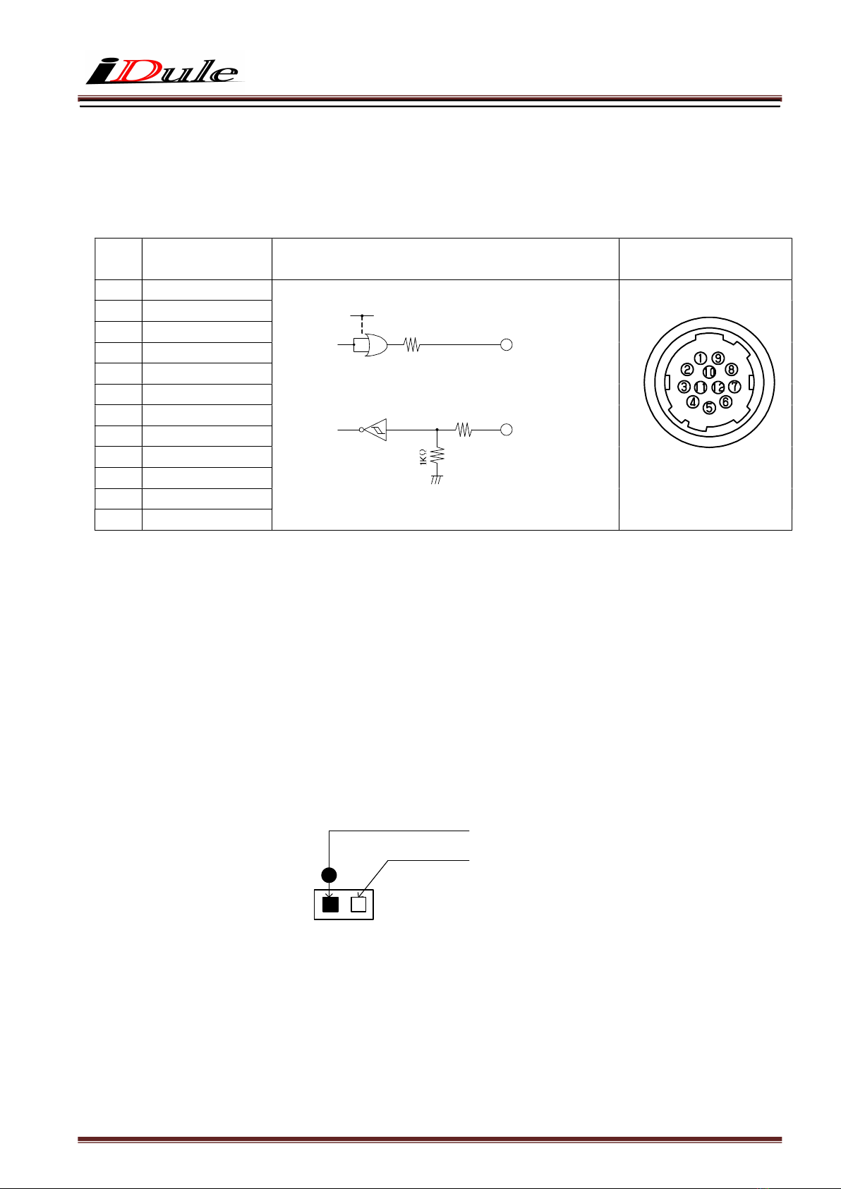
4.3. 12pin Connector HR10A-10R-12PB (HIROSE) (CN1)
4.4. Power Select (SW1)
(1) 12pin Connector (Initial Setting)
Set the switch when using non-PoCL supported frame grabber board.
Please make sure that the power of feeding side is OFF when changing the switch setting.
If the switch setting is changed while power distribution, malfunction may occur.
(2) PoCL
Set the switch when feeding power via the frame grabber board with PoCL supported.
PIN
NO IO(5V TTL)
1 GND
2 POWER IN(DC+12V)
3 GND
4 NC
5 GND
6 FVAL OUT
7 NC
8 GND
9 NC
10 NC
11 TRIGGER IN
12 GND
(SW1)
12
pin Power side
PoCL side
(CN1)
100Ω
FVAL Output
+5.0V(VCC)
External Trigger Input
SN74LVC1G32(TI)
Voh:3.8V(Min)
Vol:0.55V(Max)
SN74LVC1G14(TI)
⊿Vt-:0.71(Min)
⊿Vt+:1.04V(Max)
100Ω
11
6
12pin

5. Timing Chart
5.1. Horizontal Synchronous Signals Timing (8Tap Full Configuration)
5.2. Vertical Synchronous Signals Timing (8Tap Full Configuration)
FVAL Out
1Frame = 6048H(77.835ms)
Effective Line : 6004H
DVAL Out
~
~
LVAL Out
~
~
~
~~
~
V Blanking : 44H
6
0
0
4
6
0
0
4
1 1
1LVAL = 12.870us
~
~
~
~
Video Out
Port D
Port C
LVAL Out
~
~
Effective Data : 990 CLK46 CLK
DVAL Out
~
~
Port B ・ ・ ・ ・ ・ ・ ・ ・ ・ ・ ・ ・
Pixel
CLK : 80.5MHz
Port A
0
2
・ ・ ・ ・ ・ ・ ・ ・ ・ ・ ・ ・
1
3
・ ・ ・ ・ ・ ・ ・ ・ ・ ・ ・ ・
7912
7914
7913
7915
0 ~ 7
Video Out
~
~
7912 ~
7919
Port H
Port G
Port F ・ ・ ・ ・ ・ ・ ・ ・ ・ ・ ・ ・
Port E
4
6
5
7
7916
7918
7917
7919

5.3. Horizontal Synchronous Signals Timing (4Tap Medium Configuration)
5.4. Vertical Synchronous Signals Timing (4Tap Medium Configuration)
Port D
Port C
LVAL Out
~
~
Effective Data : 1980 CLK92 CLK
DVAL Out
~
~
Port B
・ ・ ・ ・ ・ ・ ・ ・ ・ ・ ・ ・
Pixel
CLK : 80.5MHz
Port A
0
2
・ ・ ・ ・ ・ ・ ・ ・ ・ ・ ・ ・
1
3
・ ・ ・ ・ ・ ・ ・ ・ ・ ・ ・ ・
0 ~ 7
Video Out
~
~
7912 ~
7919
・ ・ ・ ・ ・ ・ ・ ・ ・ ・ ・ ・
7916
7918
7917
7919
FVAL Out
1Frame = 6048H(155.7ms)
Effective Line : 6004H
DVAL Out
~
~
LVAL Out
~
~
~
~~
~
V Blanking : 44H
6
0
0
4
6
0
0
4
1 1
1LVAL = 25.74us
~
~
~
~
Video Out

5.5. Image output format
(1) 8Tap Full Configuration : 12.8fps
ID50MB-CL (B/W)
ID50MC-CL (Color)
(2) 4Tap Medium Configuration : 6.4fps
ID50MB-CL (B/W)
ID50MC-CL (Color)
~
~
~ ・・・
~
~
6004 Line
7920 pixel
D0 D1
8pixel
D
6
D
7
~
D
7912
D
7913
D
7918
D
7919
~
D
8
D
9
8pixel
D
14
D
15
8pixel
~
~
・・・
~
~
6004 Line
7920 pixel
8pixel 8pixel 8pixel
~
G1B0 G
7
B6 ~G
7919
B
7918
G
7913
B
7912
~
G9
B
815B14
~
~
・・・
~
~
6004 Line
7920 pixel
D0 D1
4pixel
D2 D3 D
7916
D
7917
D
7918
D
7919
4pixel
~
~
・・・
~
~
6004 Line
7920 pixel
4pixel
G1B0 G4B3 G
7919
B
7918
G
7917
B
7916

5.6. Fixed Trigger Shutter Mode
□ This is the mode to start exposure with external input trigger signals, and set the exposure time with serial
commands.
□ Delay time (Exposure Time Delay) from detecting trigger edge in the camera to starting exposure.
・4Tap Medium Configuration max 1HD (25.74us)
・8Tap Full Configuration max 1HD (12.87us)
□ Triggers can be accepted even when outputting video signals.
However, trigger signals for exposure to start the next video output prior to the completion of video transmission
for the prior video output signals can not be accepted.
□ Trigger input during exposure time should be ignored. (Refer to the below A)

5.7. Pulse Width Trigger Shutter Mode
□ This is the mode to start exposure with external input trigger signals, and set the exposure time with
pulse width of the trigger signals.
□ Delay time (Exposure Time Delay) from detecting trigger edge in the camera to starting exposure, and from
detecting trigger end edge to completing exposure.
・4Tap Medium Configuration max 1HD (25.74us)
・8Tap Full Configuration max 1HD (12.87us)
□ Pulse width is min. 1HD (min) to approx. 2 frames.
Functionally, there is no upper limitation, but noises such as dark noises and shadings may be noticeable
at long time exposure.
□ Triggers can be accepted even when outputting video signals.
However, trigger signals for exposure to start the next video output prior to the completion of video transmission
for the prior video output signals can not be accepted.
(A)
Effective Line : 6004H
(Exposure Out)
6
0
0
4
1
TRIG IN
LVAL Out
FVAL Out
Video Out
DVAL Out 6
0
0
4
1
Exposure Time
(Trigger input ignore period)
Exposure Time Delay Exposure Time Delay

6. Partial Scan Mode
□ 1 partial area can be set by serial commands.
① : 44H fixed
② : Partial Area : 20H
③ : Total Line numbers :64H (①+②)
パーシャルスキャンスタートポジション
(アドレス:40-41)
②
0
FVAL
LVAL
①
③
②
Video Out
パーシャルスキャン有効ライン数
(アドレス:50-51)
②パーシャルスキャン有効ライン数
パーシャルスキャン設定 出力画像の並び
6003
Partial Scan Setting Data sequence of output video
Partial scan effective lines
(Address
5
0
-
5
1
)
Partial scan start position
(Address 40-41)
Partial scan effective lines

□ When setting several partial scan areas, please set the start position and effective lines trying not to
overlap the areas.
□ When setting several areas, please set the areas in the numerial order of start position.
□ Entire frame line numbers = V blanking line numbers (44H fixed) + Partial effective lines
Note that “Sum total of partial effective line numbers (expect V blanking lines) < 6004” should be met.
□ Frame rate = 1 / (Entire frame line numbers × Time for 1 line)
Time of 1 line
Output mode Time of 1 line
4Tap Medium Configuration 25.74us
8Tap Full Configuration 12.87us
□ Example
Effective line
number(H)
Total line
number(H)
Frame rate(fps)
4Tap Medium 8Tap Full
mono(min) 1 45 1726.7 863.3
color(min) 2 46 1689.1 844.6
・ ・ ・ ・ ・
VGA 480 524 148.3 74.1
・ ・ ・ ・ ・
XGA 768 812 95.7 47.8
・ ・ ・ ・ ・
SXGA 1024 1068 72.8 36.4
・ ・ ・ ・ ・
UXGA 1200 1244 62.5 31.2
・ ・ ・ ・ ・
OFF(max) 6004 6048 12.8 6.4

7. Remote Communication
Via camera link cable, the camera can be controlled.
Communication Settings
Baud Rate :115200bps (fixed)
Data :8bit
Stop bit :1bit
Parity :None
XON / XOFF :No Control
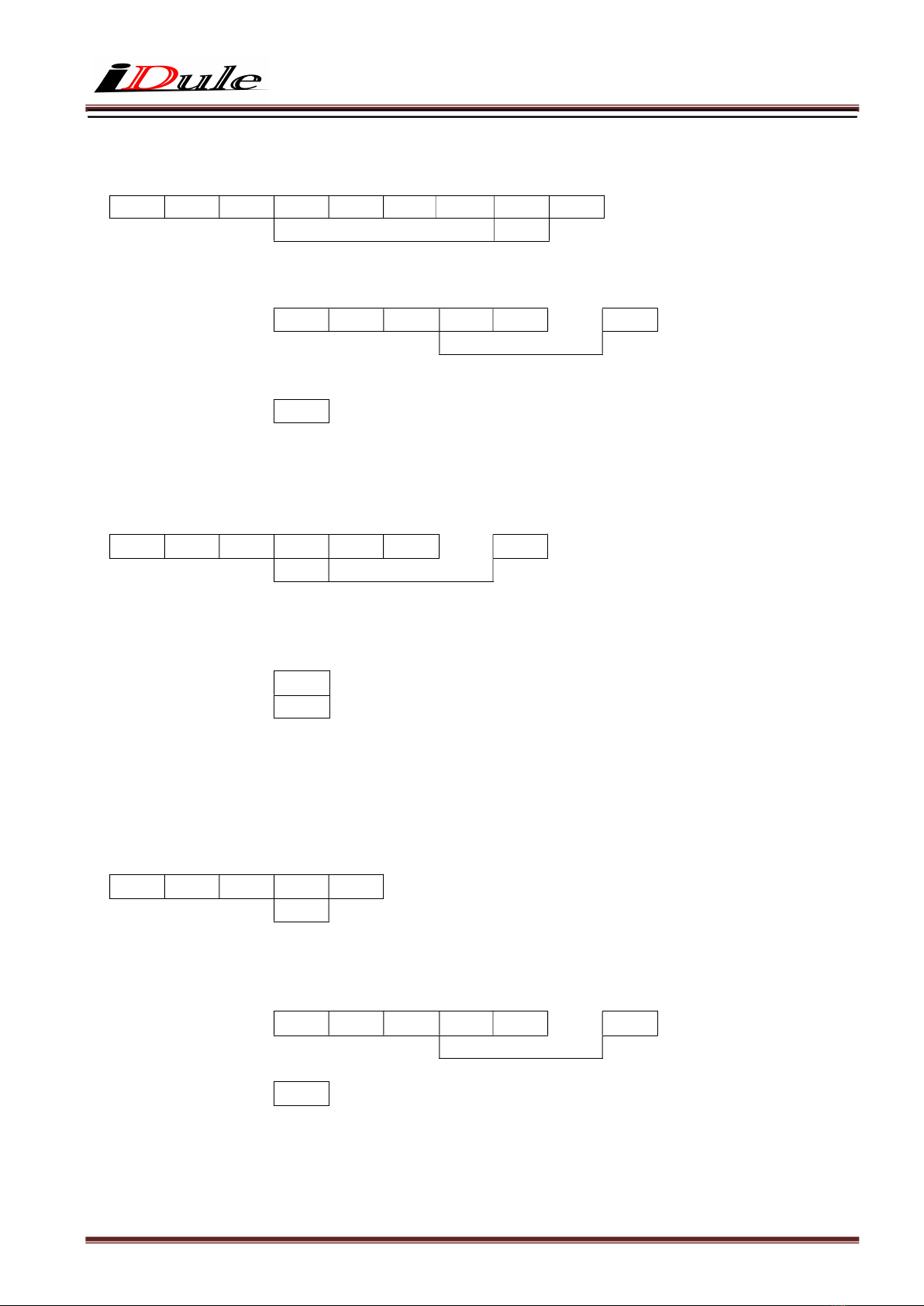
・ Send Command Format (Host to Camera)
If send a command, set the command and parameter between STX and ETX.
STX
(02H)
command
(2byte)
parameter (ASCII code)
(20H-7FH)
ETX
(03H)
・ Return Command Format (Camera to Host)
Normally, a camera returns a control code which is ACK or NAK.
If return value has a text message, the message is between STX and ETX.
ACK
(06H)
・・・ Succeed
NAK
(15H)
・・・ Fail
STX
(02H)
command
(2byte)
parameter (ASCII code)
(2FH- 7FH)
ETX
(03H)
・・・ return message
・ Command List
Command Function
SR Set some values of resister
GR Get some values of resister
SU Set a user’s data
GU Get a user’s data
CS Save all configurations
CR Restore all configurations
QM Get a model name
QS Get a serial number
QV Get a firmware version
QE Get a detail of error information
sR Dead pixel correction write area (X,Y)
gR Dead pixel correction read area (X,Y)

7.1. Command Specifications
1) Set some values of resister
【Command】 Set : Resister
STX S R (a) (a) (d) (d) ・・・ ETX
Address Data (Variable-length:max 16 address)
【Return Value】
Succeed ・・・ ACK
Fail ・・・ NAK
2) Dead pixel correction write area (X,Y)
【Command】 Set : Resister
STX s R (a) (a) (a) (a) (d) (d) ・・・ ETX
Address Data (variable length:max 16 address)
【Return Value】
Succeed ・・・ ACK
Fail ・・・ NAK
3) Get resister value
【Command】 Get : Resister
STX G R (a) (a) (d) ETX
Address Data acquisitions number
【Return value】
Succeed ・・・ STX A R (d) (d) ・・・ ETX
Data (Data length depends on the number of acquisitions)
Fail ・・・ NAK
【Remarks】
The command gets some value of register of the specified address. The number of the acquisition is between
’0’ and ’F’( Hexadecimal ).
If appoint ’0’ at the address, the command send data of 16 address. If the command is omitted at the address,
the command send an address.
4) Dead pixel correction read area (X,Y)
【Command】 Get : Resister
STX g R (a) (a) (a) (a) (d) ETX
Address Data acquisitions number
【Return Value】
Succeed ・・・ STX A R (d) (d) ・・・ ETX
Data(Data length depends on the number of
acquisitions)
Fail ・・・ NAK
5) Set User’s data
【Command】 Set : User’s data
STX S U (n) ・・・ ETX
Table No. User’s data (fixed length :16byte)
(0~3)
【Return Value】
Succeed ・・・ ACK
Fail ・・・ NAK
【Remarks】
The commands, sets free data on the specified register, and can use 4 tables (1 table : 16 characters).
6) Get User’s data
【Command】 Get : User’s data
STX G U 0 ETX
Table No.
(0~3)
【Response】
Succeed ・・・ STX A U (d) (d) ・・・ ETX
User’s data (fixed length : 16byte)
Fail ・・・ NAK

7) Save all configurations
【Command】 Configuration : Save
STX C S ETX
【Return Value】
Succeed ・・・ ACK
Fail ・・・ NAK
8) Restore all configurations
【Command】 Configuration : Restore
STX C R ETX
【Return Value】
Succeed ・・・ ACK
Fail ・・・ NAK
9) Get a model name
【Command】 Query : Model name
STX Q M ETX
【Return Value】
Succeed ・・・ STX R M (d) (d) ・・・ ETX
Model name (Fixed length:16byte)
Fail ・・・ NAK
10) Get a serial number
【Command】 Query : Serial number
STX Q S ETX
【Return Value】
Succeed ・・・ STX R S (d) (d) ・・・ ETX
Serial Number(Fixed length:8byte)
Fail ・・・ NAK

11) Get a firmware version
【Command】 Query : Version
STX Q V ETX
【Return Value】
Succeed ・・・ STX R V (d) (d) ・・・ ETX
Version information (fixed length:8byte)
Fail ・・・ NAK
12) Get a detail of error information
【Command】 Query : Error
STX Q E ETX
【Return Value】
Succeed ・・・ STX R E (d) (d) (d) ETX
Kind
Detal
Fail ・・・ NAK
Kind Detail
0: No Error 00: Normal result
1: Communication Protocol
Error
00: The command is undefined.
01: The command length is more than defined.
02: The address is undefined.
03: The value of data is undefined.
04: The length is more than defined.
05: The table number is undefined.
06: The string of user data was abnormal.
2: Internal Control Error 00: Internal control is abnormal.
01: A read only address was written by the command.
02: A protected address was written by the command.
03: Out of range address was written by the command.
04: The selected table number is abnormal.
05: The value of the man acquisition area is abnormal.
06: A function is not implemented.
This manual suits for next models
1
Table of contents
Other iDule Digital Camera manuals

iDule
iDule ID9MGB-CL User manual

iDule
iDule ID2MB-CLD User manual

iDule
iDule ID1MB-BRDCS-U User manual

iDule
iDule ID5MGB-CL User manual

iDule
iDule ID25MB-CL User manual

iDule
iDule ID1MB-MDL-U User manual

iDule
iDule ID4MB-CLD User manual

iDule
iDule ID4MB-CL User manual

iDule
iDule ID3MB-CL User manual

iDule
iDule ID50MB-OPT User manual

iDule
iDule ID4MUVG2-CL User manual

iDule
iDule ID5MB-CL User manual

iDule
iDule ID4MUV-CL User manual

iDule
iDule ID2MB-CLIR User manual

iDule
iDule ID2MB-CL User manual

iDule
iDule ID1MB-BRDC-U User manual
 User manual")
iDule
iDule ID1MB-CL (B/W) User manual

iDule
iDule ID1MB 2-UCL Series User manual

iDule
iDule ID4MUVG-CL User manual

iDule
iDule ID65MB-CL User manual


