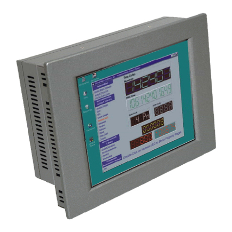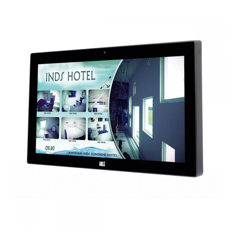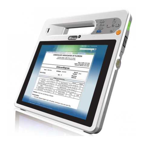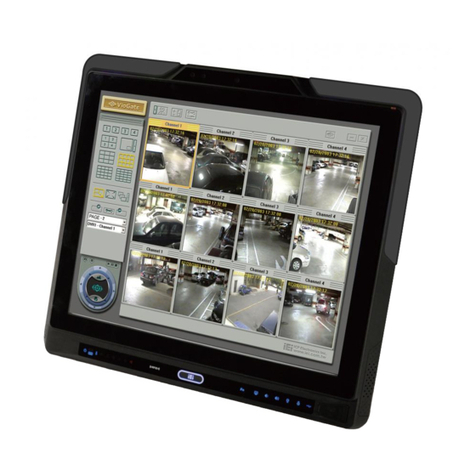
PPC-37xxA-N26 Panel PC
Page vi
5.1 INTRODUCTION......................................................................................................... 61
5.1.1 Starting Setup................................................................................................... 61
5.1.2 Using Setup...................................................................................................... 61
5.1.3 Getting Help..................................................................................................... 62
5.1.4 Unable to Reboot after Configuration Changes.............................................. 62
5.1.5 BIOS Menu Bar................................................................................................ 62
5.2 MAIN........................................................................................................................ 63
5.3ADVANCED............................................................................................................... 64
5.3.1 ACPI Settings................................................................................................... 64
5.3.2 RTC Wake Settings........................................................................................... 65
5.3.3 CPU Configuration.......................................................................................... 67
5.3.4 IDE Configuration........................................................................................... 68
5.3.5 USB Configuration........................................................................................... 69
5.3.6 F81866 Super IO Configuration...................................................................... 72
5.3.6.1 Serial Port n Configuration....................................................................... 72
5.3.7 F81866 H/W Monitor....................................................................................... 76
5.3.7.1 Smart Fan Mode Configuration................................................................ 78
5.3.8 Serial Port Console Redirection ...................................................................... 79
5.3.8.1 Console Redirection Settings.................................................................... 79
5.3.9 iEi Feature ....................................................................................................... 82
5.4 CHIPSET ................................................................................................................... 83
5.4.1 Host Bridge Configuration .............................................................................. 84
5.4.1.1 Intel IGD Configuration............................................................................ 84
5.4.2 South Bridge Configuration............................................................................. 85
5.5 BOOT........................................................................................................................ 86
5.6 SECURITY................................................................................................................. 88
5.7 SAVE &EXIT............................................................................................................ 88
6 DRIVER INSTALLATION......................................................................................... 90
6.1AVAILABLE SOFTWARE DRIVERS .............................................................................. 91
6.2 STARTING THE DRIVER PROGRAM ............................................................................ 91
6.3 CHIPSET DRIVER INSTALLATION............................................................................... 92
6.4 VGADRIVER INSTALLATION.................................................................................... 96
6.5 LAN DRIVER INSTALLATION.................................................................................. 100
6.6AUDIO DRIVER INSTALLATION ............................................................................... 102
