IEM Tel-O-Graph BT User manual

Technical Manual
EN

2
Technical Manual
Tel-O-Graph® BT, Tel-O-Graph® BT plus, Tel-O-Graph® GSM, Tel-O-
Graph® GSM plus
IEM GmbH
Gewerbepark Brand 42
52078 Aachen
Germany
E-Mail:
Website:
www.iem.de
The contents of this technical manual must not be duplicated or published without the written
authorization of IEM GmbH.
The copyright for the components used in these products remains with the manufacturer of this device.
Any attempt will be prosecuted.
© IEM GmbH 2022. All Rights reserved.
Version 3.0 - 03/2022 - EN

Introduction
3
Table of contents
1Introduction ..................................................................................................................................................5
1.1 About IEM GmbH........................................................................................................................................5
1.2 Target audience ..........................................................................................................................................5
1.3 Using the technical manual ......................................................................................................................5
2Product description.....................................................................................................................................6
2.1 Intended Use................................................................................................................................................6
2.1.1 Tel-O-Graph® BT and Tel-O-Graph® BT plus ...................................................................................6
2.1.2 Tel-O-Graph®GSM and Tel-O-Graph®GSM plus..............................................................................6
2.2 Method..........................................................................................................................................................6
2.2.1 Oscillometric analysis of blood pressure ..........................................................................................6
2.2.2 Pulse Wave Analysis..............................................................................................................................7
2.3 Regulatory standards.................................................................................................................................7
2.4 The device ....................................................................................................................................................8
2.4.1 Views ........................................................................................................................................................8
2.4.2 Label .........................................................................................................................................................9
2.4.3 Button functions.................................................................................................................................. 10
2.5 Power Supply............................................................................................................................................ 11
2.6 Technical data (latest version).............................................................................................................. 11
3Service Software....................................................................................................................................... 13
3.1 Preconditions............................................................................................................................................ 13
3.1.1 Operating system ................................................................................................................................ 13
3.1.2 Equipment ............................................................................................................................................ 13
3.2 Installation and First Start...................................................................................................................... 13
3.3 General....................................................................................................................................................... 13
3.3.1 Topbar ................................................................................................................................................... 14
3.3.2 Bottom Bar ........................................................................................................................................... 14
3.3.3 Log Window.......................................................................................................................................... 14
3.3.5 Working area ........................................................................................................................................ 15
3.4 Functions................................................................................................................................................... 15
3.4.2 Device Tests......................................................................................................................................... 16
3.4.3 Time / Date........................................................................................................................................... 16
3.4.5 Serial /Board Number......................................................................................................................... 17
3.4.6 Measurements..................................................................................................................................... 17
3.4.7 Errors ..................................................................................................................................................... 17
3.4.9 PWA Keys ............................................................................................................................................. 18
3.4.10 Com-Module Board Number ........................................................................................................ 18
3.4.11 Service Date..................................................................................................................................... 18

4
3.4.12 Firmware .......................................................................................................................................... 19
3.5 Error handling ........................................................................................................................................... 19
3.5.1 Error output in the logging area........................................................................................................ 19
3.5.2 Error output in the Windows notifications...................................................................................... 19
4Calibration control.................................................................................................................................... 20
5Repairing .................................................................................................................................................... 21
5.1 Responsibilities ........................................................................................................................................ 21
5.2 Disassembling the Tel-O-Graph®blood pressure monitors ............................................................ 21
5.2.1 Tel-O-Graph®BT and Tel-O-Graph®BT plus .................................................................................. 21
5.2.2 Tel-O-Graph®GSM and Tel-O-Graph®GSM plus........................................................................... 22
5.3 Modules and components that can be replaced by trained and authorized individuals............ 22
5.3.1 Main Board ........................................................................................................................................... 22
5.3.2 Pump ..................................................................................................................................................... 23
5.3.3 Silicone Connector.............................................................................................................................. 24
5.3.4 Cuff connector..................................................................................................................................... 24
5.3.5 Valve ...................................................................................................................................................... 25
5.3.6 Battery contacts .................................................................................................................................. 25
5.3.7 LC-Display............................................................................................................................................. 26
5.3.8 Bluetooth board ................................................................................................................................... 26
5.3.9 GSM board............................................................................................................................................ 27
5.3.10 Stripline antenna............................................................................................................................. 28
5.3.12 Button ............................................................................................................................................... 29
5.3.13 SIM card ........................................................................................................................................... 29
5.3.14 Lower housing................................................................................................................................. 29
5.4 Checking the accessories ...................................................................................................................... 30
5.4.1 Cuff control........................................................................................................................................... 30
5.4.2 Battery control ..................................................................................................................................... 30
5.5 Solutions to known problems................................................................................................................ 31
5.5.1 Board reset ........................................................................................................................................... 31
6Description of Errors................................................................................................................................ 32
6.1 Measurement Failures (Error) ............................................................................................................... 32
6.2 Transmission Failures (Code) ............................................................................................................... 36
7Replaceable components ....................................................................................................................... 40

Introduction
5
1Introduction
This technical manual provides technical information on the Tel-O-Graph®upper-arm blood pressure
monitor with its models Tel-O-Graph®BT, Tel-O-Graph®BT plus, Tel-O-Graph®GSM and Tel-O-Graph®
GSM plus. Please refer to the Tel-O-Graph®Instructions for Use (IfU) when using this technical manual.
1.1 About IEM GmbH
IEM GmbH is a German manufacturer of compact, high-technological medical equipment in the non-
invasive bio-sensory field. The company was established in October 1993 achieving innovative, cost-
efficient solutions for the public and private health sectors. IEM has a selection of highly qualified
engineers devoted to research and development, providing a high level of technical support and training
to our partners worldwide. The Quality Management System of IEM is certified to EN ISO 9001:2015, EN
ISO 13485:2016 and meets 21 CFR 820 (US-QSR).
1.2 Target audience
Users of this technical manual are expected to be familiar with the standard medical and electronic
terms and practices. The technical manual is designed to enable authorized service technicians or
distributors to repair and maintain the Tel-O-Graph®models.
1.3 Using the technical manual
This technical manual provides technical information on the Tel-O-Graph®. Read through this technical
manual carefully. If there is an unexpected problem with a device that cannot be solved with the help
and information in this manual, please contact IEM and provide the following information (according to
the quality agreement):
1. Date of occurrence of the suspected incident
2. Country of occurrence
3. Gender and age of the patient
4. Type of the concerned product (according to label)
5. The serial number or batch number of the concerned product
6. Any error code or description necessary to understand the circumstances of the suspected
incident, including photos as necessary
7. Any peripheral device(s) used with the Product during the suspected incident

6
2Product description
The Tel-O-Graph®is a fully automatic upper-arm blood pressure and pulse monitor, using the
oscillometric method to measure and calculate the blood pressure and pulse of a patient. The
Tel-O-Graph®family consists of four different models, all being used primarily for telemetric blood
pressure monitoring. In particular, the different models are:
•Tel-O-Graph®BT
•Tel-O-Graph®BT plus
•Tel-O-Graph®GSM
•Tel-O-Graph®GSM plus
All models have in common that the recorded blood pressure and pulse data can be transferred via
communication networks. At the models, Tel-O-Graph®BT and Tel-O-Graph®BT plus the recorded data
is transmitted via a Bluetooth®interface to an appropriate Bluetooth®counterpart connected to a preset
recipient, while the Tel-O-Graph®GSM and Tel-O-Graph®GSM plus use a mobile communication
network for direct data transmission. The models that have a plus in their name provide the option of
recording data for pulse wave analysis in addition to blood pressure measurement.
2.1 Intended Use
2.1.1 Tel-O-Graph® BT and Tel-O-Graph® BT plus
The Tel-O-Graph®BT is intended for the measurement of blood pressure and pulse on the upper arm in
adults. The blood pressure monitor is suitable for individuals with an arm circumference of 20-55 cm
(7.9-21.7 in) when used with the corresponding monitor cuff size.
The data measured is automatically transmitted.
The Tel-O-Graph®BT with PWA-license additionally records pulse waveform data.
2.1.2 Tel-O-Graph®GSM and Tel-O-Graph®GSM plus
The Tel-O-Graph®GSM is intended for the measurement of blood pressure and pulse on the upper arm
in adults. The blood pressure monitor is suitable for individuals with an arm circumference of 20-55 cm
(7.9-21.7 in) when used with the corresponding monitor cuff size.
The data measured is automatically transmitted.
The Tel-O-Graph®GSM with PWA-license additionally records pulse waveform data.
This product can be used as a component in a telemetry application. IEM GmbH hereby informs you
that complete and correct data transmitted in a telemetry application requires the use of services,
performance characteristics, and infrastructure (hereinafter referred to as “Services”) provided by third
parties such as telecommunication companies.
IEM GmbH cannot guarantee in any form the timely and local availability of such “Services”, nor, as a
result, the availability of data received and transmitted using the product.
2.2 Method
According to the type of the Tel-O-Graph®two methods are used to determine the patient’s values.
2.2.1 Oscillometric analysis of blood pressure
The oscillometric technique monitors the differences in cuff pressure caused by blood flowing through
the brachial artery. No Korotkoff sounds are monitored.
The oscillometric method has several advantages:
•No microphone used
•Easy to fit the cuff
•Fast BP measurement
•No noise artifacts

Product description
7
The disadvantage of the oscillometric method is the sensitivity to movement.
Measurement Cycle
The oscillometric method can be divided into three measurement steps (see Fig. 1):
1. Cuff inflation
The cuff is pumped up to a certain predefined pressure that is high enough to
cut off the arterial blood flow in the arm.
2. Cuff deflation
The cuff pressure is reduced in steps at a controlled rate (actual BP
measurement). As the pressure is reduced, the blood begins to flow through
the artery. The amplitude of the oscillations in the cuff begins to increase
until a maximum amplitude is reached, after which the amplitude decreases
as cuff pressure is reduced. The highest pulse amplitude is referred to as
MAP (Mean Arterial Pressure). The systolic and diastolic values are indirectly
determined by a complex software algorithm.
3. Rapid cuff
deflation
The remaining pressure in the cuff is reduced to zero rapidly.
Figure 1: Cuff pressure and pulse amplitude vs. time
Auto feedback logic (AFL)
Based on the last BP measurement, the maximum inflation pressure of
the next BP measurement targets a few mmHg above the last systolic
BP. This minimizes the patient’s discomfort.
Rapid Stepwise Deflation
The Tel-O-Graph®has built-in rapid stepwise deflation to minimize the
patient’s discomfort.
2.2.2 Pulse Wave Analysis
In addition to the usual blood pressure and pulse monitoring, both the Tel-O-Graph®BT plus and Tel-O-
Graph®GSM plus record the pulse waveform of the pulse and transmit this information alongside the
blood pressure.
2.3 Regulatory standards
The Tel-O-Graph®product family fulfills the following regulatory standards:
8
•Directive 93/42/EEC (MDD)
•Directive 2014/53/EU (RED)
•Directive 2011/65/EU (RoHS)
•IEC 60601-1: 2012, IEC 60601-1-2: 2014, IEC 60601-1-6: 2013, IEC 60601-1-11: 2015
•IEC 80601-2-30: 2013
•FCC 47 CFR Part 15
•ETSI EN 301 489-1 V2.1.1 (2017-02)
•ETSI EN 301 489-17 V3.1.1 (2017-02)
•IEEE/ANSI C63.27-2017
•FDA 510 (K) (only without PWA option)
2.4 The device
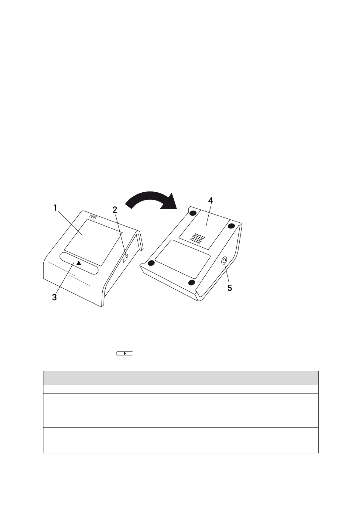
2.4.1 Views
Figure 2: Top and bottom part of the device
1
Display
4
Battery cover
2
Infrared interface (for service)
5
Air tube socket
3
Operating button ( )
View
Included elements
Top Side
The top of the recorder includes the operating button and the display
Bottom Side
The bottom side of the recorder includes the battery compartment protected by the
battery cover and the label to identify the device’s serial number, IEM’s service
address, and the CE mark (detailed explanation of the information on the label in
chapter 2.4.2).
Left Side
The left side of the housing includes the air tube socket.
Right Side
The right side of the housing includes an IR port for communication via IR interface,
which is used only for service purposes.
Product description
9
2.4.2 Label
The following label is given as an example to explain all relevant contained information for the revision
procedure:
Figure 3: Sample label (Tel-O-Graph®BT plus)
The replacement of some components requires the renewal of the label. The corresponding label must
be requested at IEM. All relevant information must be available for this purpose. The replacement of the
following components is affected:
•Communication board (Bluetooth and GSM)
•Lower housing
•SIM card
Explanation of relevant information
Category
Symbol
Meaning
Communication
module
Designation of the FCC radio authorization of the assembled
communication module
This product has a module to communicate via Bluetooth®interface.
This product has a module to communicate via a global system for
mobile communication.
BT ID
Bluetooth®module-specific identifier (MAC address)
IMEI
GSM module-specific identifier

10
Category
Symbol
Meaning
ICCID
SIM card-specific identifier
Device-specific
identifier
Serial number
AN
Article number
Name
BT
Measurements: blood pressure
Communication: via Bluetooth®
BT plus
Measurements: blood pressure and PWA
Communication: via Bluetooth®
GSM
Measurements: blood pressure
Communication: via GSM
GSM plus
Measurements: blood pressure and PWA
Communication: via GSM
2.4.3 Button functions
The Tel-O-Graph®has just one operating button: . This button can be used to activate
single actions.
Function
Instruction
Turning the
recorder on
Pressing the operating button turns the recorder on. When the recorder is turned
on, the following is displayed:
Figure 4: Home screen
The recorder turns off automatically after 5 minutes without any operation.
Starting a single
measurement
Pressing the operating button after the recorder has been turned on starts a
single blood pressure measurement. The recorder performs a blood pressure
measurement according to the measurement cycle.
Canceling a
measurement
A blood pressure measurement can be canceled by pressing the operating
button at any time. The remaining pressure in the cuff is reduced to zero rapidly.

Product description
11
Opening the
recorder’s menu
(BT)
Tel-O-Graph®BT / BT plus
Press and hold the operating button for at least 6 seconds. The individual menu
options will be displayed. After 3 seconds, the display will show “bt”. Ignore this
and hold down the button for another 3 seconds.
After 6 seconds, the menu automatically opens and the display will
automatically show the following menu items:
▪Passive pairing (PAI P)
▪Infrared transmission (Ir)
▪Active pairing (PAI A)
▪Bluetooth®transmission (bt)
▪Delete measured values (c lr)
Opening the
recorder’s menu
(GSM)
Tel-O-Graph®GSM / GSM plus
Press and hold the operating button for at least 3 seconds. The individual menu
options will be displayed and will automatically show the following menu items:
▪Mobile network transmission (IP)
▪Infrared transmission (Ir)
Delete measured values (c lr)
2.5 Power Supply
Each Tel-O-Graph®model can be used with 4 Alkaline batteries (NiMH or LR6, AA). If a device is not
used for longer periods, remove the batteries from the device to avoid possible battery leakage damage.
We recommend using high quality batteries for optimal performance.
All devices have an additional memory battery (internal Lithium-cell CR2032). It should be replaced after
2 years during the regular inspection. If a device is not in use, power consumption under standby-
conditions yields 2.5 years life for this battery and 5.9 years when regularly operated.
If a user presses the operating button, the device will power up from Off-mode into stand-by. The device
will automatically power down if not used for approximately five minutes. Immediately after the
measurement, it is stored in the non-volatile memory. In case of sudden power loss, the device triggers
the safe operating state.
2.6 Technical data (latest version)
General Performance
Specification
Value
Unit
Measuring method
Oscillometric
Blood pressure measurement
range
Systolic
Diastolic
60 to 290
30 to 195
mmHg
Pulse measurement range
30 to 240
1/min
Pressure accuracy
± 2 % or ± 3 mmHg, whichever is greater
Memory (without PWA)
350
measurements
Memory (with PWA)
15
measurements
Power supply
4 - 6 VDC (4 x NiMH or LR6, AA)
Battery capacity
Ca. 500*
measurements
Dimensions (L x W x H)
151 x 108 x 57
mm

12
Weight (excluding batteries)
Tel-O-Graph®BT (plus): 334
g
Tel-O-Graph®GSM (plus): 344
Material
ABS (acrylonitrile-butadiene-styrene)
Operating temperature
+ 5 to + 40
°C
Transport temperature
- 25 to + 70
°C
Storage temperature
- 25 to + 70
°C
Ambient pressure
700 to 1060
hPa
Rel. air humidity, not condensing
(operation, transport, and
storage)
15 to 93
%
*in the case of 2 measurements per day with quality batteries (alkaline)
Wireless Performance
Property
Description
General
Data transfer identification
Serial number
Infrared
Infrared transceiver
Range up to 1.5 meters
Bluetooth
wt11i / wt11u
Bluetooth Chip
Silicon Labs WT11i / WT11u
Bluetooth Version
Bluetooth v2.1 + EDR (Enhanced Data Rate)
Transmission output
power
Bluetooth class 1 radio (TX power: 17 dBm)
BT121
Bluetooth Chip
Silicon Labs BT121-A
Bluetooth Version
Bluetooth 4.1 Dual Mode compliant
Transmission output
power
Bluetooth class 1 radio (TX power: 12 dBm with Bluetooth BR/EDR)
GSM
GSM Chip
Cinterion EHS6
Frequency bands
GSM/GPRS/EDGE: Quad band 850/900/1800/1900MHz
UMTS/HSPA+: Five band 800/850/900/1900/2100MHz
Transmission output power
Class 1, 3, 4 and E2 (2 W) for 800MHz and 2100MHz
Internet Access
The default for APN, User, Password, and DNS released by IEM
Service Software
13
3Service Software
The Service Software “IEM Service” is intended to be used for revisioning work e.g. functional tests, failure
analysis, and hardware identification.
3.1 Preconditions
3.1.1 Operating system
The software is released by IEM for the following operating systems: Windows®10, Windows®11
Minimal graphic resolution: 1600 x 900 pixel
3.1.2 Equipment
-Irdroid USB irDA Transceiver (Infrared dongle) with a USB extension
3.2 Installation and First Start
Run the setup.exe file and follow the instructions. During the installation process, the security certificate
is checked. The "IEM Service" application can then be launched from the Start menu.
The software is protected against misuse by third parties through the use of a personal account. Before
using the software for the first time, this account must be created. For this purpose, a one-time login
provided by IEM is used when starting the software for the first time. After entering the data correctly, the
mask for entering the account information is displayed. The newly set password must be repeated. The
input of the username is limited to max. 12 characters, the input of the password is limited to 20
characters.
If you have lost your access data, please contact IEM technical support.
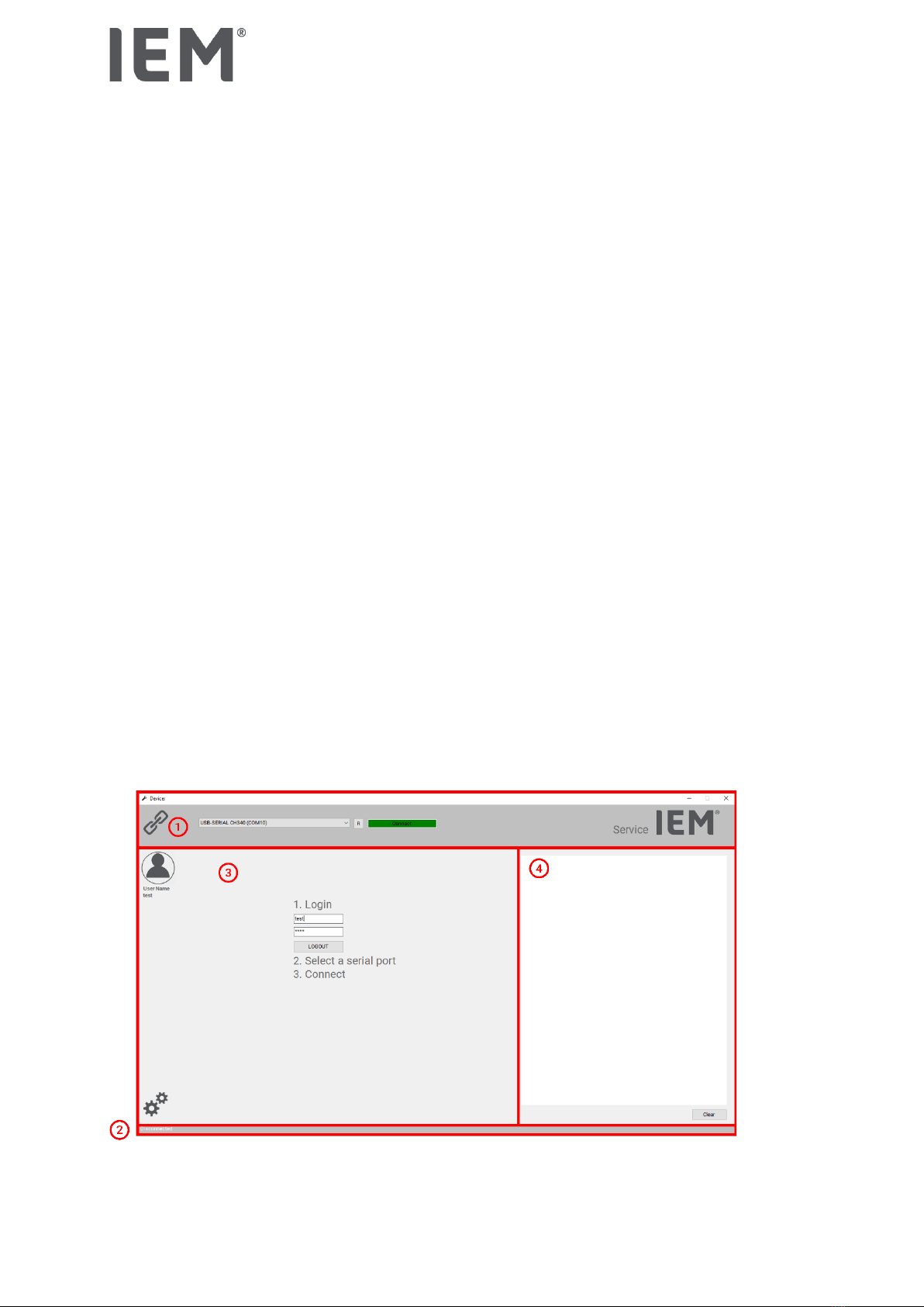
3.3 General
The following image shows an example view for the main window of the software. The individual areas
are then explained in more detail.
Figure 5: Main Window separated into functional parts
1 Top bar 2 Bottom bar 3 Actions 4 Logging

Technical Manual
EN
3.3.1 Topbar
Device
The window title shows the currently connected device type including the firmware version.
Connection
There is a drop-down menu for selecting the COM port via which the interface is connected. All COM ports
that are currently declared as "active" by the operating system are listed here. After selecting the COM
port, the connection can be established via the "Connect" button. If the connection is successful, the name
of the button changes to "Disconnect". The connection can now be disconnected again via the same
button. A connection can only be established after successful login.
If a new device is to be used with the software, it is important to disconnect the interface beforehand and
reconnect it with the new device. This is the only way to ensure that the functions suitable for the currently
connected device are made available.
About window
Clicking on the IEM logo gives information about the software version and the manufacturer.
3.3.2 Bottom Bar
The current connection status is displayed in the footer. If a device is connected, "Connect" is displayed
and the bar is colored green. If the device has been disconnected, the status changes to "Disconnected"
and the color changes to gray.
3.3.3 Log Window
A logging area is permanently visible in the right part of the main window. In this area, the results of the
executed actions are documented.
In the following picture an example log for reading the time and date can be seen (Figure 6).
Figure 6: Example of log area (Read time/date)
-A connection test is performed before each action that is executed.
-Logging entries for actions that send a command to the connected device begin with ">".
-Logging entries for actions that send information from the device to the software start with "<".
The history can be cleared with the “Clear” button below.
Since several attempts may be made during the execution of an action, errors may be displayed in the
log, but they are independent of the final result. As long as the final log entry confirms a successful
execution, such preceding log entries that indicate an error are irrelevant.

Service Software
15
3.3.5 Working area
As long as the user has not yet logged in, the area contains the mask for the login. The login is performed
using the username and password pair generated during the first-time login. If the login was successful,
the button for establishing a connection in the top bar changes color from red to green and the username
used appears below the user pictogram on the left edge.
After a connection has been successfully established, the content of the area changes and the device
actions available for the connected device is displayed. The explanation of the individual actions follows
in Chapter 3.4.
3.4 Functions
The following picture shows the workspace when all actions available for the Tel-O-Graph®are available.
Depending on the firmware of the device, some functions are not available. These functions are then
displayed grayed out.
Figure 7: Work area with all available functions for the Tel-O-Graph®

16
3.4.2 Device Tests
Button name
Assigned action
Beep
Sends a command to trigger the beeper.
A single beep should be heard.
Battery Voltage
Sends a command to read out the voltage applied by the inserted batteries.
The voltage read is displayed in millivolts.
Memo Voltage
Sends a command to read out the voltage applied by the inserted memory
button cell.
The voltage read is displayed in millivolts.
Test EEPROM
Sends a command to check the performance of the memory. Certain areas
of the memory are written with defined values and read out again. This
action takes about 20 minutes.
A confirmation window appears: Deleting all stored measurements has to
be confirmed.
The result of the test is displayed.
3.4.3 Time / Date
Button name
Assigned action
Read
Sends a command to read the time and date set in the device.
The set time and date are displayed in the following format:
YYYY/MM/DD, hh:mm:ss (UTC+0 is the correct setting)
Set
Sends a command to set the time and date in the device.
A confirmation window appears: Setting the time to UTC+0 has to be
confirmed.
The set time and date are displayed.

Service Software
17
3.4.5 Serial /Board Number
Button name
Assigned action
Read Serial Number
Sends a command to read the serial number set in the device.
The read serial number is displayed.
Read Board Number
Sends a command to read the mainboard number assembled in the device.
The number of the assembled mainboard is displayed.
Replace Main-Board
Number
Sends commands to read out needed information for the mainboard
replacement. That information will be written on the new board.
All read information is displayed (serial number, PWA key state,
configuration).
The working area changes: The action to be performed is described there.
The saved information from the old board is transferred to the new board.
All set information is displayed. The result of the replacement is displayed.
The selection of the right exchange board is essential here!
3.4.6 Measurements
Button name
Assigned action
Read All
Sends a command to read all measurements.
The number of stored measurements is displayed. If measurements are
stored, another window appears with a table filled with all stored
measurements.
Delete All
Sends a command to delete all stored measurements.
A confirmation window appears: Deleting all stored measurements has to
be confirmed.
Information is displayed on the deletion of the measurements
3.4.7 Errors
Button name
Assigned action
Read
Sends a command to read the last 50 errors.
A window appears with a table filled with the last 50 errors.

18
3.4.9 PWA Keys
The function to read out the PWA keys state is active for all devices with firmware version ≥ 1.1.0.
Button name
Assigned action
Read State
Sends a command to read the PWA key state.
It is displayed whether the keys are stored and the activation state of each
key (A, B, C).
Disable
Sends a command to deactivate all PWA key states.
A confirmation window appears: Disabling all PWA keys has to be
confirmed.
It is displayed whether the keys are stored, a description about the
activation state indication, and the activation state of each key (A, B, C).
3.4.10 Com-Module Board Number
Button name
Assigned action
Read
Sends a command to read the communication module number assembled
in the device.
The read communication module number is displayed.
Set
Sends a command to set the communication module number in the device.
The set number for the communication module is displayed.
3.4.11 Service Date
Button name
Assigned action
Read
Sends a command to read the service time and date set in the device.
The set service time and date are displayed in the following format:
YYYY/MM/DD, hh:mm:ss
Set
Sends a command to set the service time and date in the device.
A confirmation window appears: Setting the service time to the current time
of the operating system has to be confirmed.
The set service time and date are displayed.
Service Software
19
3.4.12 Firmware
Button name
Assigned action
Firmware Version
Sends a command to read the firmware version flashed in the device.
The read firmware version is displayed incl. release date.
If the version is outdated and an update is available, a corresponding note
is displayed.
Update
Flashing the device is a critical process! If the running process is
interrupted, damage may occur that can only be repaired by IEM.
Sends a command to flash the firmware version in the device.
A confirmation window appears: Flashing the device and deleting all
measurements has to be confirmed.
The min. battery voltage for the process is checked (4.5 V) and the current
firmware version is displayed incl. release date. Information is displayed on
the deletion of the measurements.
After user confirmation the flashing process starts automatically. The
progress of the operation can be observed using the progress bar.
After the data has been transmitted, information follows that the device is
now being flashed and the reset of the device has to be waited for. The
device displays the home screen (see Figure 4) after the process is
complete.
3.5 Error handling
The software handles and describes different types of errors.
3.5.1 Error output in the logging area
The following errors are output in the logging area.
Error type
Description
Communication error
Faulty or missing information during the exchange between device and
software
Failed action
Unexpected result or missing confirmation for executed action
3.5.2 Error output in the Windows notifications
If problems occur in connection with the operating system or its interfaces (com ports), an upstream
window appears with the corresponding message. Please read the message carefully so that possible
remedy hints can be implemented. If only a technical description of the error appears, restart the software
and repeat the action. If the same error occurs again, make a note of the message and the information
provided and inform IEM.

20
4Calibration control
The Tel-O-Graph®devices are delivered fully checked, tested, and calibrated.
Calibration control is legally required in Germany and some other legislation every two (2) years for
professional use of non-invasive blood pressure monitors.
Legal requirements however vary from country to country and it is strongly recommended that resellers
check and obey guidelines in their domestic markets.
A separate calibration training program is made available by IEM and documentation is provided
separately to all participants.
Other manuals for Tel-O-Graph BT
2
This manual suits for next models
3
Table of contents
Other IEM Blood Pressure Monitor manuals

IEM
IEM Mobil-O-Graph PWA User manual

IEM
IEM Tel-O-Graph GSM User manual

IEM
IEM Tel-O-Graph BT User manual

IEM
IEM Mobil-O-Graph NG User manual

IEM
IEM Mobil-O-Graph NG User manual

IEM
IEM agedio B500 User manual

IEM
IEM agedio B500 User manual

IEM
IEM Tel-O-Graph GSM User manual

IEM
IEM Mobil-O-Graph NG User manual

IEM
IEM Tel-O-Graph BT User manual


