IFM PF295 Series User manual

Operating instructions
Electronic pressure sensor
PF295x UK
11426183 / 00 11 / 2021

2
Contents
1 Preliminary note���������������������������������������������������������������������������������������������������3
1�1 Symbols used ������������������������������������������������������������������������������������������������3
2 Safety instructions �����������������������������������������������������������������������������������������������3
3 Functions and features ����������������������������������������������������������������������������������������4
3�1 Applications ���������������������������������������������������������������������������������������������������4
4 Function���������������������������������������������������������������������������������������������������������������4
4�1 Processing of the measured signals��������������������������������������������������������������4
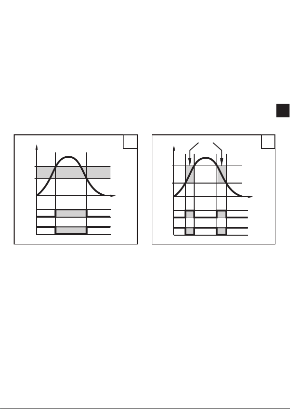
4�2 Pressure monitoring / switching function �������������������������������������������������������5
4�3 Pressure monitoring/ analogue function ��������������������������������������������������������5
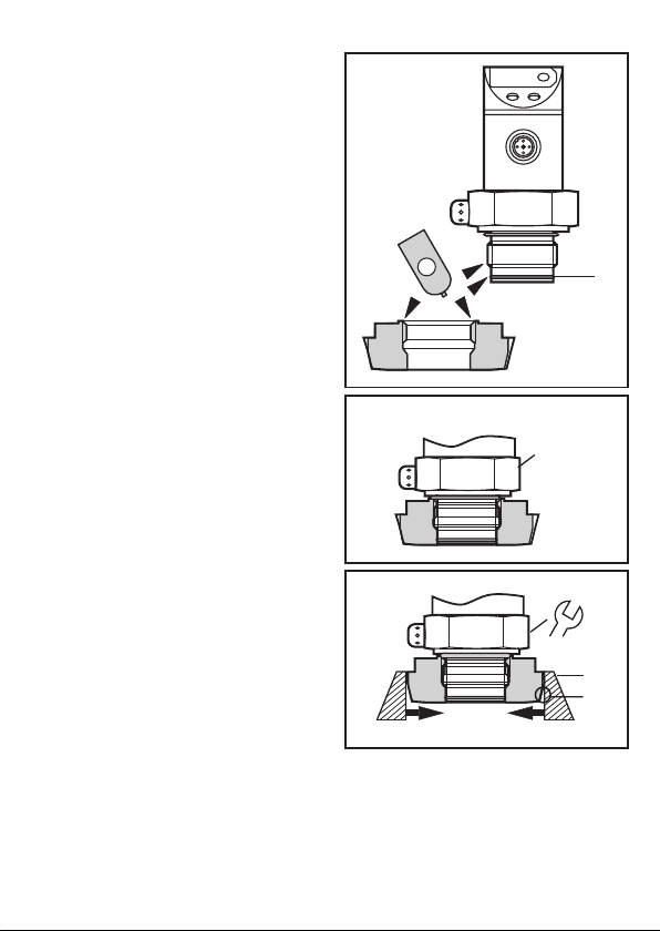
5 Installation������������������������������������������������������������������������������������������������������������7
6 Electrical connection��������������������������������������������������������������������������������������������9
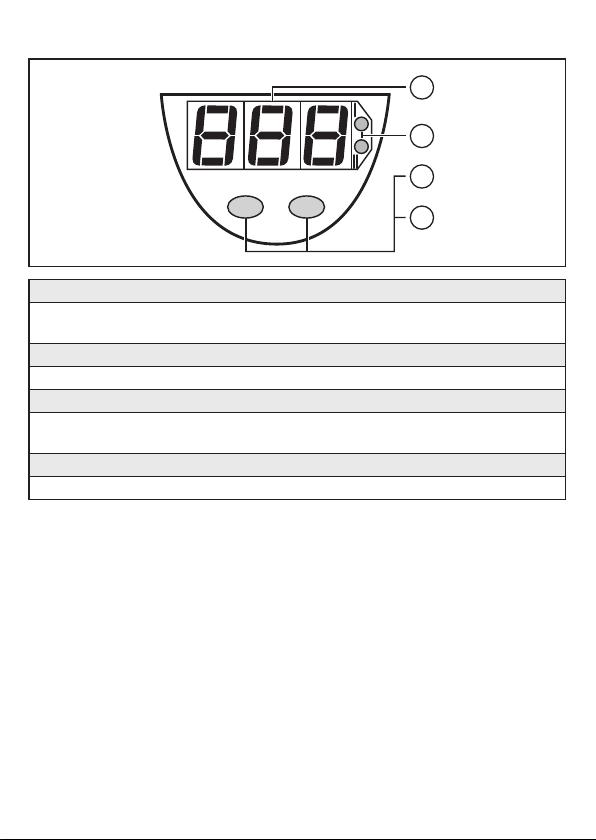
7 Operating and display elements ������������������������������������������������������������������������10
8 Menu������������������������������������������������������������������������������������������������������������������ 11
8�1 Menu structure��������������������������������������������������������������������������������������������� 11
8�2 Menu explanation ����������������������������������������������������������������������������������������12
9 Parameter setting ����������������������������������������������������������������������������������������������13
9�1 Parameter setting general ���������������������������������������������������������������������������13
9�2 Configuring the display (optional) ����������������������������������������������������������������14
9�3 Setting the output signal ������������������������������������������������������������������������������15
9�3�1 Setting the output function������������������������������������������������������������������15
9�3�2 Setting the switching limits �����������������������������������������������������������������15
9�3�3 Scaling the analogue value ����������������������������������������������������������������15
9�4 User settings (optional)��������������������������������������������������������������������������������15
9�4�1 Zero-point calibration��������������������������������������������������������������������������15
9�4�2 Calibration reset ���������������������������������������������������������������������������������15
9�4�3 Setting the delay time for the switching outputs ���������������������������������16
9�4�4 Setting the output polarity�������������������������������������������������������������������16
9�4�5 Setting the damping for the switching signal ��������������������������������������16
9�4�5 Setting the damping for the analogue signal ���������������������������������������16
9�5 Service functions �����������������������������������������������������������������������������������������16
9�5�1 Reading the min�/max� values for the system pressure����������������������16
10 Operation���������������������������������������������������������������������������������������������������������16

3
UK
1 Preliminary note
1.1 Symbols used
►Instruction
> Reaction, result
[…] Designation of buttons, switches or indications
→Cross-reference
Important note
Non-compliance can result in malfunctions or interference�
2 Safety instructions
• The device described is a subcomponent for integration into a system�
- The manufacturer is responsible for the safety of the system�
- The system manufacturer undertakes to perform a risk assessment and to
create a documentation in accordance with legal and normative requirements
to be provided to the operator and user of the system� This documentation
must contain all necessary information and safety instructions for the operator,
the user and, if applicable, for any service personnel authorised by the
manufacturer of the system�
• Read this document before setting up the product and keep it during the entire
service life�
• The product must be suitable for the corresponding applications and
environmental conditions without any restrictions�
• Only use the product for its intended purpose (→ Functions and features).
• Only use the product for permissible media (→ Technical data).
• If the operating instructions or the technical data are not adhered to, personal
injury and/or damage to property may occur�
• The manufacturer assumes no liability or warranty for any consequences
caused by tampering with the product or incorrect use by the operator�
10�1 Read the set parameter values �����������������������������������������������������������������17
10�2 Fault indication ������������������������������������������������������������������������������������������17
10�3 Cleaning of the filter cover�������������������������������������������������������������������������17

4
• Installation, electrical connection, set-up, programming, configuration, operation
and maintenance of the product must be carried out by personnel qualified and
authorised for the respective activity�
• Protect units and cables against damage�
3 Functions and features
The pressure sensor detects the system pressure of machines and installations�
3.1 Applications
Type of pressure: relative pressure
Information on pressure rating and bursting pressure → data sheet.
Static and dynamic overpressures exceeding the indicated overload
pressure are to be avoided by taking appropriate measures�
The indicated bursting pressure must not be exceeded� Even if the
bursting pressure is exceeded only for a short time, the unit can be
destroyed� NOTE: Risk of injury!
4 Function
4.1 Processing of the measured signals
• The unit displays the current system pressure�
• It generates 2 output signals according to the parameter setting�
OUT1 • switching signal for pressure limit values
OUT2
• switching signal for pressure limit values
• analogue signal 4���20 mA
• analogue signal 0���10 V

5
UK
4.2 Pressure monitoring / switching function
OUTx changes its switching state if it is above or below the set switching limits
(SPx, rPx)� The following switching functions can be selected:
• Hysteresis function / normally open: [OUx] = [Hno] (→ fig. 1).
• Hysteresis function / normally closed: [OUx] = [Hnc] (→ fig. 1).
First the set point (SPx) is set, then the reset point (rPx) at the requested
distance�
• Window function / normally open: [OUx] = [Fno] (→ fig. 2).
• Window function / normally closed: [OUx] = [Fnc] (→ fig. 2).
The width of the window can be set by means of the distance between SPx and
rPx� SPx = maximum value, rPx = minimum value�
1 2
P = system pressure; HY = hystereris; FE = window
4.3 Pressure monitoring/ analogue function
The analogue signal can be set�
• [OU2] defines whether the set measuring range is provided as a 4���20 mA
signal ([OU2] = [I]) or a 0���10 V signal ([OU2] = [U])�
• By setting the parameter ASP you define the measured value at which the
output signal is 4 mA / 0 V�
• By setting the parameter AEP you define the measured value at which the
output signal is 20 mA / 10 V�
Minimum distance between [ASP] and [AEP] = 25 % of the final value of the
measuring range (turn down 1:4)�

6
Current output
Factory setting Measuring range scaled
P = system pressure, MEW = final value of the measuring range
The output signal is between 4 and 20 mA� It is also indicated:
• System pressure above the measuring range: output signal > 20 mA �
• System pressure below the measuring range: output signal between 4 and
3�2 mA�
Voltage output
Factory setting Measuring range scaled
P = system pressure, MEW = final value of the measuring range
The output signal is between 0 and 10 V� It is also indicated:
• System pressure above the measuring range: output signal > 10 V�

7
UK
5 Installation
Ensure that no pressure is applied to the installation while mounting or
removing the sensor�
►Screw the sensor into a G¾
process fitting�
►Tighten the sensor with a spanner
until you can feel the end stop�
You can replace the Viton O-ring (B)
by the supplied EPDM O-ring�
36
B
A
A = rotatable housing
Adapters G ¾ ensure that the sensor can be connected to different process
connections� The adapters have to be ordered separately as accessories�
►Mount the adapter (D) to the
sensor�
►Fix sensor + adapter by means
of a coupling nut, a clamp flange
or similar (C) to the process
connection�
If it is not possible to slide the fixing
element (C) down over the top of the
sensor: slide it up over the bottom
of the sensor before the adapter is
mounted�
C
D

8
Mounting the adapter
►Slightly grease the threads and
sealing areas of the sensor and
adapter with lubricating paste (1)�
The paste must be suitable and
approved for the application and
compatible with the elastomers
used�
Recommendation: Klüber paste
UH1 84-201 with USDA-H1
approval for the food industry�
►Make sure that the O-ring (B) is
correctly positioned�
B
1
►Screw the sensor into the adapter
until it is hand-tight� Do not damage
the sealing chamfers�
►Clamp sensor and adapter into a
clamping device (E)� Tighten the
clamping device only slightly so
that the adapter does not warp� The
sealing chamfers (F) must not be
damaged�
►Tighten the sensor using a spanner
until you can feel the end stop�
E
F
36
Welding adapter
First weld the adapter, then mount the sensor� Follow the instructions included
with the adapter�

9
UK
6 Electrical connection
The unit must be connected by a qualified electrician�
The national and international regulations for the installation of electrical
equipment must be adhered to�
Voltage supply to EN50178, SELV, PELV�
►Disconnect power and connect the unit as follows:
2 x p-switching 2 x n-switching
L
L
+
3
4
2
1
BU
BK
WH
BN
2: OUT2
4: OUT1 L
L+
3
4
2
1
BU
BK
WH
BN
2: OUT2
4: OUT1
1 x p-switching / 1 x analogue 1 x n-switching / 1 x analogue
L
L+
3
4
2
1
BU
BK
WH
BN
2: OUT2
4: OUT1 L
L+
3
4
2
1
BU
BK
WH
BN
2: OUT2
4: OUT1
Core colours of ifm sockets:
1 = BN (brown), 2 = WH (white), 3 = BU (blue), 4 = BK (black)

10
7 Operating and display elements
1: 7-segment display
- Display of the system pressure1),
- display of parameters and parameter values�
2: 2 x LED red
- Switching status; lights if output I / II has switched�
3: Set button
- Setting of the parameter values (scrolling by holding pressed; incremental by pressing
briefly)�
4: Mode/Enter button
- Selection of the parameters and acknowledgement of the parameter values�
1) 3-digit display in the minus range: -�XX = - 0,XX

11
UK
8 Menu
8.1 Menu structure
RUN
M
S
M
M
M
S
M
M
S
M
S
M
M
S
M
M
S
M
S
M
M
S
M
S
M
S
M
M
S
M
M
S
M
M
S
M
M
S
M
M
S
M
M
S
M
RUN
M
M
M
M
M
M
M
S
M
M
S
M
M
S
M
M
S
M
S
S
M
OU2 = Hno, Hnc, Fno, Fnc
OU2 = I, U

12
8.2 Menu explanation
SP1/rP1 Maximum / minimum value for system pressure, at which output 1 changes
its switching status�
OU1 Output function for OUT1:
• Switching signal for the limit values: hysteresis function [H ��] or window
function [F ��], normally open [� no] or normally closed [� nc] each�
OU2 Output function for OUT2:
• Switching signal for the limit values: hysteresis function [H ��] or window
function [F ��], normally open [� no] or normally closed [� nc] each��
• Analogue signal for the current system pressure
: 4���20 mA [I], 0���10 V [U]�
SP2/rP2 Maximum / minimum value for system pressure, at which output 2 changes
its switching status�
ASP Analogue start point for the system pressure: measured value at which
4 mA / 0 V are output�
AEP Analogue end point for the system pressure: measured value at which
20 mA / 10 V are output�
EF Extended functions / Opening menu level 2�
HI Maximum value memory for the system pressure�
LO Minimum value memory for the system pressure�
COF Zero point calibration�
CAr Calibration reset�
dS1/dS2 Switch-on delay for OUT1/OUT2�
dr1/dr2 Reset delay for OUT1/OUT2�
P-n Output polarity: pnp / npn
dAP Damping for the switching outputs�
dAA Damping for the analogue signal�
diS Update rate and orientation of the display�
Uni Standard unit of measurement for the system pressure�

13
UK
9 Parameter setting
During the parameter setting process the unit remains in the operating mode�
It continues its monitoring function with the existing parameters until parameter
setting has been terminated�
9.1 Parameter setting general
Each parameter setting requires 3 steps:
1Selecting parameter
►Press [Mode/Enter] until the
requested parameter is displayed�
Mode/Enter Set
2Setting the parameter value
►Press [Set] and keep the buton
pressed�
> Current setting value of the
parameter bit flashes for 5 s�
> After 5 s: Setting value is changed:
incremental by pressing briefly or
scrolling by holding pressed�
Mode/Enter Set
The numerical values are incremented continuously� If the value is to be reduced: Let
the display move to the maximum setting value� Then the cycle starts again at the
minimum setting value�
3Acknowledge parameter value
►Press [Mode/Enter] briefly�
> The parameter is displayed again�
The new setting value is stored�
Mode/Enter Set
Set more parameters
►Start again with step 1�
Finishing parameter setting
►Press [Mode/Enter] several times until the current measured value is displayed or wait
for 15 s�
> The unit returns to the operating mode�

14
• Changing from menu level 1 to menu level 2
►Press [Mode/Enter] until [EF] is displayed.�
►Press [Set] briefly�
> The first parameter of the submenu is displayed (here: [HI])�
• Locking / unlocking
The unit can be locked electronically to prevent unintentional wrong settings�
►Ensure that the unit is in the normal operating mode�
►Press [Mode/Enter] + [Set] for 10 s�
> Indication goes out briefly (acknowledgement of locking / unlocking)�
Units are delivered from the factory in the unlocked state�
With the unit in the locked state [Loc] is indicated briefly when you try
to change parameter values�
• Timeout
If no button is pressed for 15 s while the parameters are being set, the unit returns to
the operating mode with unchanged values�
9.2 Configuring the display (optional)
►Select [Uni] and set the unit of measurement:
- bAr (= bar / mbar),
- PSI,
- PA (= MPa / kPa)�
►Select [diS] and set update rate and orientation of the display
- [d1]: Update of the measured value every 50 ms�
- [d2]: Update of the measured value every 200 ms�
- [d3]: Update of the measured value every 600 ms�
- [Ph] = display of the measured peak value remains for a short time
(peak hold)�
- [rd1], [rd2], [rd3], [rPh]: Display like d1, d2, d3, Ph; rotated by 180°�
- [OFF]: The display is deactivated in the operating mode� If one of the
buttons is pressed, the current measured value is displayed for 15 s�
Another press of the Mode/Enter button opens the Display mode� The
LEDs remain active even if the display is deactivated�

15
UK
9.3 Setting the output signal
9.3.1 Setting the output function
►Select [OU1] and set the switching function:
- [Hno] = hysteresis function / normally open,
- [Hnc] = hysteresis function / normally closed,
- [Fno] = window function / normally open,
- [Fnc] = window function / normally closed�
►Select [OU2] and set the switching function:
- [Hno] = hysteresis function / normally open,
- [Hnc] = hysteresis function / normally closed,
- [Fno] = window function / normally open,
- [Fnc] = window function / normally closed,
- [I] = current signal proportional to the pressure 4…20 mA,
- [U] = voltage signal proportional to the pressure 0���10 V�
9.3.2 Setting the switching limits
►Select [SP1] / [SP2] and set the value at which the output switches�
►Select [rP1] / [rP2] and set the value at which the output switches back�
rPx is always lower than SPx� The unit only accepts values which are lower
than SPx�
9.3.3 Scaling the analogue value
►Select [ASP] and set measured value at which 4 mA / 0 V are output�
►Select [AEP] and set measured value at which 20 mA / 10 V are output�
Minimum distance between ASP and AEP = 25 % of the final value of the
measuring range (scaling factor 1:4)�
9.4 User settings (optional)
9.4.1 Zero-point calibration
►Select [COF] and set a value between -5% and 5% of the final value of
the measuring range� The internal measured value “0” is shifted by this
amount�
9.4.2 Calibration reset
►Select [CAr]�
►Press [SET] until [---] is displayed�
►Press [Mode/Enter] briefly�

16
9.4.3 Setting the delay time for the switching outputs
[dS1] / [dS2] = switch-on delay for OUT1 / OUT2�
[dr1] / [dr2] = switch-off delay for OUT1 / OUT2�
►Select [dS1], [dS2], [dr1] or [dr2], set value between 0�1 und 50 s (at 0�0
the delay time is not active)
9.4.4 Setting the output polarity
►Select [P-n] and set [PnP] or [nPn]�
9.4.5 Setting the damping for the switching signal
►Select [dAP] and set value between 0�01 and 4�00 s (at 0�00 = [dAP] is
not active)�
dAP value = response time between pressure change and change of the
switching status in seconds�
[dAP] influences the switching frequency: fmax = 1 ÷ 2dAP�
[dAP] also affects the display�
9.4.5 Setting the damping for the analogue signal
►Select [dAA] and set a value: 0,0 - 0,1- 0,5 or 2,0 s (at 0�0 = [dAA] is not
active)�
dAA value = response time between pressure change and change of the
analogue signal in seconds�
9.5 Service functions
9.5.1 Reading the min./max. values for the system pressure
►[Select [HI] or [LO], press [Set] briefly�
[HI] = maximum value, [LO] = minimum value�
Delete memory:
►Select [HI] or [LO]�
►Press [SET] until [---] is displayed�
►Press [Mode/Enter] briefly�
10 Operation
After power on of the supply voltage the unit is in the Run mode (= normal
operation)� It carries out its measurement and evaluation functions and generates
output signals according to the set parameters�
Operating indicators → 7 Operating and display elements�

17
UK
10.1 Read the set parameter values
►Press [Mode/Enter] until the requested parameter is displayed�
►Press [Set] briefly�
> The unit displays the corresponding parameter value for about 15 s� After
another 15 s the unit returns to the Run mode�
10.2 Fault indication
[OL] Overload (presure above measuring range of the sensor)�
[UL] Underload (pressure below measuring range of the sensor)�
[SC1] Flashing: short circuit in the switching output 1*�
[SC2] Flashing: short circuit in the switching output 2*�
[SC] Flashing: short circuit in both switching outputs*�
*The output concerned is switched off as long as the short circuit exists�
10.3 Cleaning of the filter cover
If viscous and residues producing
media clog the filter cover of
the sensor (and thus reduce the
measuring accuracy slightly), you can
clean it�
►Unscrew the filter cover (B) (use a
pair of pliers with plastic-covered
jaws for this)�
►Clean the cover thoroughly�
AB
The vent (A) should only be cleaned by skilled personnel and with utmost care�
Possible medium residues must not be compressed and pressed into the vent�
This could clog the filter system and reduce the measuring accuracy of the
sensor�
►Screw the filter cover again tightly�
More information at www�ifm�com
Table of contents
Other IFM Accessories manuals

IFM
IFM OID20 Series User manual

IFM
IFM PI109 Series User manual

IFM
IFM Efector 160 LK8 User manual

IFM
IFM O1D120 User manual

IFM
IFM JD Application guide

IFM
IFM SBY2 Series User manual

IFM
IFM UGR500 User manual

IFM
IFM OY90 S Series User manual

IFM
IFM Efector 500 PI30 User manual

IFM
IFM Efector 500 PI2652 User manual

IFM
IFM OY Series User manual

IFM
IFM SB4 Series User manual

IFM
IFM Efector 200 OJ User manual

IFM
IFM Efector 410 Application guide

IFM
IFM JD Series Application guide

IFM
IFM O5D15 Series User manual

IFM
IFM Efector 500 PY2068 User manual

IFM
IFM SBU3 Series User manual

IFM
IFM SDP110 User manual

IFM
IFM O1D111 User manual