IFM PI22 Series User manual

Operating instructions
Electronic pressure sensor
PI22xx
PI23xx
80009157 / 01 07 / 2018
UK

2
Contents
1 Preliminary note���������������������������������������������������������������������������������������������������4
1�1 Symbols used ������������������������������������������������������������������������������������������������4
2 Safety instructions �����������������������������������������������������������������������������������������������4
3 Functions and features ����������������������������������������������������������������������������������������5
3�1 Applications ���������������������������������������������������������������������������������������������������5
4 Function���������������������������������������������������������������������������������������������������������������5
4�1 Operating modes �������������������������������������������������������������������������������������������6
4�1�1 2-wire operation������������������������������������������������������������������������������������6
4�1�2 3-wire operation������������������������������������������������������������������������������������6
4�2 Switching function (only for 3-wire operation)������������������������������������������������6
4�3 Analogue function ������������������������������������������������������������������������������������������7
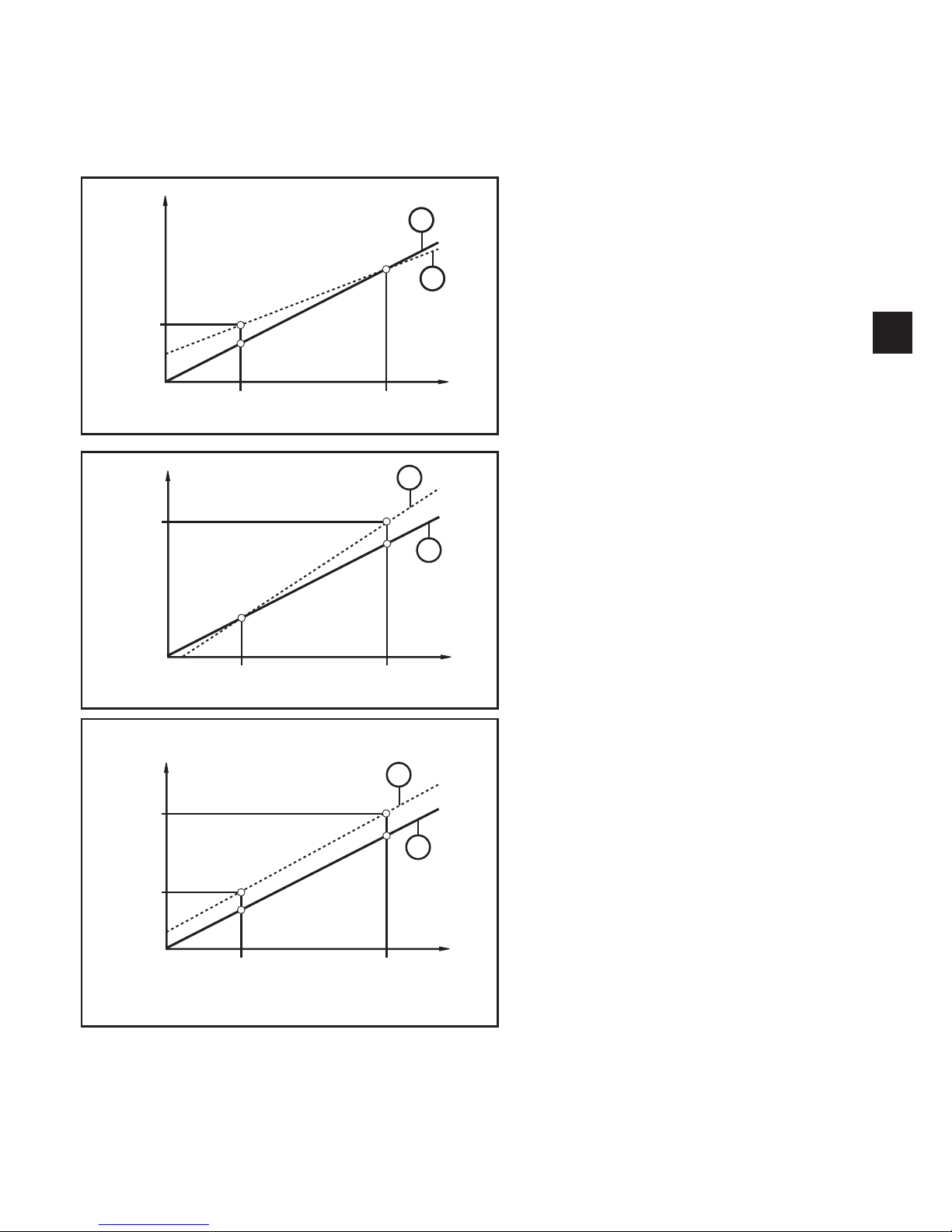
4�4 Customer-specific calibration ������������������������������������������������������������������������8
4�5 IO-Link ���������������������������������������������������������������������������������������������������������10
4�5�1 General information ����������������������������������������������������������������������������10
4�5�2 Device-specific information�����������������������������������������������������������������10
4�5�3 Parameter setting tools�����������������������������������������������������������������������10
5 Installation����������������������������������������������������������������������������������������������������������10
5�1 Connection versions clamp seals ���������������������������������������������������������������10
6 Electrical connection������������������������������������������������������������������������������������������12
6�1 Connection for 2-wire operation ������������������������������������������������������������������12
6�2 Connection for IO-Link parameter setting����������������������������������������������������12
6�3 Connection for 3-wire operation ������������������������������������������������������������������13
7 Operating and display elements ������������������������������������������������������������������������14
8 Menu������������������������������������������������������������������������������������������������������������������15
8�1 Menu structure: main menu�������������������������������������������������������������������������15
8�2 Explanation of the main menu ���������������������������������������������������������������������16
8�3 Menu structure: level 2 (extended functions)�����������������������������������������������17
8�4 Explanation of menu level 2 ������������������������������������������������������������������������18
8�5 Menu structure: level 3 (simulation)�������������������������������������������������������������19
8�6 Explanation of menu level 3 ������������������������������������������������������������������������20
9 Parameter setting ����������������������������������������������������������������������������������������������21
9�1 Parameter setting in general �����������������������������������������������������������������������21

3
UK
9�2 Configure display (optional)�������������������������������������������������������������������������23
9�3 Set output signals ����������������������������������������������������������������������������������������24
9�3�1 Set output functions����������������������������������������������������������������������������24
9�3�2 Set switching limits �����������������������������������������������������������������������������24
9�3�3 Scale analogue value for OUT2 ���������������������������������������������������������25
9�4 User settings (optional)��������������������������������������������������������������������������������26
9�4�1 Carry out zero point calibration ����������������������������������������������������������26
9�4�2 Set output status in fault condition������������������������������������������������������26
9�4�3 Set delay time for the switching outputs ���������������������������������������������26
9�4�4 Set output logic for the switching outputs �������������������������������������������26
9�4�5 Set damping for the switching signal ��������������������������������������������������27
9�4�6 Set damping for the analogue signal ��������������������������������������������������27
9�4�7 Calibrate curve of measured values ���������������������������������������������������27
9�5 Service functions �����������������������������������������������������������������������������������������28
9�5�1 Read min/max values for the system pressure ����������������������������������28
9�5�2 Reset all parameters to factory setting �����������������������������������������������28
9�6 Simulation function ��������������������������������������������������������������������������������������28
9�6�1 Open menu level 3 (simulation)����������������������������������������������������������28
9�6�2 Set simulation value ���������������������������������������������������������������������������29
9�6�3 Set time for simulation ������������������������������������������������������������������������29
9�6�4 Start simulation�����������������������������������������������������������������������������������29
10 Operation���������������������������������������������������������������������������������������������������������30
10�1 Read the set parameters ���������������������������������������������������������������������������30
10�2 Change the display in the Run mode �������������������������������������������������������30
10�3 Self-diagnostics / fault indications �������������������������������������������������������������30
11 Technical data ��������������������������������������������������������������������������������������������������33
11�1 Setting ranges��������������������������������������������������������������������������������������������33
11�2 Technical data ��������������������������������������������������������������������������������������������33
12 Factory setting �������������������������������������������������������������������������������������������������34

4
1 Preliminary note
1.1 Symbols used
►Instructions
> Reaction, result
[…] Designation of keys, buttons or indications
→Cross-reference
Important note
Non-compliance may result in malfunction or interference�
Information
Supplementary note�
2 Safety instructions
• Read this document before setting up the product and keep it during the entire
service life�
• The product must be suitable for the corresponding applications and
environmental conditions without any restrictions�
• Only use the product for its intended purpose
(→ Functions and features).
• Only use the product for permissible media (→ Technical data).
• If the operating instructions or the technical data are not adhered to, personal
injury and/or damage to property may occur�
• The manufacturer assumes no liability or warranty for any consequences
caused by tampering with the product or incorrect use by the operator�
• Installation, electrical connection, set-up, operation and maintenance of the
product must be carried out by qualified personnel authorised by the machine
operator�
• Protect units and cables against damage�

5
UK
3 Functions and features
The unit measures and monitors the system pressure in a plant�
3.1 Applications
Type of pressure: relative pressure
Order no. Measuring range
Permissible
overload
pressure
Bursting
pressure
bar PSI bar PSI bar PSI
PI2xx9 -1���1 -14�5���14�5 10 145 30 435
PI2xx7 -0�05���1 -0�73���14�5 10 145 30 435
PI2xx6 -0�124���2�5 -1�8���36�27 20 290 50 725
PI2xx5 -1���4 -14�5���58 30 435 50 725
PI2xx4 -1���10 -14�5���145 50 725 100 1450
PI2xx3 -1���25 -14�4���362�7 80 1160 150 2175
Avoid static and dynamic overpressure exceeding the specified overload
pressure by taking appropriate measures�
The indicated bursting pressure must not be exceeded�
Even if the bursting pressure is exceeded only for a short time, the unit
may be destroyed� ATTENTION: risk of injury!
Not suitable for use where the criteria for paragraph D10�2/63-03 of the 3-A
standard 63-03 have to be met�
4 Function
• The unit displays the current system pressure�
• It generates output signals according to the operating mode and the parameter
setting�
• Moreover, it provides the process data via IO-Link�
• The unit is designed for fully bidirectional communication�
So the following options are possible:
- Remote display: reading and display of the current system pressure�
- Remote parameter setting: reading and changing the current parameter
setting�
- IO-Link parameter setting (→ 4.5)

6
4.1 Operating modes
The operating mode is defined by the wiring (→ 6 Electrical connection) and
automatically recognised by the unit�
4.1.1 2-wire operation
OUT2 (pin 2) Analogue signal proportional to pressure 4…20 mA or 20���4 mA
4.1.2 3-wire operation
OUT1 (pin 4) • Switching signal for system pressure limit
• Communication via IO-Link
OUT2 (pin 2)
3 options:
• Switching signal for system pressure limit
• Analogue signal proportional to pressure 4���20 mA
• Analogue signal proportional to pressure 20���4 mA
4.2 Switching function (only for 3-wire operation)
OUTx changes its switching status if it is above or below the set switching limits
(SPx, rPx)� The following switching functions can be selected:
• Hysteresis function / normally open: [OUx] = [Hno] (→ fig. 1).
• Hysteresis function / normally closed: [OUx] = [Hnc] (→ fig. 1).
First the set point (SPx) is set, then the reset point (rPx) with the requested
difference�
• Window function / normally open: [OUx] = [Fno] (→ fig. 2).
• Window function / normally closed: [OUx] = [Fnc] (→ fig. 2).
The width of the window can be set by means of the difference between SPx
and rPx� SPx = upper value, rPx = lower value�

7
UK
1 2
P = system pressure; HY = hysteresis; FE = window
4.3 Analogue function
The analogue output can be configured�
• [OU2] defines whether the set measuring range is provided as 4���20 mA
([OU2] = [I]) or as 20���4 mA ([OU2] = [InEG])�
Scaling can be set by means of the teach process or by entering a value for the
parameters ASP and AEP�
• Teaching the analogue start point [tASP] or setting the parameter [ASP] defines
at which measured value the output signal is 4 mA (20 mA with [InEG])�
• Teaching the analogue end point [tAEP] or setting the parameter [AEP] defines
at which measured value the output signal is 20 mA (4 mA with [InEG])�

8
Minimum distance between [ASP] and [AEP] = 25 % of the final value of the
measuring range (turn-down 1:4); for PI2x09: 25 % of the measuring span�
Factory setting Measuring range scaled
P = system pressure , MAW = initial value of the measuring range, MEW = final value of
the measuring range
1
: [OU2] = [I]
2
: [OU2] = [InEG]
In the set measuring range the output signal is between 4 and 20 mA ([OU2] = [I])
or between 20 and 4 mA ([OU2] = [InEG])�
It is also indicated:
• System pressure above the measuring range:
- Output signal > 20 mA if [OU2] = [I]�
- Output signal 4 to 3�8 mA if [OU2] = [InEG]�
• System pressure below the measuring range:
- Output signal 4 to 3�8 mA if [OU2] = [I]�
- Output signal > 20 mA if [OU2] = [InEG]�
4.4 Customer-specific calibration
The customer-specific calibration changes the curve of measured values
compared to the real measured values (shifting / change of the gradient → 9.4.6
[CAL])�
• Two calibration points can be defined (CP1, CP2)� The two points are
independent of each other�
• The two calibration points must be within the scaled measuring range (→ 4.3
Pressure monitoring / analogue function)�

9
UK
• The zero point calibration [COF] influences the calibration of the curve of
measured values. Recommendation: set [COF] to 0 (→ 9.4.1 [COF]), then
calibrate the curve of measured values�
After a change the calibration can be reset to factory setting (→ 9.5.2 [rES]).
• P = measured pressure
P‘ = modified measured value
• CP1 = calibration point 1
CP1‘ = modified measured value for
CP1
• CP2 = calibration point 2
• 1 = curve of measured values with
factory setting
• 2 = curve of measured values after
calibration
• P = measured pressure
P‘ = modified measured value
• CP1 = calibration point 1
CP2 = calibration point 2
CP2‘ = modified measured value for
CP2
• 1 = curve of measured values with
factory setting
• 2 = curve of measured values after
calibration
• P = measured pressure
P‘ = modified measured value
• CP1 = calibration point 1
CP1‘ = modified measured value for
CP1
• CP2 = calibration point 2
CP2‘ = modified measured value for
CP2
• 1 = curve of measured values with
factory setting
• 2 = curve of measured values after
calibration

10
4.5 IO-Link
4.5.1 General information
This unit has an IO-Link communication interface which requires an IO-Link-
capable module (IO-Link master) for operation�
The IO-Link interface enables direct access to the process and diagnostic data
and provides the possibility to set the parameters of the unit during operation�
In addition, communication is possible via a point-to-point connection with a USB
adapter cable�
More information about IO-Link → www�ifm�com�
4.5.2 Device-specific information
IODDs necessary for the configuration of the IO-Link unit and detailed information
about process data structure, diagnostic information and parameter addresses →
www�ifm�com�
4.5.3 Parameter setting tools
All necessary information about the required IO-Link hardware and software →
www�ifm�com�
5 Installation
5.1 Connection versions clamp seals
Clamp
connection to
pipe to DIN
11866
Effective diameter
PI22xx:
Deff = 34 mm
Effective diameter
PI23xx:
Deff = 47�5 mm
d1
d2
Series A - metric nominal width
DN 40
Di = 38 mm
nominal width
DN 50
Di = 50 mm
Series B - ISO nominal width
DN / OD 42�4
Di = 38�4 mm
--------------------
Series C -
ASME
nominal width
DN / OD 1 ½“
Di = 34�8 mm
nominal width
DN / OD 2“
Di = 47�5 mm
Internal pipe diameter Di (d2) > diameter of the
effective area of the diaphragm Deff (d1)�

11
UK
►Before installing and removing the unit: Make sure that no pressure
is applied to the system� Please note when the system pressure is
displayed in % of the span: "0" does not mean that no pressure is
applied to the system!
►The diaphragm must not be dented or cleaned with pointed or hard
objects!
►The system seal must not be in contact with the diaphragm�
The installation position of the sensor influences the hydrostatic pressure
of the fill fluid in the capillary tube of the diaphragm seal unit� A zero shift
(i�e� when no pressure is applied to the system, "zero" is not displayed
as a measured value) as a consequence of the installation position of the
sensor can be corrected via the menu (→ 9.4.1)�
Use in hygienic areas to 3-A: orientation of the unit in pipes and tanks
Please note for optimised cleaning of
the measuring element according to
the 3-A criteria for hygienic areas:
To ensure that the medium can
completely flow off the area of the
diaphragm seal when the pipes or
tanks are empty, choose positions 1 - 3
of the generally possible installation
positions 1 - 5 (see figure on the right)�
Use in hygienic areas to EHEDG:
►Make sure that the sensor is integrated into the system according to EHEDG�
►Use seals with defined seal compression!

12
6 Electrical connection
The unit must be connected by a qualified electrician�
The national and international regulations for the installation of electrical
equipment must be adhered to�
Voltage supply according to EN 50178, SELV, PELV�
►Disconnect power�
►Connect the unit as follows:
6.1 Connection for 2-wire operation
BN
WH
1
2
Colours to DIN EN 60947-5-2
6.2 Connection for IO-Link parameter setting
BN
WH
BK
BU
1
2
3
4
L+
L
P
Colours to DIN EN 60947-5-2
Pin 1 L+
Pin 2 Output function according to the OU2 setting
Pin 3 L- for programming mode
Pin 4 (P) Communication via IO-Link

13
UK
6.3 Connection for 3-wire operation
2 x pnp 2 x npn
L
L+
Out 1
Out 2
4:
2:
L
L+
Out 1
Out 2
4:
2:
BN
WH
BK
BU
1
2
3
4
L
L+
Out 1
Out 2
4:
2:
BN
WH
BK
BU
1
2
3
4
1 x pnp / 1 x analogue 1 x npn / 1 x analogue
L+
L
Out 1
Out 2
4:
2:
BN
WH
BK
BU
1
2
3
4
L+
L
Out 1
Out 2
4:
2:
BN
WH
BK
BU
1
2
3
4
Colours to DIN EN 60947-5-2
Pin 1 L+
Pin 3 L-
Pin 4 (OUT1) • Binary switching output pressure monitoring
• Communication via IO-Link
Pin 2 (OUT2) Binary switching output pressure monitoring or analogue output for
system pressure

14
7 Operating and display elements
10
9
11
Mode/Enter Set
1 2 3 4 5 6 78
1 to 8: Indicator LEDs
- LED 1 to LED 5 = system pressure in the specified unit of measurement�
- LED 6 = system pressure in % of the set scaling of the analogue output (range ASP to
AEP) if [OU2] is configured as analogue output�
System pressure in % of the final value of the measuring range if [OU2] is configured as
switching output�
- LED 7 = switching status OUT2 (on if output 2 is switched)�
- LED 8 = switching status OUT1 (on if output 1 is switched)�
9: Alphanumeric display, 4 digits
- Display of the current system pressure�
- Display of the parameters and parameter values�
10: Set button
- Setting of the parameter values (scrolling by holding pressed, incrementally by pressing
once)�
11: Mode/Enter button
- Selection of the parameters and acknowledgement of the parameter values�

15
UK
8 Menu
8.1 Menu structure: main menu
RUN
S
M
M
S
M
M
S
M
M
S
M
S
M
S
M
M
1
M
M
S
M
M
S
M
M
M
S
M
M
S
M
M
S
M
1: Change to menu level 2 (extended functions)
Menu items highlighted in grey ( SP1 ) are not active in 2-wire operation�

16
8.2 Explanation of the main menu
SP1/rP1* Upper / lower limit for system pressure at which OUT1 switches�
OU1* Output function for OUT1:
• Switching signal for the pressure limits: hysteresis function [H ��] or window
function [F ��], either normally open [� no] or normally closed [� nc]�
OU2 Output function for OUT2:
• Switching signal for the pressure limits: hysteresis function [H ��] or window
function [F ��], either normally open [� no] or normally closed [� nc]
(only available for 3-wire operation)�
• Analogue signal for the current system pressure: 4���20 mA [I],
20���4 mA [InEG]�
tCOF Teach zero-point calibration�
tASP Teach analogue start point for system pressure: set measured value at which
4 mA is provided (20 mA if [OU2] = [InEG])�
tAEP Teach analogue end point for system pressure: set measured value at which
20 mA is provided (4 mA if [OU2] = [InEG])�
SP2/rP2* Upper / lower limit for system pressure at which OUT2 switches�
EF Extended functions / opening of menu level 2�
* menu items not active in 2-wire operation

17
UK
8.3 Menu structure: level 2 (extended functions)
M
M
S
M
M
S
M
M
S
M
M
S
M
M
S
M
S
M
M
S
M
M
S
M
M
S
1
1
M
M
M
S
M
M
S
M
S
M
S
M
S
M
S
M
M
M
M
M
M
S
M
M
S
M
M
S
M
M
M
S
M
S
M
S
2
S
M
1: Change to the main menu, 2: Change to menu level 3 (simulation)�
Menu items highlighted in grey ( ASP ) are not active in 2-wire operation�

18
8.4 Explanation of menu level 2
Uni Standard unit of measurement for system pressure�
SELd
Display mode:
• Pressure in the unit set in [Uni]�
• Pressure in % of the set scaling of the analogue output�
ASP Analogue start point for system pressure: measured value at which 4 mA is
provided (20 mA if [OU2] = [InEG])�
AEP Analogue end point for system pressure: measured value at which 20 mA is
provided (4 mA if [OU2] = [InEG])�
HI Maximum value memory for system pressure�
LO Minimum value memory for system pressure�
COF Zero-point calibration�
dS1* Switch-on delay for OUT1�
dr1* Switch-off delay for OUT1�
dS2* Switch-on delay for OUT2, only active if [OU2] = [Hnc], [Hno], [Fnc] or [Fno]�
dr2* Switch-off delay for OUT2, only active if [OU2] = [Hnc], [Hno], [Fnc] or [Fno]�
FOU1* Status of output 1 in case of an internal fault�
FOU2 Status of output 2 in case of an internal fault�
P-n* Switching logic for the outputs: pnp or npn�
dAP Damping for switching outputs and display�
dAA Damping for analogue output (OUT2), also has an effect on the IO-Link
process value�
diS Update rate and orientation of the display�
CAL Calibration function (setting the curve of measured values)�
CP1 Calibration point 1�
CP2 Calibration point 2�
SIM Change to menu level 3 (simulation)�
rES Restore factory setting�
* menu items not active in 2-wire operation

19
UK
8.5 Menu structure: level 3 (simulation)
With setting SEL = OU
2
2
M
S
M
M
S
M
M
S
M
M
S
M
S
M
2 s
1...60 min
M
With setting SEL = Proc
2
2
M
S
M
M
S
M
M
S
M
S
M
2 s
1...60 min
M
2: Change to menu level 2 (extended functions)
Menu items highlighted in grey ( S�OU1 ) are not active in 2-wire operation�

20
8.6 Explanation of menu level 3
With setting SEL = OU
SEL Status to be simulated:
• Output functions [OU]�
S�OU1* Simulation values for OUT1, only active for 3-wire operation and if
[SEL] = [OU]�
• Output inactive [OPEN] or output active [CLOS]�
S�OU2 Simulation values for OUT2, only active if [SEL] = [OU]�
• For 3-wire operation and if OUT2 has been configured as switching output:
output inactive [OPEN] or active [CLOS]�
• If OUT2 is set as analogue output: analogue signal between 3�6 and
21.1 mA (depending on the set value → 9.6.2).
S�TIM Time for the simulation process in minutes�
S�ON
Start of the simulation process�
During the simulation process the display alternately shows [SIM] and the
current operation indication (→ 9.6.4).
If the simulation process is aborted (briefly press [Mode/Enter] or [Set])
[S�OFF] is indicated for 2 s, then [SEL] is active again�
* menu item not active in 2-wire operation
With setting SEL = Proc
SEL Status to be simulated:
• Process value [Proc]�
S�Pr Simulation of a process value, only active if [SEL] = [Proc]�
• Any value between initial value of the measuring range and final value of
the measuring range�
S�TIM Time for the simulation process in minutes�
S�ON
Start of the simulation process�
During the simulation process the display alternately shows [SIM] and the
current operation indication (→ 9.6.4).
If the simulation process is aborted (briefly press [Mode/Enter] or [Set])
[S�OFF] is indicated for 2 s, then [SEL] is active again�
This manual suits for next models
1
Table of contents
Other IFM Accessories manuals

IFM
IFM O2D50 Series User manual

IFM
IFM Efector 200 O4P5 Series User manual

IFM
IFM OJ51 Series User manual

IFM
IFM PM16 Series User manual

IFM
IFM UIT501 User manual

IFM
IFM OG User manual

IFM
IFM Efector 200 OGE08 Series User manual

IFM
IFM 402946 User manual

IFM
IFM O4E5 Series User manual

IFM
IFM Efector 500 PI30 User manual
Popular Accessories manuals by other brands

Jumpking
Jumpking JumpPOD Classic Premium user guide

Sygonix
Sygonix 2377683 operating instructions

PCB Piezotronics
PCB Piezotronics 350C04 Installation and operating manual

Leviton
Leviton 9864-LED installation instructions

Perenio
Perenio Power Link Device PEHPL01 quick start guide

Mixx
Mixx C10 How-to guide