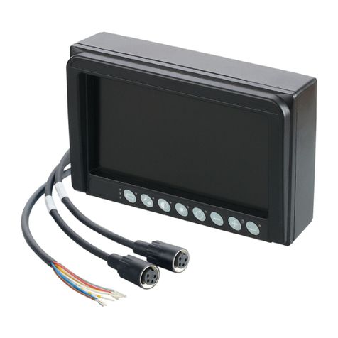
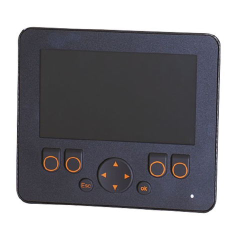
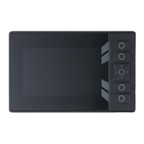
IFM ecomatDisplay CR1058 User manual

Installation instructions
Process and dialogue module
ecomatDisplay
CR1058
CR1059
80289590 / 00 09 / 2020
UK

Process and dialogue module ecomatDisplay CR1058, CR1059
2
Contents
1 Preliminary note � � � � � � � � � � � � � � � � � � � � � � � � � � � � � � � � � � � � � � � � � � � � � � � � � 4
1�1 Key to the symbols � � � � � � � � � � � � � � � � � � � � � � � � � � � � � � � � � � � � � � � � � � � 4
2 Safety instructions � � � � � � � � � � � � � � � � � � � � � � � � � � � � � � � � � � � � � � � � � � � � � � � 5
2�1 Electromagnetic compatibility� � � � � � � � � � � � � � � � � � � � � � � � � � � � � � � � � � � 5
3 Functions and features � � � � � � � � � � � � � � � � � � � � � � � � � � � � � � � � � � � � � � � � � � � � 6
3�1 Application example � � � � � � � � � � � � � � � � � � � � � � � � � � � � � � � � � � � � � � � � � � 6
3�2 Overview of the common characteristics � � � � � � � � � � � � � � � � � � � � � � � � � � 7
3�3 Distinctive features � � � � � � � � � � � � � � � � � � � � � � � � � � � � � � � � � � � � � � � � � � � 7
4 Installation � � � � � � � � � � � � � � � � � � � � � � � � � � � � � � � � � � � � � � � � � � � � � � � � � � � � � 8
4�1 Mounting accessories� � � � � � � � � � � � � � � � � � � � � � � � � � � � � � � � � � � � � � � � � 8
4�2 General installation instructions � � � � � � � � � � � � � � � � � � � � � � � � � � � � � � � � � 8
4�2�1 Locator for mounting accessories � � � � � � � � � � � � � � � � � � � � � � � � � � � 9
4�2�2 Light sensor and status LED � � � � � � � � � � � � � � � � � � � � � � � � � � � � � � 10
4�3 Panel mounting / control cabinet installation � � � � � � � � � � � � � � � � � � � � � � 10
4�3�1 Safety instructions for panel mounting / control cabinet installation 10
4�3�2 Integration with installation kit � � � � � � � � � � � � � � � � � � � � � � � � � � � � � 12
4�3�3 Panel cut-out � � � � � � � � � � � � � � � � � � � � � � � � � � � � � � � � � � � � � � � � � � 12
4�3�4 Mounting steps� � � � � � � � � � � � � � � � � � � � � � � � � � � � � � � � � � � � � � � � � 13
4�4 Surface mounting with RAM®Mount system � � � � � � � � � � � � � � � � � � � � � � 14
4�4�1 Mounting steps� � � � � � � � � � � � � � � � � � � � � � � � � � � � � � � � � � � � � � � � � 15
4�5 Other installation types� � � � � � � � � � � � � � � � � � � � � � � � � � � � � � � � � � � � � � � 15
5 Electrical connection� � � � � � � � � � � � � � � � � � � � � � � � � � � � � � � � � � � � � � � � � � � � � 16
5�1 Wiring � � � � � � � � � � � � � � � � � � � � � � � � � � � � � � � � � � � � � � � � � � � � � � � � � � � � 16
5�2 Connection accessories � � � � � � � � � � � � � � � � � � � � � � � � � � � � � � � � � � � � � � 17
5�3 Connection technology� � � � � � � � � � � � � � � � � � � � � � � � � � � � � � � � � � � � � � � 17
5�4 General wiring information � � � � � � � � � � � � � � � � � � � � � � � � � � � � � � � � � � � � 18
5�5 Operating voltage and fuses � � � � � � � � � � � � � � � � � � � � � � � � � � � � � � � � � � 19
5�6 Shield connection � � � � � � � � � � � � � � � � � � � � � � � � � � � � � � � � � � � � � � � � � � � 19
5�7 Ethernet interface � � � � � � � � � � � � � � � � � � � � � � � � � � � � � � � � � � � � � � � � � � � 20
5�8 Analogue video inputs � � � � � � � � � � � � � � � � � � � � � � � � � � � � � � � � � � � � � � � 20
5�9 USB interfaces � � � � � � � � � � � � � � � � � � � � � � � � � � � � � � � � � � � � � � � � � � � � � 21
5�9�1 Short-circuit protection � � � � � � � � � � � � � � � � � � � � � � � � � � � � � � � � � � � 22
5�10 Selection of loudspeakers � � � � � � � � � � � � � � � � � � � � � � � � � � � � � � � � � � � 22
6 Set-up � � � � � � � � � � � � � � � � � � � � � � � � � � � � � � � � � � � � � � � � � � � � � � � � � � � � � � � � 22
6�1 General� � � � � � � � � � � � � � � � � � � � � � � � � � � � � � � � � � � � � � � � � � � � � � � � � � � 22
6�2 Getting started � � � � � � � � � � � � � � � � � � � � � � � � � � � � � � � � � � � � � � � � � � � � � 23
6�3 Set-up� � � � � � � � � � � � � � � � � � � � � � � � � � � � � � � � � � � � � � � � � � � � � � � � � � � � 23
6�4 Required documentation � � � � � � � � � � � � � � � � � � � � � � � � � � � � � � � � � � � � � 23
6�5 Use of the internal temperature sensor � � � � � � � � � � � � � � � � � � � � � � � � � � 24
7 Technical data� � � � � � � � � � � � � � � � � � � � � � � � � � � � � � � � � � � � � � � � � � � � � � � � � � 25
7�1 CR1058 � � � � � � � � � � � � � � � � � � � � � � � � � � � � � � � � � � � � � � � � � � � � � � � � � � 25

UK
Process and dialogue module ecomatDisplay CR1058, CR1059
3
7�2 CR1059 � � � � � � � � � � � � � � � � � � � � � � � � � � � � � � � � � � � � � � � � � � � � � � � � � � 31
8 Maintenance, repair and disposal� � � � � � � � � � � � � � � � � � � � � � � � � � � � � � � � � � � 37
8�1 Battery change � � � � � � � � � � � � � � � � � � � � � � � � � � � � � � � � � � � � � � � � � � � � � 37
8�2 Cleaning the display surface � � � � � � � � � � � � � � � � � � � � � � � � � � � � � � � � � � 38
8�3 Cleaning the housing surface� � � � � � � � � � � � � � � � � � � � � � � � � � � � � � � � � � 39
8�4 Repair� � � � � � � � � � � � � � � � � � � � � � � � � � � � � � � � � � � � � � � � � � � � � � � � � � � � 39
8�5 Disposal � � � � � � � � � � � � � � � � � � � � � � � � � � � � � � � � � � � � � � � � � � � � � � � � � � 39
9 Approvals/standards � � � � � � � � � � � � � � � � � � � � � � � � � � � � � � � � � � � � � � � � � � � � � 39
This document is the original instructions�
Licences and trademarks
All trademarks and company names used are subject to the copyright of the respective companies�

Process and dialogue module ecomatDisplay CR1058, CR1059
4
1 Preliminary note
Technical data, approvals, accessories and further information at
www�ifm�com�
1.1 Key to the symbols
►Instruction
> Reaction, result
[…] Designation of keys, buttons or indications
→Cross-reference
Important note
Non-compliance may result in malfunction or interference�
Information
Supplementary note
WARNING!
Warning of serious personal injury�
Death or serious irreversible injuries may result�
CAUTION!
Warning of personal injury�
Slight reversible injuries may result�
NOTE!
Warning of damage to property�

UK
Process and dialogue module ecomatDisplay CR1058, CR1059
5
2 Safety instructions
●The device described is a subcomponent for integration into a system� The
manufacturer is responsible for the safety of the system� The system creator
undertakes to perform a risk assessment and to create documentation
in accordance with legal and normative requirements to be provided to
the operator and user of the system� This documentation must contain all
necessary information and safety instructions for the operator, the user and, if
applicable, for any service personnel authorised by the system creator�
●Read this document before setting up the product and keep it during the entire
service life�
●The product must be suitable for the corresponding applications and
environmental conditions without any restrictions�
●Only use the product for its intended purpose (→ 3 Functions and features)�
●If the operating instructions or the technical data are not adhered to, personal
injury and/or damage to property may occur�
●In case of malfunctions, please contact the manufacturer� Tampering with the
unit is not allowed�
●Installation, electrical connection, set-up, programming, configuration,
operation and maintenance of the product must be carried out by personnel
qualified and authorised for the respective activity�
●Protect units, connectors and cables against damage�
●Replace damaged units, since otherwise the technical data and safety will be
impaired�
2.1 Electromagnetic compatibility
This is a class A product� It can cause radio interference in domestic areas� In this
case the operator is requested to take appropriate measures�

Process and dialogue module ecomatDisplay CR1058, CR1059
6
3 Functions and features
The process and dialogue module ecomatDisplay is a programmable graphic
display for controlling, parameter-setting and operation of mobile machines and
plants� It is designed for use up to a height of 3,000 m above mean sea level even
in difficult conditions such as increased temperature range and mechanical load,
see (→ 7 Technical data) and specified standards�
Permissible use:
● in mobile machinery with supply from on-board systems (with battery) of 12 V
DC or 24 V DC nominal voltage
● in industrial environments as fixed device with supply from SELV/PELV in
accordance with the technical data
●also in wet environments
● also outdoors, if necessary with additional UV protection
Communication with other system components, e�g� decentralised I/O modules, is
handled via CAN, Ethernet and USB interfaces� Together with the Linux operating
system they form a universal platform for networking and communication with
other CAN devices, networks or PCs�
The device is not approved for safety-related tasks in the field of operator
protection�
Direct connection to IT structures is not planned for this device� If this
application is required, the users have to implement it (e�g� by using their
own additional components).
3.1 Application example
Networking of 2 analogue cameras with an ecomatDisplay
1� ecomatDisplay (e.g. CR1059)
2� analogue cameras (e.g. 2 x O2M200)

UK
Process and dialogue module ecomatDisplay CR1058, CR1059
7
3.2 Overview of the common characteristics
●5" colour display
●Closed metal housing suitable for panel mounting and surface mounting
outside or in the cabin
●Freely programmable to IEC 61131-3 with target visualisation
●64-bit controller and Embedded Linux operating system
●CAN interfaces with CANopen and SAE J1939 protocol
●Ethernet and USB interfaces
3.3 Distinctive features
CR1058 CR1059
Touch screen − ●
Freely programmable, backlit
buttons 4 4
Navigation keys with button 1 1
Ethernet interfaces 1 1
CAN interfaces 2 4
ifm plug&play (CAN based) −1
USB 2.0 interfaces 1 1
Analogue video inputs −2
Digital inputs BL−2
Digital outputs 2.5 A −2
Line In − −
Speaker output 1 1
Headphone output − −
Controller
Dual Core
with GPU,
800 MHz
Dual Core
with GPU,
800 MHz
RAM 1 GB 1 GB
FLASH 2 GB 4 GB
● = available

Process and dialogue module ecomatDisplay CR1058, CR1059
8
4 Installation
4.1 Mounting accessories
The device is supplied without mounting accessories� Depending on the intended
installation location and type of mounting the following mounting accessories are
available:
●EC0730, installation kit for panel mounting
●EC1410���EC1414, RAM®Mount system for surface mounting
You can find more information about the available accessories at: www�ifm�com
4.2 General installation instructions
For all types of mounting the following applies:
The system creator is responsible for ensuring compliance with the
requirements concerning mounting of the device in the application with
regard to shock, vibration, acceleration and weight�
The unit front withstands shock up to IK07 without damage�
NOTE!
Higher shock > IK07
> Damage possible
Protection rating and electrical protection may be impaired
►The system creator has to protect the device depending on
the requirements of his application, if necessary by means of
external precautions�
►Replace damaged units, since otherwise the technical data and
safety will be impaired�
On the back, pressure compensation element, service cover and connector
areas also have to be protected by the system creator by means of external
precautions�

UK
Process and dialogue module ecomatDisplay CR1058, CR1059
9
4.2.1 Locator for mounting accessories
The back of the device has been prepared for fixing the mounting accessories�
2
38,1
M5
30
1
1: 4 x M5 threaded hole for RAM® Mount system / for the fixing profiles of the installation kit
2: pressure compensation element
NOTE!
The device is equipped with a pressure compensation element� Use of
elastic materials to seal or close the associated ventilation ducts may
cause damage to the device�
►Do not use any sealing materials in the area around the pressure
compensation elements�

Process and dialogue module ecomatDisplay CR1058, CR1059
10
4.2.2 Light sensor and status LED
The device is equipped with a light sensor� This sensor is used for automatic
brightness adaptation of the display and the operating elements to the ambient
brightness�
1
2
1: Light sensor
2: Status LED
►Do not cover up the light sensor by construction measures�
The status LED shows the operating states of the device�
4.3 Panel mounting / control cabinet installation
4.3.1 Safety instructions for panel mounting / control cabinet installation
The indications for the operating temperature apply equally in front of and
behind the installation level�
The dimensions for the control panel cut-out are a basic prerequisite for the
requirements concerning electrical protection, fire protection and protection
rating of the device / system� However, this alone does not ensure
compliance with the requirements� See the following safety instructions� The
system creator has to take them into consideration for the risk assessment
(→ 2)�

UK
Process and dialogue module ecomatDisplay CR1058, CR1059
11
WARNING!
The housing does not meet the requirements concerning protective
earth� It can only be connected to functional ground�
> Electric shock possible in case of dangerous active voltages in the
control cabinet behind the installation level�
►The system creator has to separate dangerous active voltages /
parts behind the installation level from the device housing and its
circuits by means of double / reinforced insulation (air/creepage
distances, solid insulation).
►Consider single error reliability (e�g� individual core detached from
terminal ► Use cable tie).
►The responsibility for the electrical protection of the system is with
the system creator�
When installing the device in a control cabinet, the following requirements
concerning fire protection apply:
When mounted in accordance with the information in chapter 4�3 the device itself
meets the requirements of the IEC (or DIN EN) 61010-2-201 concerning a closed
device with regard to protection against the spreading of fire�
WARNING!
The damping strip (installation kit) has no flammability rating and thus
presents no fire obstacle�
> Fire protection for the system may not be given or may be
restricted�
►The system generator has to ensure fire protection depending
on the requirements of his application, if necessary by means of
external precautions�
►The responsibility for the fire protection of the system lies with the
system creator�
The use of the installation kit does not ensure the protection rating of the
system with the installed device� The protection rating depends on the
properties of control panel / control cabinet (e�g� thickness, material, surface
characteristics, torsional stiffness).

Process and dialogue module ecomatDisplay CR1058, CR1059
12
CAUTION!
The use of the installation kit does not ensure the requirements
concerning the protection rating of the system with the installed device�
> Protection rating and electrical protection may be impaired
►The system creator has to ensure the protection rating depending
on the requirements of his application, if necessary by means of
external precautions�
►The responsibility for the protection rating of the system with the
installed device lies with the system creator�
4.3.2 Integration with installation kit
The installation kit enables horizontal, vertical or overhead mounting of the device
in a panel cutout.
This type of mounting is suited for materials with a thickness from 1 to 10 mm.
Longer set screws have to be used for material thicknesses >10 mm. They are not
supplied with the mounting accessories.
The fixing profile, spacers, M5 hexagon nuts, washers, M5 set screws and
damping strips required for mounting are supplied with the installation kit.
Fixing profile of the installation kit Dialogue module with mounted installation kit
Use the fixing profile of the mounting kit only together with a suitable spacer
and the damping strip.
4.3.3 Panel cut-out
►Make a cut-out�
105
165
4 x R6
Tolerances ± 0�5 mm
Panel cut-out

UK
Process and dialogue module ecomatDisplay CR1058, CR1059
13
4.3.4 Mounting steps
►Screw the set screws into the M5 threads on the back of the device� (→ 4.2.1
Locator for mounting accessories)
►Attach damping strip to the device�
Damping strip
►Insert the device into the cut-out�
►Insert the spacer suitable for the panel thickness.
The thickness of the spacers corresponds to the panel thickness. If necessary,
use several spacers on top of each other.
►Screw the fixing profile to the back of the device.
Tightening torque of the hexagon nuts: 5 ±0.5 Nm
NOTE!
Contact corrosion between the mounting screws and the housing�
> Damage to the device
►Do not use copper or nickel-plated materials for the bolting
elements�
►Use zinc-plated screws�
►In very corrosive environments such as extremely salty air, use
screws with surface finishing on a zinc/nickel basis with thick-film
passivation and sealing�

Process and dialogue module ecomatDisplay CR1058, CR1059
14
1
234
5
67A
Mounting principle
1: M5 hexagon nuts
2: Fixing profile
3: Panel cutout
4: Spacer
5: Damping strip
6: Set screws
7: Dialogue module
Installation depth A = device depth (approx. 48 mm)
Installation depth with the attached connector:
approx. 72 mm
4.4 Surface mounting with RAM®Mount system
Using the RAM®Mount components, available as accessories, the dialogue
unit can be used as a firmly mounted desktop unit� Two balls allow a variable
orientation of the unit�
RAM®Mount components
1: Mounting arm with fastening screw
2: Mounting plate with ball
Dialogue module with mounted RAM®Mount
system
You can find more information about the available RAM®Mount components at:
www�ifm�com

UK
Process and dialogue module ecomatDisplay CR1058, CR1059
15
4.4.1 Mounting steps
►Screw the mounting plate to the back of the device�
Usable M5 thread depth: ≤ 8 mm
Tightening torque M5: 5 ±0,5 Nm
►Screw second mounting plate / ball of the selected RAM®Mount component on
suitable surface according to RAM®Mount indications�
38 (1,5")
56
62
6
38,1
30
5,3
Mounting plate with ball Hole dimensions
Tightening torque: 5 ±0,5 Nm
►Slightly loosen the fastening screw of the mounting arm�
►Place the mounting arm onto the balls and tighten the fastening screw�
4.5 Other installation types
Permissible installation types:
(→ 4.3 Panel mounting / control cabinet installation)
(→ 4.4 Surface mounting with RAM® Mount system)
All other installation types are in the sole responsibility of the system
creator�

Process and dialogue module ecomatDisplay CR1058, CR1059
16
5 Electrical connection
►Disconnect the machine from the mains supply before installation; if
necessary, also disconnect any independently supplied input / output
load circuits� The same applies to the M12 connectors!
►Observe the national and international regulations for the installation of
electrical equipment�
Accessible surfaces of the device are insulated from the circuits with basic
insulation to IEC 61010-1 (secondary circuit with max. 32 V DC, supplied from the
mains circuit up to 300 V of overvoltage category II).
GND of the supply is connected via EMC suppression capacitors on the shield
connection (metal housing) of the device.
The external wiring has to be carried out in a way that ensures the required
separation from other circuits�
5.1 Wiring
Wiring (→ 7 Technical data)
Only the signals indicated in the technical data or on the device label may
be supplied to the terminals�
Unconnected connector pins need to have sealing of the individual cores�
NOTE!
Reverse polarity protection is not ensured in case of supply from the
power supply SELV/PELV to VBB30 and VBB0)
Reverse polarity protection is only ensured in case of supply via the
on-board system (via a battery), if the polarity of the supply is reversed
as a whole (battery connected incorrectly). The basic principle of
the reverse polarity protection is that the upstream fuses are quickly
switched off in case of excessive current�
In case of supply via SELV/PELV, reverse polarity protection is not
ensured�
> Damage to the device possible
►Ensure that the ends of the cables are properly connected to the
connector before connecting the latter to the device, also in case of
supply via the on-board system�

UK
Process and dialogue module ecomatDisplay CR1058, CR1059
17
5.2 Connection accessories
You can find more information about the available accessories at: www�ifm�com
5.3 Connection technology
Observe all notes on connection technology�
►Note the device label�
►Use M12 connectors with gold-plated contacts�
►The M12 connection parts in the device comply with the ingress resistance
requirements of the standard EN 61076-2-101� To adhere to the protection
rating, only cables certified to this standard must be used� The system creators
undertake to ensure ingress resistance for cables which they cut to length
themselves�
►Carry out the fitting according to the indications of the cable manufacturer� A
maximum of 10 Nm is permitted�
►During installation, place the M12 connector vertically so that the coupling nut
will not damage the thread�
► Unused sockets are equipped with protective caps (included). Tightening
torque: 1�3 ±0,1 Nm
►Use 40-pole connector with individually sealed cores to ensure protection rating
IP 67�
Only connect the connector when the supply voltage is disconnected� No
"hot plugging" is permitted�
"Hot plugging" is permitted at the USB type A connector of the connected
M12 adapter�
The ingress resistance of cables which the users have cut to length
themselves has to be ensured�
►Use twisted-pair cables for the CAN/IFM connection�
The CAN bus is internally protected against short circuit to VBB and GND.
For CAN/IFM cables ≥ 30 m, ensure appropriate protection against surge
(e�
g. shielded cables).
► Use a min. category 5 (Cat 5) cable for the Ethernet connection.
►Audio loudspeaker output: lay twisted-pair cables with floating ground
► Video: screened, shielded twisted-pair or coaxial cable with 75 ohms
impedance

Process and dialogue module ecomatDisplay CR1058, CR1059
18
5.4 General wiring information
Wiring of the connectors (→ 7 Technical data)
1
2
3
1: Supply, inputs/outputs
(CR1059 only), video
(CR1059 only), audio, CAN,
ifm (CR1059 only)
,
service
2: USB0
3: ETH0
Connector (back of the device)
NOTE!
Wrong connection may cause damage to the device�
►Observe the safety instructions�
NOTE!
The short-circuit/reverse polarity protection of the device applies to
the operating voltage connections � A short circuit between operating
voltage VBBXand USB / audio / video may cause damage to the
device�
►Lay supply and signal cables away from the device using the shortest possible
route�
►All connected cables must be provided with a strain relief�
►Provide all outgoing cables with a strain relief 200 mm behind the cable entry�
Maximum cable lengths:
● USB ≤ 1.8 m
● Ethernet ≤ 25 m
● video ≤ 30 m
● audio ≤ 30 m
Minimum operating quality audio / video: There may be interference to audio/
video circuits close to strong HF sources� This can result in audible and visible
distortion�

UK
Process and dialogue module ecomatDisplay CR1058, CR1059
19
5.5 Operating voltage and fuses
►The individual electric circuits must be protected in order to protect the whole
system� Automotive spade-type fuses are recommended�
Description Connector 1 Operating voltage Nominal
value fuse
Required triggering
characteristics
VBB15 pin 119 8...16 V DC and
16…32 V DC
ignition starter switch
3 A Tfuse ≤ 120 s at max.
6�25 A
VBB30 pin 121 8...16 V DC 5 A Tfuse ≤ 120 s at max.
10 A
16…32 V DC 3 A Tfuse ≤ 120 s at max.
6�25 A
VBB0pin 114 8...16 V DC and
16…32 V DC
15 A -
Digital inputs pin 115, 116,
89, 97, 110
8...16 V DC and
16…32 V DC
3 A Tfuse ≤ 120 s at max.
6�25 A
Terminal designation pursuant to DIN 72552
Supply cables of the inputs can be safeguarded together with the fuse for VBB15�
NOTE!
Load dump and surge without connection of VBB0
> Destruction of the device possible
► Always connect VBB0, even if the outputs are not used or are not
available�
5.6 Shield connection
To ensure the protection of the device against electrical interference and to
ensure the safe function of the device, the housing has to be connected to
the body / GND of the supply using the shortest possible route�
►Establish the connection between the device and the ground of the vehicle
using the intended screw for RAM®Mount installation� If possible, use the
thread next to the 40-pole AMP connector�

Process and dialogue module ecomatDisplay CR1058, CR1059
20
Shield connection
To avoid contact corrosion on the shield connection of the device, do not
use any copper or nickel-plated materials for the bolting elements!
►In very corrosive environments such as extremely salty air, use screws with
surface finishing on a zinc/nickel basis with thick-film passivation and sealing�
5.7 Ethernet interface
Communication interfaces are insulated among each other, to other circuits and
to accessible surfaces of the device by means of basic insulation to IEC 60950-1
(Secondary circuit with max� operating voltage (→ 7 Technical data), supplied from
the mains circuit up to 300 V of overvoltage category II).
They are construed as TNV-1 circuits.
► Use a shielded CAT5 cable. STP (Shielded Twisted Pair), to EIA/TIA-568
Length max� 25 m
The max� cable length depends for example on the bus topology, the
selected operating mode (10/100 Mbits/s) or the quality of the connectors.
►Use screened connector housings and connect the screen of the Ethernet
cable to the connector housing�
►Do not lay the Ethernet cable in parallel to live cables�
Interference due to external influences
Faulty or insufficient radio interference suppressors in other electrical
equipment, such as inverters or generators, as well as voltage fluctuations
when switching on/off high electric loads may lead to problems with the data
transmission�
5.8 Analogue video inputs
►If the analogue video inputs are used, use connection cables in STP (shielded
twisted pair) or coaxial cables, versions with 75 ohms impedance.
This manual suits for next models
1
Table of contents
Other IFM Monitor manuals

IFM
IFM SL020 Series User manual

IFM
IFM FX460 User manual

IFM
IFM ecomatDisplay CR1213 User manual

IFM
IFM E2M231 User manual

IFM
IFM ecomatDisplay CR1152 User manual

IFM
IFM Efector 300 SLG User manual

IFM
IFM Efector 300 VS2000 Exi User manual

IFM
IFM DP2200 User manual

IFM
IFM E30391 Installation manual

IFM
IFM efector 300 SID User manual