IKH XK6071 User manual
XK6071
Vannekiristin metallivanteelle
Sealless steel strapping tool
• Käyttöohje • Manual •
Maahantuoja/ Importer:
ISOJOEN KONEHALLI OY
Keskustie 26, 61850 Kauhajoki As, Finland
Tel. +358 - 20 1323 232, Fax +358 - 20 1323 388
www.ikh.fi
HUOMIO! Lue käyttöohjeet huolellisesti ennen laitteen käyttöä ja noudata
kaikkia annettuja ohjeita. Säilytä ohjeet myöhempää tarvetta varten.
NOTE! Read the instruction manual carefully before using the tool and follow
all given instructions. Save the instructions for further reference.

2
Onnittelumme tämän laadukkaan tuotteen valinnasta! Toivomme ostamasi työkalun olevan suureksi
avuksi työssäsi. Muista lukea käyttöohje ennen työkalun käyttöönottoa varmistaaksesi turvallisen
käytön. Epäselvissä tilanteissa tai ongelmien ilmetessä ota yhteys jälleenmyyjään tai
maahantuojaan. Toivotamme Sinulle turvallista ja miellyttävää työskentelyä!
TEKNISET TIEDOT
Vanteen leveys 13mm, 16mm, 19mm
Vanteen paksuus 0,38mm – 0,58mm
Paino 3,5kg
TURVAOHJEET
1. Suojaa aina silmäsi, kasvosi ja kätesi asianmukaisilla suojavarusteilla käyttäessäsi tätä työkalua.
2. Älä koskaan laita käsiä tai muita ruumiinosia vanteen ja kiristettävän kuorman väliin.
3. Käytä aina alkuperäisiä varaosia varmistaaksesi työkalun käyttöturvallisuuden.
4. Lue käyttöohje ennen käyttöä.
HUOLTO
1. Puhdista työkalu säännöllisesti paineilmalla poistaaksesi pölyn ja lian.
2. Lisää ohutta koneöljyä liikkuviin osiin.
KÄYTTÖ
Varmista ennen työn aloittamista, että etupysäytin (13), sivupysäytin (16mm ja 19mm:lle nro 91,
13mm ja 19mm:lle nro 92) ja takapysäytin (16mm ja 19mm:lle nro 36 ja 13mm ja 16mm:lle nro 37)
ovat leveydeltään yhteensopivia metallivanteen kanssa. (Pysäyttimien asennusohjeet kohdassa
Säätö).
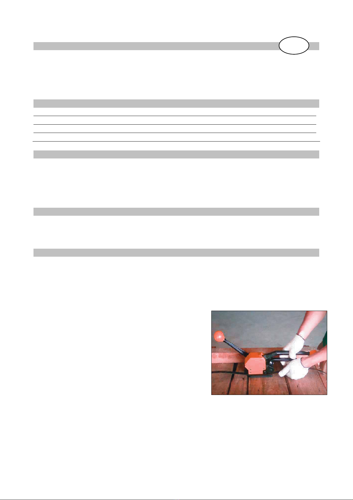
1. Aseta vanne kuorman ympärille ja pidä paikallaan
vasemmalla kädellä. Vanteen pään tulee olla
alimmaisena.
2. Vedä syöttökahvaa (58) kohti kiinnityskahvaa (73)
oikealla kädelläsi. Syötä vannetta työkalun sisään sen
seinämään asti niin, että vanne on sivupysäyttimen
sisäpuolella. Vanteen pään tulisi työntyö esiin
työkalun edestä noin 2 cm. Vapauta syöttökahva,
jolloin vanne lukkiutuu ja sitä voidaan kiristää.
FI

3
Syötä vannetta työkalun sisään sen seinämään asti.
Vanteen on oltava sivupysäyttimen sisäpuolella.
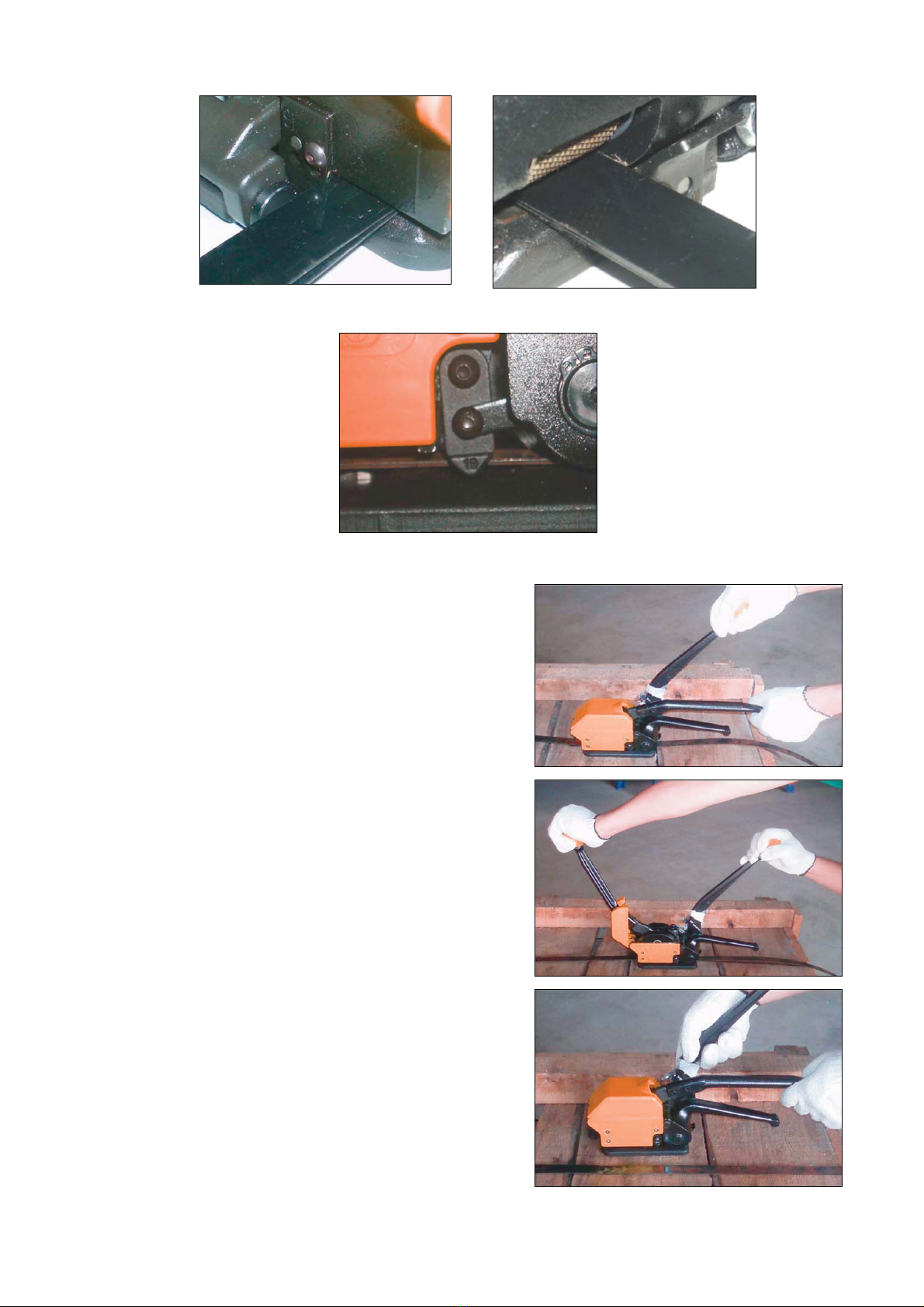
3. Pitele kiinnityskahvasta (73) tukevasti vasemmalla
kädellä. Painele kiristyskahvaa (82) edestakaisin
oikealla kädellä, kunnes haluttu kireys on saavutettu.
4. Tue työkalua pitelemällä oikealla kädellä
kiristyskahvasta (82). Työnnä kiinnityskahva (73)
kokonaan eteen pysäyttimeen (51) asti. Tämä
kiinnittää ja katkaisee vanteen.
5. Vedä kiinnityskahva (73) takaisin alkuasentoonsa.
Nosta syöttökahvaa (58) kiinnityskahvaa (73) kohden
vapauttaaksesi vanteen. Liu’uta työkalua oikealle,
jolloin se irtoaa vanteesta.

4
SÄÄTÖ
Kun vannetta aletaan kiinnittää, kaikkien pysäyttimien on oltava saman kokoiset.
13mm (1/2”)
16mm (5/8”)
19mm (3/4”)
Etupysäytin (13)
Sivupysäyttimet (91 ja 92)
Takapysäyttimet (36 ja 37)
Etu- ja takapysäyttimien säätö
Löysää ruuveja (14) työkalun edessä ja takana. Aseta haluttu pysäytinkoko paikalleen ja kiristä
ruuvit (14).
5
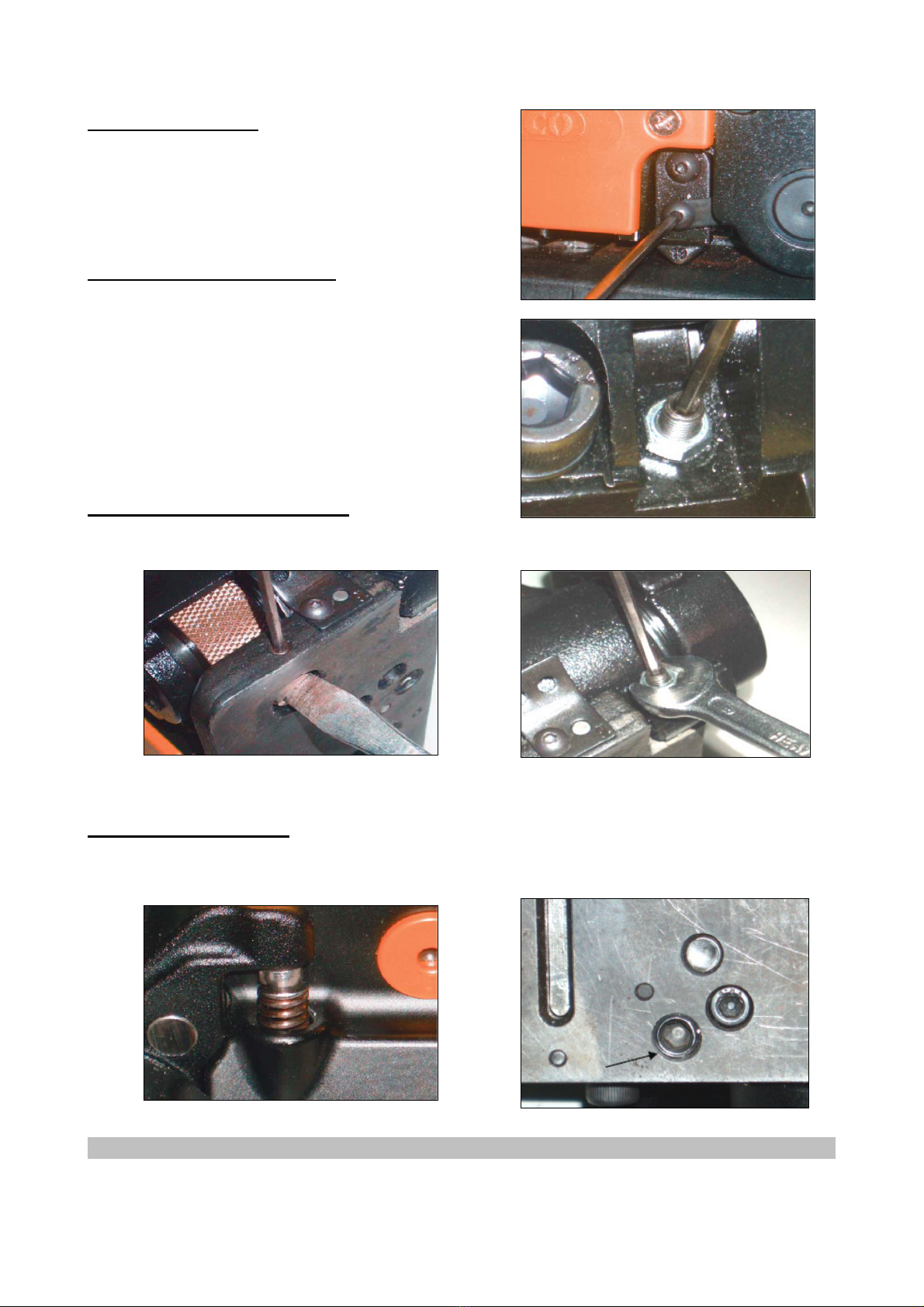
Sivupysäyttimen säätö
Löysää ruuveja (94 ja 14). Aseta haluttu pysäytinkoko
paikalleen ja kiristä ruuvit.
Kiinnityssauman syvyyden säätö
Löysää mutteria (52), käännä pysäytintä (51)
vastapäivään pienentääksesi kiinnitys- ja
leikkaussyvyyttä tai käännä myötäpäivään
kasvattaaksesi kiinnitys- ja leikkaussyvyyttä. Kiristä
lopuksi pysäytin ja mutteri.
Syöttöpyörän ja tarrainrulla säätö
Tämä säätö voi olla tarpeen vanteen lipsumisen välttämiseksi.
Tarrainrulla Syöttöpyörä
Syöttöpyörän jousen säätö
Kierrä ruuvia (15) kiintoavaimella myötäpäivään parantaaksesi tartuntatehoa.
6
Congratulations for choosing this high-quality equipment! We hope it will be of great help to you.
Remember to read the instruction manual before using the equipment for the first time in order to
ensure safe usage. If you have any doubt or problems, please contact your dealer or the importer.
We wish you safe and pleasant work with this equipment!
SPECIFICATIONS
Strap widths 13mm (1/2”), 16mm (5/8”), 19mm (3/4”)
Strap thickness 0,38mm (0,015”) – 0,58mm (0,023”)
Paino 3,5kg
SAFETY INSTRUCTIONS
1. Always wear eye, face and hand protection when operating this tool.
2. Do not put hands or other parts of the body between the strap and the package.
3. Use the original replacement parts to ensure its reliability.
4. Always read operating instructions before use.
MAINTENANCE
1. Clean this tool periodically with compressed air to remove any dust or dirt.
2. Apply light machine oil to all moving parts.
OPERATION INSTRUCTIONS
Prior to operation, make sure the front strap stop (13), side strap stop (91 for 16mm and 19mm, 92
for 13mm and 19mm), and rear strap stop (36 for 16mm and 19mm, 37 for 13mm and 16mm) are
equivalent to your strap width. (See ADJUSTMENTS for installation of strap stops).
1. Place strapping around the package and hold in place
with left hand. The end of strap is underneath.
2. Pull the feedwheel handle (58) toward the sealing
handle (73) with your right hand. While in this position,
insert the strap into the sealing section against the wall
of housing so the strap seat inside the sidestrap stop.
The end of strap should protrude approx. 2cm (1”)
beyond the front strap stop (13). Release the feedwheel
handle (58) so the strap is locked and ready to be
tightened.
EN
7
Insert the strap into the sealing section against the wall of housing.
Strap must seat inside the side strap stop.
3. Hold the sealing handle (73) firmly with left hand.
Pump the tension handle (82) with your right hand
until the desired tension is reached.
4. Place right hand firmly on the tension handle (82) for
supporting the tool. Push the sealing handle (73) all
the way forward until it reaches the stop (51). This
seals and cuts the strap.
5. Pull the sealing handle (73) back to its original
position. Lift the feedwheel handle (58) toward the
sealing handle (73) to release the strap. Slide the tool
away to the right.

8
ADJUSTMENTS
All front, side and rear strap stops must in the same number prior to use.
13mm (1/2”)
16mm (5/8”)
19mm (3/4”)
Front strap stop (13)
Side strap stop (91 and 92)
Rear strap stop (36 and 37)
Adjusting front and rear strap stops
Loosen screws (14) in front of and behind the housing. Put the size you want in place and tighten
the screws (14).

9
Adjusting side strap stop
Loosen screws (94 and 14). Put the size you want in
place and tighten the screws.
Adjusting sealing depth
Loosen nut (52), turn stop (51) counter clockwise to
decrease sealing depth and cutting depth, or turn
clockwise to increase sealing depth and cutting
depth, then re-tighten the stop (51) and nut (52).
Adjusting gap between feedwheel and gripper
It might be necessary to adjust the gap between the feedwheel (59) and the gripper (8) to prevent
slippery of strap.
Gripper Feedwheel
Adjusting feedwheel spring (56)
Turn the screw (15) with hexagon key clockwise to increase gripping performance.

10
RÄJÄYTYSKUVA JA OSAT ●EXPLODED VIEW AND PARTS
Nro Kuvaus Kpl Nro Kuvaus Kpl
1 Alusta 1 47 Jousi 1
2 Kiila 2 48 Holkki 1
3 Kiila 1 49 Sivulevy 1
4 Kuusiokoloruuvi 3 50 Ruuvi 3
5 Ruuvi 2 51 Pysäytin 1
6 Kuusiokoloruuvi 1 52 Mutteri 2
7 Pultti 1 54 Ruuvi 2
8 Tarrainrulla 1 55 Aluslevy 2
10 Lävistin 1 56 Syöttökahvan jousi 1
11 Ruuvi 1 58 Syöttökahva 1
12 Kuusiokoloruuvi 3 59 Syöttöpyörä 1
13 Etupysäytin 1 60 Akseli 1
14 Ruuvi 2 61 Kiila 1
15 Kuusiokoloruuvi 1 62 Ohjain 1
17 Leikkurin kannatin 1 64 Aluslevy 1
19 Rulla 1 66 Pidätysrengas 1
20 Kiila 2 67 Pidätysrengas 1
21 Vastin 1 69 Pultti 1
22 Vastin 1 70 Kiila 1
23 Yhdyslevy 1 71 Kuusiokoloruuvi 1
24 Ruuvi 4 73 Kiinnityskahva 1
25 Leikkuri 1 75 Nokka 1
27 Kiila 1 76 Kiila 1
31 Työnnin 1 80 Välilevy 2
32 Painejousi 1 82 Kiristyskahva 3
34 Ruuvi 2 84 Aluslevy 1
36 Takapysäytin (16/19 mm) 1 91 Sivupysäytin (16/19 mm) 1
37 Takapysäytin (13/16 mm) 1 92 Sivupysäytin (13/16 mm) 1
39 Runko 1 93 Holkki 1
41 Tappi 1 94 Ruuvi 1
42 Kiila 2 95 Kiila 1
45 Suojus 1 96 Ruuvi 1
46 Kiila 1
No. Description Q’ty No. Description Q’ty
1 Base 1 47 Cover spring 1
2 Pin 2 48 Bushing 1
3 Pin 1 49 Side plate 1
4 Socket set screw 3 50 Screw 3
5 Screw 2 51 Stop 1
6 Socket set screw 1 52 Nut 2
7 Bolt 1 54 Screw 2
8 Gripper 1 55 Washer 2
10 Punch 1 56 Feedwheel handle spring 1
11 Screw 1 58 Feedwheel handle 1

11
12 Socket set screw 3 59 Feedwheel 1
13 Front strap stop 1 60 Tension shaft 1
14 Screw 2 61 Key 1
15 Socket set screw 1 62 Strap guide 1
17 Cutter support 1 64 Washer 1
19 Roller 1 66 Retaining ring 1
20 Pin 2 67 Retaining ring 1
21 Die 1 69 Bolt 1
22 Die 1 70 Pin 1
23 Link 1 71 Socket set screw 1
24 Screw 4 73 Sealing handle 1
25 Cutter 1 75 Cam 1
27 Pin 1 76 Pin 2
31 Ejector 1 80 Shim 3
32 Pressure spring 1 82 Tension handle 1
34 Screw 2 84 Washer 1
36 Rear strap stop (16/19 mm) 1 91 Side strap stop (16/19 mm) 1
37 Rear strap stop (13/16 mm) 1 92 Side strap stop (13/16 mm) 1
39 Housing 1 93 Bushing 1
41 Trunnion 1 94 Screw 1
42 Pin 2 95 Pin 1
45 Cover 1 96 Screw 1
46 Pin 1

12

13
EY-VAATIMUSTENMUKAISUUSVAKUUTUS
Isojoen Konehalli Oy
Keskustie 26, 61850 Kauhajoki As
Suomi
vakuuttaa täten, että
VANNEKIRISTIN
malli nro. XK6071
on konedirektiivin no. 98/37/EY mukainen.
Mikäli tuotteen teknisiä ominaisuuksia tai käyttöominaisuuksia
muutetaan ilman valmistajan suostumusta, tämä vakuutus
lakkaa olemasta voimassa.
Päiväys: 11.02.2009
Allekirjoitus:
____________________
Harri Altis - Ostopäällikkö
CE-DECLARATION OF CONFORMITY
Isojoen Konehalli Oy
Keskustie 26, 61850 Kauhajoki As
Finland
herewith declares that
STEEL STRAPPING TOOL
Model no. XK6071
is in conformity with the Machinery Directive no. 98/37/EC.
This declaration is not anymore valid if the technical features
or other features of the tool are changed without
manufacturer’s permission.
Date: 11.02.2009
Signature:
____________________
Harri Altis - Purchase Manager
Table of contents
Languages:
Popular Packaging Equipment manuals by other brands


AirSaver
AirSaver F2 Safety instructions, setup & installation manual

HUALIAN
HUALIAN M-PE Series Operation manual

Pro Pack Solutions
Pro Pack Solutions Eagle 710 Operation manual

Oliver
Oliver 1808-D User's operation

Kronos
Kronos H-46 Series Operation, safety and spare parts manual

Robopac
Robopac ROBOT S7 Use and maintenance manual