12/12/2018
5
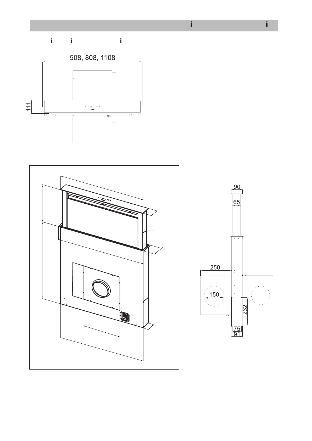
2 Unpacking and Installation
hood.
-Cleaning the hood with agents or devices
purpose, e.g. with a steam cleaner
( Maintenance).
- Repair work carried out by unauthorized
personnel ( Customer Service).
WARNING!
Verbrennungsgefahr. Bei falschem Betrieb
der Dunstabzugshaube kann es zu Verbren-
nungen kommen.
Risk of burns. Incorrect operation of the hood
can cause burns.
- Duly comply with the maintenance and
cleaning instructions
Basically refrain from:
1.5 Fire hazard
WARNUNG!
Stromschlag. Die Dunstabzugshaube wird
mit elektrischem Strom betrieben. Bei
falscher Montage, Handhabung und Betrieb
kann es zu schweren oder tödlichen Ver-
letzungen kommen. Sicherheitshinweise
beachten.
1.6 Power Supply
5
2 Unpacking and Installation
hood.
-Cleaning the hood with agents or devices
purpose, e.g. with a steam cleaner
( Maintenance).
- Repair work carried out by unauthorized
personnel ( Customer Service).
WARNING!
Verbrennungsgefahr. Bei falschem Betrieb
der Dunstabzugshaube kann es zu Verbren-
nungen kommen.
Risk of burns. Incorrect operation of the hood
can cause burns.
- Duly comply with the maintenance and
cleaning instructions
Basically refrain from:
1.5 Fire hazard
WARNUNG!
Stromschlag. Die Dunstabzugshaube wird
mit elektrischem Strom betrieben. Bei
falscher Montage, Handhabung und Betrieb
kann es zu schweren oder tödlichen Ver-
letzungen kommen. Sicherheitshinweise
beachten.
1.6 Power Supply
Any intervention by unauthorized personnel
terminates the guarantee and warranty claims
1.7 Defective equipment ATTENTION!
Do not install or operate a defective hood.
personnel authorized by the manufacture
( Customer Service).
2 Unpacking and Installation