iLoq D5S SB Series User manual

1. Content ................................................................................................................... 2
2. Safety Information.................................................................................................. 3
2.1 Safety signs .................................................................................................... 3
3. Overview ................................................................................................................. 3
4. Before installation .................................................................................................. 3
4.1 Mandatory precautions ................................................................................. 3
4.2 General notes................................................................................................. 4
4.3 Manufacturers involvement .......................................................................... 5
5. Installation .............................................................................................................. 6
5.1 iLOQ D5S.1XX series..................................................................................... 6
5.2 iLOQ D5S.2XX series..................................................................................... 7
5.3 iLOQ D5S.3XX series..................................................................................... 9
5.4 iLOQ D5S.4XX series..................................................................................... 11
5.5 iLOQ D5S.7XX series..................................................................................... 12
6. Removing and installing the electronic knob ...................................................... 13
7. Cylinder extensions................................................................................................ 16
7.1 One side - Version 1 ...................................................................................... 16
7.2 One side - Version 2 (5-15 mm) .................................................................... 19
7.3 One side - Version 2 (20 - 30 mm) ................................................................ 21
7.4 One side - Version 2 (35 - 70 mm) ................................................................ 24
7.5 Both sides....................................................................................................... 27
7.6 Long neck....................................................................................................... 27
8. After installation ..................................................................................................... 28
9. Disposal of decommissioned products................................................................ 29
10. Compliance ............................................................................................................ 30
1. Content
2
Document ID - 300598
iLOQ 5 Series (iLOQ D5S.XXX(A).SB, D5S.XXX.(L).SB)

2. Safety Information
2.1 Safety signs
Sign Description
General notice sign. Indicates particularly important information about the
installation or product.
Read these instructions carefully before using products. This information is to
ensure your safety and long lifetime of the products.
3. Overview
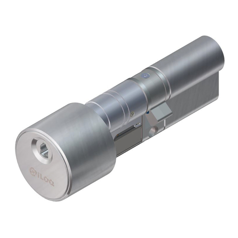
iLOQ D5S Europrofile Lock Cylinders are battery-free digital lock cylinders for the iLOQ S5 locking system.
The iLOQ D5S Lock Cylinders are powered with the energy from the motion of inserting the key into the
lock cylinder. This eliminates the need for any type of batteries or cabling.
4. Before installation
4.1 Mandatory precautions
• These instructions and any maintenance instructions should be passed on by the installer to the user.
If there are any deviations from the contents in foreign language versions of the documentation, the
English original shall apply in case of doubt.
• iLOQ D5S cylinders must be installed and used carefully without excessive force.
• Do not modify the product in any way, except in accordance with the modifications described in these
instructions.
• It is not allowed to uninstall or alter the anti-panic mechanism in any way. The functionality of the
mechanism cannot be guaranteed if it has been tampered with.
• Only use the cylinders for the purpose of opening and locking doors, any other use is not permitted.
• The key is to be kept secure so that only an authorized person can use it.
• If a key is lost, blocklisting of the lost key shall be done with the iLOQ Manager software and affected
locks shall be reprogrammed.
3
Document ID - 300598
iLOQ 5 Series (iLOQ D5S.XXX(A).SB, D5S.XXX.(L).SB)

4.2 General notes
• The iLOQ cylinders are successfully tested according the EN 1634-1 (EUFI29-19003368) for 120
minutes in a hinged single leaf steel door.
• Where the D5S cylinder is manufactured in more than one size, make sure that you select the correct
size.
• Make sure that any seals or weather-stripping fitted to the complete door assembly, does not inhibit
the correct operation of then D5S lock cylinder.
• Make sure that no projection of the D5S cylinder and associated parts can prevent the door from
swinging freely.
• Fit all components necessary for the specific installation in order to ensure compliance with EN15684
standard.
• The cylinder must protrude less than 1 mm on outside of the door to ensure proper operation.
• Before fitting D5S cylinder to a fire/smoke resisting door, examine the fire certification to ensure
conformity. Consult an iLOQ sales representative for the correct configuration.
• To extend the cylinder length, only use the associated D5 cylinder extensions (AD5.Exx).
• The incorrect type of cylinder can block or hinder the panic mechanism of the panic mortise
locks. Make sure that the anti-panic cylinder (D5S.7xx) is installed. Do not use other cylinder
types (D5S.1xx/2xx/3xxx etc.) unless you have made sure the lock type does not need a specific
cam position and the cam cannot block the panic functionality. Confirm the information from the
declaration of conformity provided by the mortice lock manufacturer.
• After installation, make sure that all parts of the lock are in an operational condition. When the D5S
lock cylinder is used in combination with panic locks, make sure the panic function of the mortise lock
is operational and cannot be hindered.
• The long neck versions have specially been developed for doors that do not have a Euro-profile cut
out inside the door frame resp. escutcheon/cylinder ring but only has a round hole.
• Use as a spare part only the article “A5.001”, and it is mandatory to mount the provided IP cover.
• Disposal of an RTC (Real Time Clock) into fire or a hot oven, or mechanically crushing or cutting of an
RTC can result in an explosion.
• Leaving an RTC in an extremely high temperature surrounding environment can result in an explosion
or the leakage of flammable liquid or gas.
• An RTC subjected to extremely low air pressure may result in an explosion or the leakage of
flammable liquid or gas.
• To meet the German VdS (VdS Schadenverhütung GmbH) requirements class BZ+ on burglary
threatened doors use a D5S.XX0A.SB high security cylinder installed with a VdS approved security lock
furniture of class B or C. Such security lock furniture corresponds to DIN 18 257 class ES 2 and ES 3.
• To meet the Dutch SKG*** requirements use a D5S.XXXA.SB high security cylinder. Consult an iLOQ
sales representative for correct configuration.
• Especially in industrial areas or near the sea, impurities can cause deposits in the form of rust and
attacked the material. This equipment should be cleaned and maintained frequently.
• For security reasons, the cylinder will lock itself after 10-12 seconds. The key can then be removed.
Turn the key back to the 12 o’clock position (either clockwise or anti-clockwise) and pull it out.
• After 5-10,000 usages, clean the contact rolls lightly with a lint-free cotton pad. Spray a small amount
of high-quality lock oil i.e. CRC lock oil (with PTFE) onto the contact rolls.
• If the cylinder is not functioning properly, clean the cylinder with e.g. compressed air spray or similar.
4
Document ID - 300598
iLOQ 5 Series (iLOQ D5S.XXX(A).SB, D5S.XXX.(L).SB)
4.3 Manufacturers involvement
No liability is accepted for damage to the doors or components due to incorrect installation. We reserve
the right to make modifications or further technical developments without further notice.
5
Document ID - 300598
iLOQ 5 Series (iLOQ D5S.XXX(A).SB, D5S.XXX.(L).SB)
5. Installation
5.1 iLOQ D5S.1XX series
1. Slide the lock cylinder into the lock case.
Make sure that the cam is pointing downwards.
2. Secure the cylinder to the lock case with an iLOQ fixing screw (A10.64, part of the delivery).
Use a tightening torque of 0.9 ...1.1 Nm. If necessary, cut the screw to the correct length (calculation
screw length: L = backset + 10 mm).
NOTE! Make sure that
the cylinder frame is a
maximum of 1.0 mm
from the door leaf or
escutcheon.
6
Document ID - 300598
iLOQ 5 Series (iLOQ D5S.XXX(A).SB, D5S.XXX.(L).SB)
Max. 1.0 mm

5.2 iLOQ D5S.2XX series
1. Detach the electronic knob from the lock cylinder as described in section “6. Removing and installing
the electronic knob.”
2. Slide lock cylinder into the lock case.
Make sure that the cam is pointing downwards.
3. Secure the cylinder to the lock case with an iLOQ fixing screw (A10.64, part of the delivery).
Use a tightening torque of 0.9 … 1.1 Nm. If necessary, cut the screw to the correct length (calculation
screw length: L = backset + 10 mm).
7
Document ID - 300598
iLOQ 5 Series (iLOQ D5S.XXX(A).SB, D5S.XXX.(L).SB)
4. Install the electronic knob as described in chapter “6. Removing and installing the electric knob”.
NOTE! Make sure that
the cylinder frame is a
maximum of 1.0 mm
from the door leaf or
escutcheon.
8
Document ID - 300598
iLOQ 5 Series (iLOQ D5S.XXX(A).SB, D5S.XXX.(L).SB)
Max. 1.0 mm

5.3 iLOQ D5S.3XX series
1. Slightly loosen the fixing screw of the turn knob with a 2 mm Allen key (counter-clockwise).
Loosen the fixing screw just enough to be able to remove the knob, do not remove it completely.
2. Slide the lock cylinder into the lock case.
Make sure that the cam is pointing downwards.
9
Document ID - 300598
iLOQ 5 Series (iLOQ D5S.XXX(A).SB, D5S.XXX.(L).SB)
3. Secure the cylinder to the lock case with an iLOQ fixing screw (A10.64, part of the delivery).
Use a tightening torque of 0.9...1.1 Nm. If necessary, cut the screw to the correct length (calculation
screw length: L = backset + 10 mm).
4. Insert the turn knob into place and tighten the fixing screw (clockwise).
Use a tightening torque of 1.5 Nm.
NOTE! Make sure that
the cylinder frame is a
maximum of 1.0 mm
from the door leaf or
escutcheon.
10
Document ID - 300598
iLOQ 5 Series (iLOQ D5S.XXX(A).SB, D5S.XXX.(L).SB)
Max. 1.0 mm

5.4 iLOQ D5S.4XX series
1. Slide the lock cylinder into the lock case.
Make sure that the cam is pointing downwards.
2. Secure the cylinder to the lock case with an iLOQ fixing screw (A10.64, part of the delivery).
Use a tightening torque of 0.9...1.1 Nm. If necessary, cut the screw to the correct length (calculation
screw length: L = backset + 10 mm).
NOTE! Make sure that
the cylinder frame is a
maximum of 1.0 mm
from the door leaf or
escutcheon.
11
Document ID - 300598
iLOQ 5 Series (iLOQ D5S.XXX(A).SB, D5S.XXX.(L).SB)
Max. 1.0 mm

5.5 iLOQ D5S.7XX series
1. Slide the lock cylinder into the lock case.
Make sure that the cam is pointing downwards.
2. Secure the cylinder to the lock case with an iLOQ fixing screw (A10.64, part of the delivery).
Use a tightening torque of 0.9...1.1 Nm. If necessary, cut the screw to the correct length (calculation
screw length: L = backset + 10 mm).
Max. 1.0 mm
NOTE! Make sure that
the cylinder frame is a
maximum of 1.0 mm
from the door leaf or
escutcheon.
NOTE! According to
standards EN179/
EN1125 it is
recommended to
regularly verify the
correct and faultlessly
functionality of a panic
door.
12
Document ID - 300598
iLOQ 5 Series (iLOQ D5S.XXX(A).SB, D5S.XXX.(L).SB)
6. Removing and installing the electronic knob
In some installation locations it is necessary to remove the electronic knob from the lock cylinder. Follow
these instructions to remove the knob. Re-install the electronic knob in the opposite order.
Be careful when inserting the knob not to break the connections on the cylinder. The removal of the knob is
only possible for people who have access rights to the cylinder.
1. Insert a key with the appropriate access rights into the lock cylinder and turn the key approx. 45
degrees clockwise.
After turning the key, the blocker hatch will open automatically at the bottom of the outside knob.
The hatch protects the fixing screw from unauthorized access.
2. Use a Torx T6 tool to loosen the fixing screw.
Do not remove the fixing screw completely, only loosen it just enough to be able to remove the knob.
13
Document ID - 300598
iLOQ 5 Series (iLOQ D5S.XXX(A).SB, D5S.XXX.(L).SB)
45 °

3. Remove the cover cup.
4. Remove the side screw counterclockwise with a Torx T6 tool and carefully detach the knob with the
PCB.
14
Document ID - 300598
iLOQ 5 Series (iLOQ D5S.XXX(A).SB, D5S.XXX.(L).SB)
5. Loosen the back-plate screw with a Torx T6 tool.
Do not remove the screw completely, only loosen it just enough to be able to turn the back plate.
6. Rotate the backplate counterclockwise and pull it off.
15
Document ID - 300598
iLOQ 5 Series (iLOQ D5S.XXX(A).SB, D5S.XXX.(L).SB)
7. Cylinder extensions
The cylinder length is easily adjustable in 5 mm increments from 30 mm (basic length) to 100 mm with the
extension piece system.
One extension piece can be added to both sides of the cam for the following cylinders:
• D5S.2xx > Double cylinder
• D5S.3xx > Knob cylinder
• D5S.4xx > Cylinder with dummy inside
The iLOQ D5S.1xx can only be extended on the knob side.
The iLOQ D5S.7xx.SD anti-panic cylinders are only provided in a set length due to safety reasons. The
length cannot be adjusted.
7.1 One side - Version 1
1. Remove the three body fixing screws with a Torx T6 tool and set the screws aside for later use.
NOTE! It is not possible to chain multiple extension pieces. Only one extension piece
on each side can be installed.
16
Document ID - 300598
iLOQ 5 Series (iLOQ D5S.XXX(A).SB, D5S.XXX.(L).SB)

2. Pull the lock cylinder modules apart.
3. Slide the shaft into the lock unit and make sure that the seal is in the correct place. Secure the
extension assembly with the provided screw. Use a Torx T10 tool (tightening torque 2.5 Nm).
Make sure that the black O-ring is between the extension assembly and the lock unit.
Make sure that the housing is aligned correctly.
NOTE! Make sure
that the O-ring is not
damaged. If needed,
replace with a new one
(spare part kit available
“A5.005”).
NOTE! Make sure
that the assembly
of the cylinder
extension is done in
a dry environment.
NOTE! Make sure
that the assembly
(cylinder housings) is
aligned straight.
17
Document ID - 300598
iLOQ 5 Series (iLOQ D5S.XXX(A).SB, D5S.XXX.(L).SB)
4. Secure the extension assembly with the provided screw.
Use a Torx T10 tool (tightening torque 2.5 Nm).
5. Slide the assembly with the backbone into the assembly with the extension piece and align the
housings.
6. Secure the lock unit with the three body fixing screws set aside earlier.
Use a tightening torque of 0.55 … 0.65 Nm.
18
Document ID - 300598
iLOQ 5 Series (iLOQ D5S.XXX(A).SB, D5S.XXX.(L).SB)
7.2 One side - Version 2 (5-15 mm)
1. Remove the three body fixing screws with a Torx T6 tool and set the screws aside for later use.
2. Pull the lock unit modules apart.
19
Document ID - 300598
iLOQ 5 Series (iLOQ D5S.XXX(A).SB, D5S.XXX.(L).SB)

3. Slide the shaft into the lock unit and make sure that the seal is in the correct place. Secure the
extension assembly with the provided screw. Use a Torx T10 tool (tightening torque 2.5 Nm).
4. Slide the assembly with the backbone into the assembly with the extension piece and align the
housings.
5. Secure the lock unit with the three body fixing screws set aside earlier.
Use a tightening torque of 0.55 … 0.65 Nm.
NOTE! Make sure
that the assembly
(cylinder housings) is
aligned straight.
NOTE! Make sure
that the conical seal
is in place before
assembly.
NOTE! Make sure
that the assembly
of the cylinder
extension is done in
a dry environment.
20
Document ID - 300598
iLOQ 5 Series (iLOQ D5S.XXX(A).SB, D5S.XXX.(L).SB)
This manual suits for next models
9
Table of contents
Other iLoq Lock manuals

iLoq
iLoq S50 User manual

iLoq
iLoq D50S.531.SB Installation guide

iLoq
iLoq P55S.1 User manual

iLoq
iLoq C10S User manual

iLoq
iLoq K55S User manual

iLoq
iLoq H50S.31.HC Series Installation guide

iLoq
iLoq S50 User manual

iLoq
iLoq D50S Series Installation guide

iLoq
iLoq G50S.2x1 Installation guide

iLoq
iLoq S10 User manual