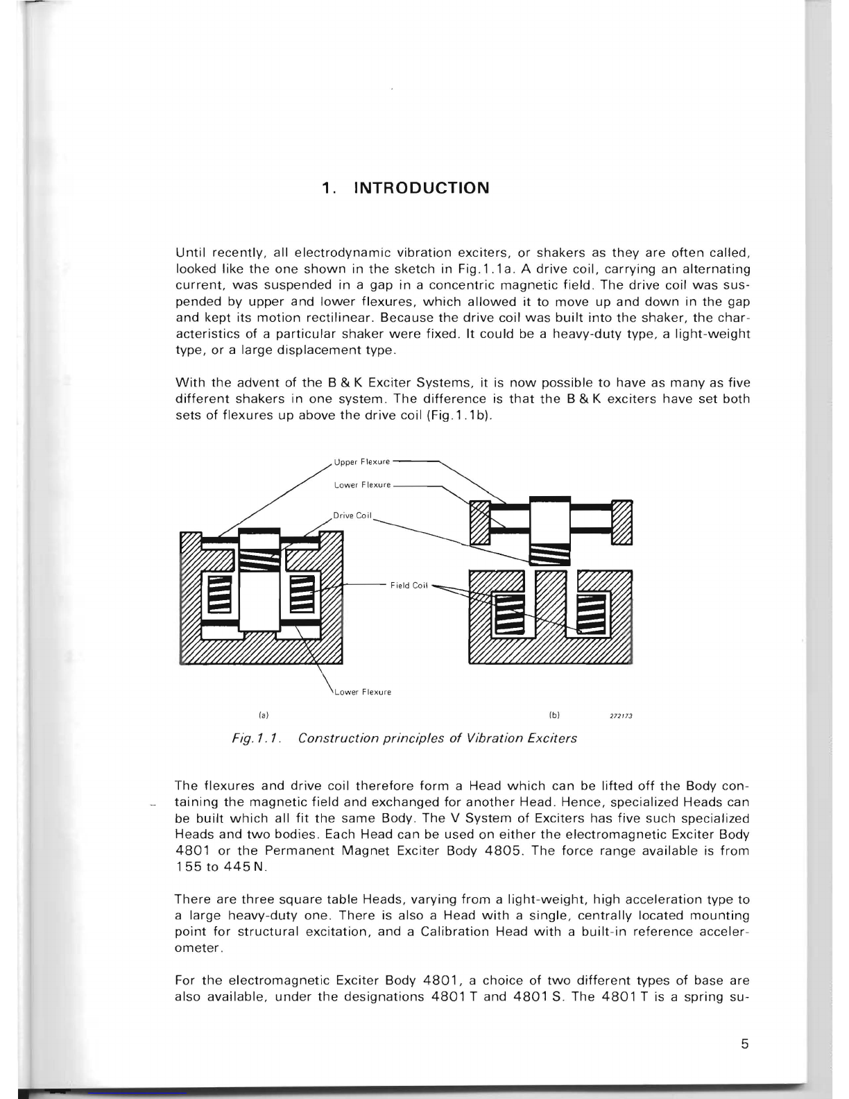
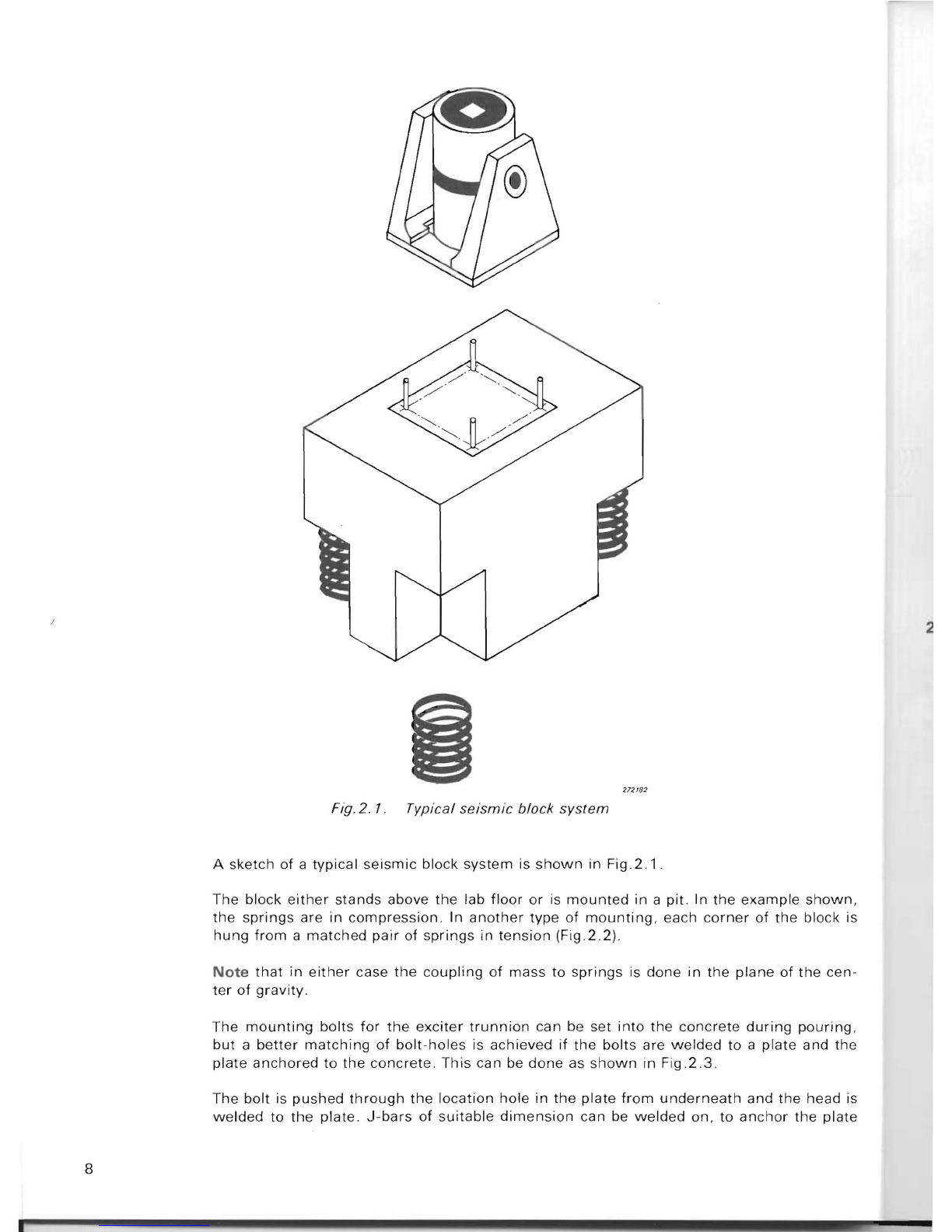
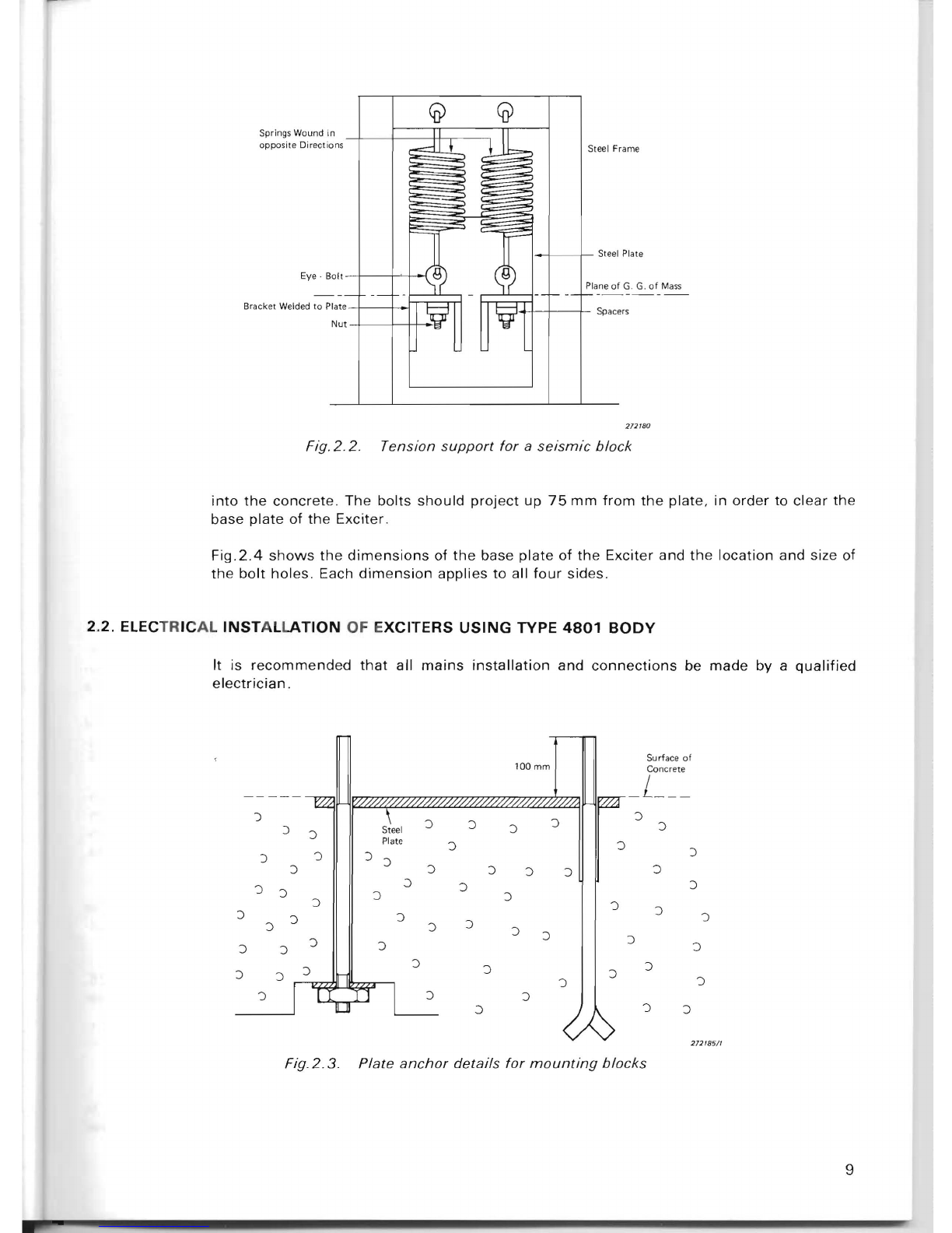
BRUEL & KJAER System V User manual

Arco..a E'E,crGrlkr,
s
:
ori
;;~
a
=:ren
lna
vvww.
aef
.se -
Instruction
Manual
Vibration Exciter System V
• Exciter Body
Type
4801
with
General Purpose
Head Type
481
2
•
High
g Head
Type
4811
•
Mode
Study
Head
Type
4814
•
Permanent
Magnet
Body Type
4805
with
Calibration
Head Type
481
5
• Big Table Head
Type
4813
This
Vibration
Exciter System can be used
over a large range
of
conditions
for vibra-
tion
tests
of
instruments
and
structures
. It
consists
of
two
exciter bodies and five exci-
ter
Heads.
The
exciter
employed is
driven
by a Power
Amplifier
2707
and can deliver a peak
force
of
380
to
445
N
with
Body Type
4801
or
267
to
310
N
with
the Permanent
Magnet
Exciter Body Type
4805.
The Exci-
ter
is protected mechanicalIy and electri-
cally. Cooling
of
the Exciter is performed by
a
built-in
fan
in
the
ca
se
of
the
4801
and
by an externaI
extractor
fan (not supplied) in
the
case
of
the
4805
.
Any
angle
of
opera-
tion
through
360
0
may
be chosen, the body
being locked in position by a
handwheel
.
~
Bruel &
Kjcer
033-0070

VIBRATION
EXCITER
SYSTE
M V
EXCITER
BODY
4801
EXCITER
BODY
4805
HIGH
g
HEAD
4811
GENERAL
PURPOSE
HEAD
4812
BIG TABLE
HEAD
4813
MODE
STUDY
HEAD
4814
CAlIBRATION
HEAD
4815
(Applicable
to
4801
from
serial no.
807327)
Revision February
1980

CONTENTS
1.
INTRODUCTION
......
.
.............
..
...........
............ .. .......
..
.....
.
......
..
:................
...........................
5
2.
INSTALLATION
...........................
....
.
.......
.
........................
..........
......
...
.................................
7
2.1.
MECHANICAL
INSTALLATION
OF
EXCITERS USING
TYPE
4801
BODY .....
.............
...........
..............
.........
......
.........
........
......
7
Direct
Mounting
..
.............
.......
..
......
..
.....
.........
..
........
....
....
.............
......
7
Mounting
upon a
seismic
block................
............
..
.....
.. ..
.. ...
.....
...
.....
....
.. ..
7
2.2
. ELECTRICAL INSTALLATION OF EXCITERS USING
TYPE
4801
BODY
..........
..
................
......
..
................
..
..........
..... ..
...........
9
System
Interconnection
......
......
.
.........
..
..
........................
....
........
.. .....
.....
..
10
Fan
Motor
Fuses ..
..
...............
..
.......................
...
.......
....
......
..
.....
.......
.......
10
2 .3 . INSTALLATION
OF
EXCITERS USING
TYPE
4805
BODY
.................................................
....
...............
.. .. ..
12
3.
OPERATION
.....
..........
......
....
.
..........
.........
....
..........
..
......
.......................
.................
..
..
.....
....
13
3.1. PRINCIPLE
OF
OPERATIOI\J
.......
..
........
.....................
....
.....
..
..
..... .....
......
...
13
3.2
. SELECTION
OF
APPROPRIATE B & K EXCITER HEAD
...............
... ..
..
.........
13
Brief
Description
...........
...............................
.. .. ..
........
.........
......
..............
14
3.3.
MOUNTING
AND
REMOVAL
OF
EXCITER HEAD ...
..
...........
....
.. ..
............
..
..
15
4801
Body .
..............
.....
...........
......
......................
.......... ..............
..
........
15
4805
Body
...........................
...........
............
......
.............
.....................
16
3.4
. INSERT INSTALLATION
AND
REPLACEMENT
...
..
..........
.
............
.
..
.
......
16
3.5. FIXTURES
.......................................
..
......... .....
..
..
..............
..
.. .. ....
16
3.6.
MOUNTING
THE FIXTURE
AND
TEST OBJECT .............
..
.. .. .
.. ..
........
.. ........
..
17
Bolt
Patterns
and
Mounting
Screws
...
............
.....
.. .....
....
.......
....
..
.....
.........
17
Positioning
the
test
object
.......................................
..
..
.........
......
..
....
.. .
18
Externai
Supports
...............
.. ....
...............
....
.. ..
................
....
......
..........
.. ..
18
Electrical
connections
to
test
objects .
.......
...
..
.........
..
...........
.. ...
......
.
..........
19
3.7. POSITIONING THE EXCITER ....
...........
..
....
.. ...............
........
........
..
..............
19
3.8
. STATIC
LOAD
LIMITATIONS
.......
....
......
...
............
..
....
.
.......
.....
......
........
..
..
20
3.9.
PUSH RODS
.............................
.. ..... ....
.....
....
..............................
......
......
23
3.10.
START-UP PROCEDURE ...
........
...... .......
.......
.. .......
..
....... .....
........
.
......
....
24
3.11.
"EXCITER"
LAMP
INDICATION
...........................
...
.....
..
....
.
......
.
......
.. ..
..
....
25
3.12
. OPERATION
IN
HIGH
AMBIENT
TEMPERATURES ...
..........
..
......
................
25
4801
Body
.....
....
...............
.....
..
.... ....
.............
...... .
..........
........
........
25
4805
Body
........
..................................
.
.............
....
........
..
......
.. ...
....
......
25
3.
13.
REDUCTION
OF
RESIDUAL MOTION
.....
...
..........
.
....
...
.......
.
.............
..
....
.. . .
25
4.
DESCRIPTlON
OF
4801
EXCITER
BODy
...........
..
................
.....
...
....
.....
..............
......
...........
26
4.1.
THE
MAGNET
ASSEMBLy
..................
..
......
.. ..
....
......
.....
...
.....
....
.. ... ..
.....
...
27
Field Coils ....
..
..........................
..
............................
.......
..
........
.
..
...
....
...
..
27
Secondary
Bands
.. ......
..
... .
.. ..
.......... ..........
..
..
..
..
............
......
.. .. ..
....
..
........
27
Stem
............
.
..........
.. .. .
.....
..
..
.......
..
..
.......
...........
................
..
..
.
.............
27
Centre
Bowl
.. .
..
.............
.......
........
..............
......
..
...................
..
...............
27
Upper
Wheel
............
..
....
........
..........
.......
... ....
.....
......
.....
..................... ...
27

4.2. THE FIELD SUPPLY
AND
COOLlNG
ASSEMBLY
..
...... ....
......................
........
27
The
Head
and
Field
Cooling
Fan ..
..........
....... .
......
......
....
.........
.. ..
....... .. .....
28
Blower
Motor
.
......
..
....
..
.......
..
.
..
.......
........
.
..
.............
..
... ...
..
.....
.
..
...
........
.
..
29
Field
Supply
........
...
..
..
..
......
.. ..
...
..
.....
..
......
.....
..
............
........
..
......
.
..........
29
4.3
. EXCITER SUPPORT ...... ..
..
......... .... .. ..
................
...
.. ..
.. .. .. ..
.....
.. ... ...... ...... .
30
Base
......
..
..
........
......
.
.................
.. .
'"
.... .......
..
....
..
.... ..
......
.
......
...
........
.
..
30
Side
Supports
......
..
.
..
.................. ....
.....
...... ..
..
...
..
......
....
.. .....
..
...
.. .. ..
..
.... 30
Trunnion
Springs
..
......
..
..
..
..........
...
........
.....
........
....
..
.....
..
....
..
... .
30
High
Frequency
Suspension
Engagement
Knob
..
......
..........
30
Rotation
Bearing
/
Brake.
...........
......
..
......
........
..
......
..
30
Rotation
Clamp
Knob
..............
..
....
.. ..
........ ... ....
......
..
........
.. .. .. .....
..
...
....
. . 31
4.4.
4801
(S)
....................
.. .. .. .. .. ..
....
..
.......
..
...
....
.. .. ..... ..
.....
...
....
......
....
.....
31
5. PERMANENT M
AGNET
BODY
, TYPE 48
05
......
.. ....
....
...
..
.. .. ........
.......................
......
......
..
....
32
6.
DESCRIP
TION
OF EXCITER HE
ADS
......................
..
..........................
....
.....................
.
..
......
33
6.1.
HEADS WITH SQUARE TABLES, TYPES
4811,
4812,
4813
....
..
.
.......
........
..
33
Table and
Mounting
Surface
.................................................
........
.
.. ..
...... 33
Flexure
System
.
......
..
......
..
.
.............
.. .. ....
..........
.. .. ...
..
........
...
..............
.
33
Stray
Magnetic
Field ...
..
............
........
.. ..
..
..
...........
..
.. ...
..
..........
..
.. .. .. ..
35
M
echanic
al Ov
er-trave
I Stops ......
..
.............
..........
........
..
..........
............. ...
36
Split
Hub
..
..............
....
..
.
..
.........
..
........
..
....
.. ....
..
.
..
....
....
. .. ... . ... .
36
Driver
Coil
.........
.. 36
Side
Overload
Pads
......
37
Moving
Element
Skeleton
. .
..
......
.. .. .. ..
.....
.......
....
.
..
.....
.. ..
.. .......
....
....
..
..
.. 37
Boot . .
...........
... 38
Protective
Can
an
d Guidance
Pins
for
the
Head ..... ..
..
..........
.......
.............
..
38
6.2.
THE MO
DE
STUDY HEAD TYPE
4814
..
.....
.. .. ....
..
...
.......
..... ..... ... ...
..
........
.. .
38
6.3.
THE
CA
lI
BRATION HEAD
TY
PE
4815
.. .. ...
..
.. ... ... .. ....
..
.. .....
..
39
Reference
Accelerometer
.........
... ....
..
... ........
.. .. .. .. ..
.... ....
..
...........
.......
.
40
Mounting
the
Accelerometer
.. ..
...
..
4 1
Other
Features
Specific
to
the
Type
4815
42
7.
CHARACTERISTICS
...........
....
..
..
.
.......................
..
............
..
...................
..
..
.
..
.................
..
....
43
7.1.
S
QU
ARE TABLE
HE
ADS
.....................
..
..
.
....
.......
........
..
..
43
Frequency
Response and Resonance
..........
..
.
..
....
.. ....... .......
....
..
.. .....
......
...
43
Rated Force and
Limits
.......................
...
......
..
..
....
..
...
... .. .......
..
. ... .
..
..
.... . 44
7.2 .
MO
DE
STUDY
HE
AD
.................................
..
..
. ....
...
..
...
....
..
. 45
7.3.
CALlBRAT
ION
HEA
D TYPE
4815
..........
.
..
.
.....
......
.. ..
...........
..
....
...
..
.. .. ... .
49
Frequency
Response
of
the
Head
....................................
..
..
.. .........
....
.... .
49
Frequency
Response
of
the
Standard
Accelerometer
Type
8305
.........
..
...
..
. . 50
Acceleration
vs. Load .
...................
..
..........
.. ....
....
.
50
C
ross-Motion
..
. ... ... ......
................
..
..........
..
...
....
......
.... . 51
Errors
in
Ca
libration
..
.....
.. .. ..
.......
..
.........
..
...... .
.....
..
..
.......
................
51
8.
CARE
AND
MAINTENANCE
.............
...................................................................................
54
8
.1
. PERIODIC C
LE
ANING
...
........
.. ................. ..
..
...........
....
......
..........
......
..
...... 54
8.2
. CARE OF EXCITER BO
Dy
.. .......... .. ....... ... .......
........
..
....
..
......
..
..................
54
Exc
iter
Body Cover
..
.
.......
.
..
................... ............
....
.......... ... ...........
..
......
..
54
Clea
nli
ness
of
Exciter Body
..........
.. ..
..
..
....
.. .
.......
..
......
....
..
....
..
......
...
..
........
55

Field Coil
Cleaning
..........
.......
..
......
..
......
..
.....
.
....
.
.....
..... .................. .. ....
55
8.3.
CARE
OF
EXCITER HEAD
........
..
........
.. .
..
.....
....
....
.
........
....
......
..
.....
....
....
.
55
Removal
of
Cable ...
..
.
.....
..........
....
...
..
.. ......
....................
..
............
......
....
55
Cleaning
of
Exciter
Head
.. ..
......
..
.....
..
... .......
.......
....
.......
..
.......
........
.. ..
..
..
56
Clean
Workbench
Surface
..
..
..
.
..
......
.....
....
..
.... .. ..
..
.......
..
.....
....
.........
... ....
56
Care
of
Mounting
Surface
...
....
......
.. .. ...
.. .. ..
.........
....
......
... ...... ... .....
..
.. ....
56
Exciter Head
Inspection
and Repair ......
....
..............
.....
....
..
.......
.......
..... ....
56
8.4.
CARE
OF
EXCITER BODY
4805
......
....
.........
....... .. ......... .. .
....
.. ..
..
.. ..
........
56
9. SPECIF
ICA
TIO
NS
.................
......
........
..........
......................................................
.
........
...
..
..
57
9.1. EXCIT
ER
BODY
4801
..
....
...........
..
.......
......
..
.....
.....
..
....
.......
.....
..
.. ..
.....
...
57
4801
T ...
..
.............
......
.......
..
.
....
..
.. ..
.... ..
..
....
........
....
..
....
..
....
..
......
.....
...
57
4801
S
..
........... .....
........
................. .....
.....
.......
..
...
.. ..
.
..
........ ..........
..
....
57
9.2. EXCITER BODY
4805
..
.....
......
......
.......
....
........
.....
..
.......
..
....... .
..
............
58
9.3. EXCITER HEADS ..........
..
.
..
...
.....
..
......
..
.....
..
.....
..
.
......
............... ....
........
..
58
High g Head Type
4811
....
.............
...
..
..
..
.. ..........
.. ..
...
..
..
..
..........
........
.. ..
58
General
Purpose Head Type
4812
......
..
.......
...... .. .
..
.. ....
..
.. .........
..............
59
Big Table Head Type 48 13 ........ .
..
.....
...
..
...........
.........
.....
.. ..
.........
...
..
.....
60
Mo
de
Study
Head Type 48
14
.............
..
......
..
...
..
...
..
....
..
...
..
......
..
.............
61
Ca
libration
Head Type 4 8 15 ..
..
..
..
....
......
.
..
............
..
........
..
.......
....
..
.
..
.
.....
62
9.4
. NOTES TO SPECIFICATIONS .. ...
.. ..
....
.. ..
...
........
.............
..
...
.. ..
..
....
..
....
.. ..
62
9.5.
EXTERNAL
DIMENSIONS
....
...
..........
..
.
...........
....
......
...
.. .. ..
..... .. ..
....
..
..
63

1.
INTRODUCTION
Until
recently,
all
electrodynamic
vibration
exciters,
or
shakers
as
they
are
of
ten
called,
looked like
the
one
shown
in
the
sketch
in
Fig.1.1a.
A
drive
coil,
carrying
an
alternating
current.
was
suspended
in
a
gap
in
a
concentric
magnetic
field.
The
drive
coil
was
sus-
pended
by
upper
and
lower
flexures,
which
allowed
it
to
move
up
and
down
in
the
gap
and
kept
its
motion
rectilinear.
Because
the
drive
coil
was
built
into
the
shaker,
the
char-
acteristics
of a
particular
shaker
were
fixed.
It
could
be a
heavy-duty
type,
a
light-weight
type,
or
a
large
displacement
type
.
With
the
advent
of
the
B & K
Exciter
Systems,
it is
now
possible
to
have as
manyas
five
different
shakers
in
one
system.
The
difference
is
that
the
B & K
exciters
have
set
both
sets
of
flexures
up
above
the
drive
coil (Fig.1
.1
b)
.
Upper Flexure
---,
low
er Flexu
re
--_,
;::;il~~---
Field Coil
Lower
Flexure
la)
Ib)
272173
Fig. 1.
1.
Construction
principles
of
Vibration
Exciters
The
flexures
and
drive
coil
therefore
form
a Head
which
can
be
lifted
off
the
Body
con-
taining
the
magnetic
field
and
exchanged
for
another
Head.
Hence,
specialized Heads can
be
built
which
all
fit
the
same
Body
The
V
System
of
Exciters has
five
such
specialized
Heads
and
two
bodies.
Each Head
can
be used
on
either
the
electromagnetic
Exciter
Body
4801
or
the
Permanent
Magnet
Exciter
Body
4805.
The
force
range
available
is
from
155t0445N.
There
are
three
square
table
Heads,
varying
from
a
light-weight,
high
acceleration
type
to
a
large
heavy-duty
one.
There
is also a Head
with
a
single,
centrally
located
mounting
point
for
structural
excitation,
and
a
Calibration
Head
with
a
built-in
reference
acceler-
ometer.
For
the
electromagnetic
Exciter
Body
4801
, a
choice
of
two
different
types
of
base
are
also
available,
under
the
designations
4801
T and
4801
S. The
4801
T is a
spring
su-
5

spension
arrangement
which
provides
isolation
at
most
frequencies
and
has
the
facility
of
full
360
0
positioning
.
The
4801
S is a
simplified
base
upon
which
the
Exciter
is
fixed
in
one
position
.
Uniess
otherwise
stated,
in
this
book
the
4801
T is
the
Body
referred
to.
For
same
applications,
it
could
be
preferable
to
use a
Permanent
Magnet
Exciter
Body
4805.
It
has
the
advantage
of
quieter
operation
since
it
can
be
operated
without
cooling,
but
the
disadvantage
of
reduced
force
rating
. Use
of
the
permanent
magnet
bodies
re-
duces
the
power
available
to
70%
of
that
available
with
the
4801.
6

2.
INSTALLATION
2.1.
MECH
ANIC
AL
INSTALLATION
OF
EXCITERS
USIN
G
TYP
E
48
01 B
OD
Y
The
technique
used
to
install
the
Exciter
Body
4801
depends
upon
the
usage. For
most
applications
,
the
Base
of
the
exciter
may
be placed
directly
upon
the
floor.
For
more
criti-
cal
applications
,
other
mounting
techniques
may
be
preferred.
2.
1.1.
Dir
ect
Mo
untin
g
The
easiest
way
to
mount
the
Exciter
Body
4801
is
to
place
the
Base
directly
on
the
floor.
This
technique
is
suitable
whenever
the
forces
transmitted
from
the
exciter
to
the
floor
do
not
produce
objectionable
results
and
when
the
motions
coupled
to
the
exciter
from
the
floor
do
not
affect
the
usefulness
of
the
exciter.
Motion
transmitted
to
the
exci-
ter
through
its
body
is
likely
to
be
insignificant
for
operation
frequencies
over
30
Hz and
when
an
appreciable
fraction
of
the
available
force
is used.
The
forces
transmitted
to
the
building
are
seldom
bothersome
when
the
exciter
is placed
on
a
substantiai
masonry
floor.
If
the
exciter
is placed
on
a
thin
wooden
floor
,
the
forces
transmitted
from
the
exciter
to
the
building
are
likely
to
cause
annoyance
,
in
the
form
of
vibration
and
noise
. For
some
situations,
an
adequate
reduction
in
the
irritation
leveiover
that
obtained
with
direct
mounting
can
be
achieved
by
placing
an
inch
or
two
of
soft
re-
silient
material
under
each
corner
of
the
Base.
2.
1.2.
Mo
unting
upon
a seis
mic
block
Vibration
isolation
better
than
that
provided
by
the
trunnion
springs
of
the
exciter
usually
is
obtained
only
by use
of
a
seismic
block.
A
seismic
block
consists
of a large
mass,
typically
reinforced
concrete
supported
by a rel-
atively
soft
spring
system
. The
mass
is
typically
ten
times
as
large
as
the
mass
of
the
ex-
citer
itself.
Hence
the
block
characteristics
dominate
and
the
entire
complex
of
exciter
and
seismic
block
may
be
treated
as a
simple
mass
on
a
spring,
i. e., a
single
degree
of
freedom
system
.
Such
a
system
has
a
resonant
frequency
corresponding
to
f=_l_~
k
2TT
m
where
k
equals
the
overall
spring
stiffness
of
the
system
and m is
the
total
mass.
Since
the
mass
of
the
V
System
Exciter
is
about
85
kg
(187
Ib),
depending
on
which
head
is
chosen,
its
seismic
block
should
have a
mass
of
about
850
kg
(1870
Ib)
This
corre-
sponds
to
0,35
m3
(12,5
ft
3)
of
reinforced
concrete
.
If
the
Exciter
should
work
down
to
1 Hz,
then
the
spring
stiffness
of
the
suspension
system
should
be
k =
(2
TT)
2 m =
33,4
N/
mm
(190
Ib/ in)
7

272
182
Fig.2.
1.
Typical
seismic
block
system
A
sketch
of
a
typical
seismic
block
system
is
shown
in
Fig.2.1.
The
block
either
stands
above
the
lab
floor
or
is
mounted
in
a
pit.
In
the
example
shown,
the
springs
are
in
compression.
In
another
type
of
mounting,
each
corner
of
the
block is
hung
from
a
matched
pair
of
springs
in
tension
(Fig.2.2).
Note
that
in
either
case
the
coupling
of
mass
to
springs
is
done
in
the
plane
of
the
cen-
ter
of
gravity
.
The
mounting
bolts
for
the
exciter
trunnion
can
be
set
into
the
concrete
during
pouring,
but
a
better
matching
of
bolt-holes
is
achieved
if
the
bolts
are
welded
to
a
plate
and
the
plate
anchored
to
the
concrete.
This
can be
done
as
shown
In
Fig.2.3.
The
bolt
is
pushed
through
the
location
hole
in
the
plate
from
underneath
and
the
head is
welded
to
the
plate.
J-bars
of
suitable
dimension
can be
welded
on,
to
anchor
the
plate
8
2

-----
Springs Waund in
o
pp
osite Directi
ans
Eye · B
alt
Bracket
Wel
ded to Plate
Nut
--
(j})
.-dl
J
C
~
--
-
~
~
C{Y
]b
Steel Frame
~
:)
~
or
Steel
Plane
of
--
r---
- -
Pl
ate
G. G.
of
Mass
I----i
Sp
ac
V
ers
271180
Fig
.2.2. Tension
support
for
a
seismic
block
into
the
concrete
.
The
bolts
should
project
up
75
mm
from
the
plate,
in
order
to
clear
the
base
plate
of
the
Exciter.
Fig.2.4
shows
the
dimensions
of
the
base
plate
of
the
Exciter
and
the
location
and size of
the
bolt
holes.
Each
dimension
applies
to
all
four
sides.
2.2. ELECTR
IC
AL
INST
A
LLATION
OF E
XCITERS
USING
TYPE
4801
BODY
It is
recommended
that
all
mains
installation
and
connections
be
made
by a
qualified
electrician
.
S
urf
ace
of
100mm
Concrete
_L
___
")
J
J J J
) Steel J J
J
Pl
ate J J )
)
')
)
')
')
J
')
J
J J
')
')
')
J
J J
')
J
')
')
J
')
J
J J
J J J J J
J J
J J J
J J
J J
J J J
') ')
')
J
') ')
J
272185/1
Fig.2.3.
Plate
anchor
details
for
mounting
blocks
9

381
mm
(15 ini
l'
'I
I
---$--
-
--
-$-
--1-.
E
E
o
'"'
M
I
--
~
--
I
70 mm (2,75
ini
15
mm
(0.59 i
ni
212181
/ 1
Fig.2.4.
Bas
e
p/ate
dime
nsio
ns
for
4801
T
2.2.1.
System
Interconnection
The Type
4801
Exciter Body is
supplied
with
two
captive cables. One
of
these
is a five-
core cable,
which
carries
three-phase
mains
power
to
the
Exciter Body. It
includes
a
neu
-
tral
and an
earth
. The
other
is
the
safety
trigger
cable.
When
the
4801
is used
with
a
suitable
B & K
amplifier
such as Types
2707
or
2708,
this
cable is used
to
initiate
shut-
down
in
the
event
of
overheat
ing
of
the
field
coil, loss
of
a
supply
phase
or
blowing
of
one
of
the
fuses
on
the
safety
circuit
board.
Shutdown
includes
removal
of
both
the
exci-
tation
and
the
three-phase
supply f
rom
the
Exciter.
For
connection
of
these
cables
to
a B & K
Amplifier
Type
2707
or
2708
,
refer
to
the
in-
struction
manuals
for
these
instruments
.
If
the
4801
is
to
be
connected
to
an
older
am-
plifier
Type
2707
, having single-phase
power
requirements,
consult
your
B &K represen-
tative
. Remember
to
reduce CURRENT LIMIT
to
alevei
appropriate
to
the
head in use,
especially
with
the
more
powerfu
l
Amplifier
Type
2708
.
For
maximum
operating
safety
the
green
/
yellow
conductor
in
the
power
cable
must
be
connected
to
a
suitable
earth,
such as
the
protective
earth
contact
of
a mains socket
out
-
let. The use
of
extension
cables
without
protective
conductor
sha.1I
be avoided.
Connection
of
th
e Exciter Head
to
the
power
amplifier
is made via drive cable
AQ
0026
,
which
has a
3-pin
connector
at each end.
Either
end
may
be connected
to
the
Exciter
Head.
2.2.2
. Fan
Motor
Fuses
The
three
fan
-
motor
fuses
are
situated
on
the
safet
y
circuit
board.
To
gain
access to
them
remove
th
e base cover
of
the
Exciter,
which
is held
in
place by
four
screws.
See
lO

Fig .2.5. Details of
the
fuses are given in
the
Specifications.
Mak
e sure
that
only fuses
with
the
required rated cur
rent
and of
the
specified type are
us
ed
for
replace
me
nt. The
use
of
mended fuses a
nd
th
e sh
ort
-
circu
iti
ng
of
fus
e-holders is
prohib
it
ed.
F
an
Molor F
uses
11 A sl
ow·blowl
----,
Cab
le E
nlr
y
--
---
--,
Sa
fety
Cir
cuit
Board
Ea
rth
Fan
o
lor
---
;::;
8OOJ59
Fig.
2.5
.
Exciter
Body
with
base cover re
moved
2.3. INSTALLATION
OF
EXCITERS
USING
TYPE
4805
BODY
The cable
connection
between
the
Power
Amplifier
2707
and
the
Exciter Head is made
as in se
ction
2.2
. In
order
to
complete
the
electrical loop
which
operates
the
EXCITER
IN
-
TERLOCK, a
connection
must
also be made
from
the
Exciter Body back
to
the
Power
Am
-
plifier
For
this
reason a
single
conductor
cable has been provided
(AO
0103).
which
should
be
connected
as
shown
in Fig.2.6. The
banana
plug is
inserted
in
the
hole pro-
vided
in
the
4805
Body. On Power
Amplif
i
ers
wi
th
single
-phase
mains
supplies
the
tree
end is
connected
to
terminals
1
and
2
of
the
terminal
board. For
connection
to
Power
Amplifiers
with
3-phase
mains
supplies
,
refer
to
the
Instruction
Manual
for
the
Ampli
-
fier
.
Terminal Board
2707 740410
Fig 2.6. E
xciter
inter/ock
connections
for
4805
Body
11

In
order
to
get
the
maximum
power
possible
out
of
the
permanent
magnet
system
it is
necessary
to
supply
a cool
air
flowaround
the
drive
coil.
This
air
flow
should
be
0,42
m3 /
min
at
0,008
kg/cm
2
pressure.
An
ordinary
vacuum
cleaner
will
suffice
.
The
hole
in
the
base
of
the
PM Body is
made
to
receive
a
vacuum
cleaner
nozzle.
Note
that
the
vacuum
cleaner
should
be used
to
suck
air
from
the
Shaker
rather
than
blow
air
in.
The
air
blown
from
vacuum
cleaners
is
generally
t
oo
war
m
for
use
as a cool
ant.
It
should
also
be
noted
that
the
base
of
the
B
ody
is op
en.
Th
erefore
if
the
S
haker
is used
in
other
than
the
upright
position,
for
instance
if
it
is
sim
ply laid
on
its
side,
it
will
be
necessary
to
fix
a
plate
to
the
bottom
in
order
to
ensure
an
adequate
cooling
flow.
If
the
Shaker
is
suspended
by
using
a
plate
fixed
to
the
mounting
holes
in
the
bottom
(see sec-
tion
3.7)
then
there
is
no
problem
. Fig.
2.7
is a
bottom
view
of
the
4805,
showi
ng
the
placement
of
the
mounting
holes
.
~
121
± 0,2
~
83 ±
0,3
8 x
11
mm
~
Air
·holes
7404
12
Fig.2
.7.
Boltom
of
the
4805
12

3. OPER
ATION
3.1. PRINCIPLE OF
OP
ER
AT
ION
The
forces
generated
in
an
electrodynamic
exciter
are
due
to
the
interaction
between
an
alternating
current
in
a coil
and
a
magnetic
field.
This
is
illustrated
in
Fig.
3.1.
Test
Obj
ec
t
Signal
Source Power
Am
p
li
fi
er
1-------------,
211056
Fig.3
. 1.
Principle
of
operation
of
an
Electrodynamic
Exciter
, is
the
current
in
the
coi',
B
the
flux
density
of
the
magnetic
field
and
F
the
force
gener-
ated by
the
coil.
The
magnitude
of
the
force
is
given
by
F = BIL
where
F = Force
in
newtons
B =
Ma
gnetic
flux,
in
webers
I =
Current
in
coil,
amperes
L =
Length
of
conductor
in
magnetic
field,
metres
The
current
for
the
exciter
is
provided
by a
power
amplifier.
A
signal
source
,
such
as a
sine-wave
or
random
generator,
is
connected
to
the
input
of
the
amplifier.
As
the
signal
is
fed to
the
coil,
a
fluctuating
force
and
hence
a
vibratory
motion
is
imparted
to
the
test
ob-
ject.
Of
course,
the
coil
itself
is
wound
about
a
moving
element
and
this
has
a
certain
mass.
Hence
the
acceleration
due
to
an
applied
force
F
will
be
F
a m + me
where
m is
the
mass
of
the
test
object
and
me
is
the
moving
element
mass
.
3.
2. SELECTION
OF
APP
ROPRIATE
B & K EXCITER HE
AD
The
user
is
urged
to
read
the
detailed
specifications
for
each
of
the
currently
available
B & K
Exciter
Heads. He
should
select
the
Exciter Head
having
specifications
best
suited
to
his
p
articular
application.
A
brief
summary
of
typical
specifications
is
shown
in
Table
3.
1.
In Table 3.1
the
first
thr
ee
lines
list
the
force
a
vailabl
e
fro
m each
of
5 B &K E
xciter
13

B & K Exc
it
er Head
Ty
pes
4811 4812 4813
4814
4815
Force,
with
48
01
N
(Ibf
)
370
(85) 445 (100)
445
(100) 370 (85)
370
(85)
Force,
with
4805
and cooling N (Ibf) 248 (56)
310
(70) 283 (64) 267 (60) 267 (60)
Force,
with
48
05,
no cooling N (l
bf)
124 (28) 155 (35) 142 (3
2)
133 (30) 133 (30)
Moving Element
Ma
ss
Displacement
Limit
Resonant
Frequency
Mounting
Point
Locations
kg
(lb)
mm (in)
Hz
Circle,
Diameter
mm (in)
Square,
Side
mm (in)
0,18
(0,4)
13 (0,5)
8500
50,8
(0,2)
35,9
(1,414)
0,45
(1,0)
13 (0,5)
7200
76,2
(3,0)
53,9
(2,13)
0,79
(1
,6)
13 (0,5)
5400
114,3
(4,5)
80,8
(3,18)
0,23 (0,5)
25 (1,0)
64
00
Threaded
hole in
center
of
19 mm
(0,75)
diamet
er
tab
le
0,32 (0,7)
13 (0,5)
10000
Reference
accel
erometer
Table 3.
1.
V
System
Exciter
Heads
Heads
when
connected
to
the
4801
Body,
and
when
connected
to
the
4805
Body
with
and
without
cooling
.
This
force
is
the
force
F
described
in
Section
3.1
.
T
he
fourth
line
lists
the
mass
of
the
moving
elements
.
Exciter
Heads
4811,
4814
and
4815
are
wound
with
aluminum
wire
and
4812
and
4813
with
copper
wire
.
The
copper
winding
permits
greater
current
flow
per
cross-sectional
area and
therefore
greater
force
.
Use
of
the
aluminum
winding
lightens
the
total
moving
element
weight
. 3.3
The
fifth
line
lists
the
available
peak-to-peak
displacement.
A
displacement
of
13
mm
(0
,5 in) is
adequate
for
almost
all
environmental
vibration
testing
and
calibration
applica-
tions
.
The
larger
displacement
of
the
4814
is
useful
when
testing
structures
or
modeis.
3.3
The
sixth
line
lists
the
resonant
frequencies
of
the
moving
elements
. For
environmental
vibration
testing
and
calibration
applications,
operation
below
the
resonant
frequency
provides
low
distortion
and
low
cross
motion
.
Although
operation
at
frequencies
up
to
100
kHz is
possible,
the
available
force
is
considerably
reduced
.
Exciter
Heads
4811
,
48
12
and
4813
have
a
centre
m
ountin
g
insert
and
four
equally
spaced
outer
inserts
.
Line
seven
gives
both
the
dia
me
ter
of
the
circle
formed
by
the
four
outer
inserts
and
the
side
of
the
equivalent
square
.
3.
2.
2.
Brie
f D
escription
The
High
g Head Type
4811
has
an
380
N
(85
Ibf)
force
rating,
a
light-weight
moving
element
and
high
resonant
frequency
. It is
especially
weil
suited
to
the
environmental
vi-
bration
testing
of
small
objects,
either
to
very
high
vibratory
acceleration
levels
or
to
high
freq
uencies
.
The Big Table Head Type
4813
has
a
445
N
(100
Ibf)
force
rating,
a
large,
stift
table,
and
14

extra
strong
fle
xure
s,
to
resis
t
large
applie
d
mome
nt
s. E
nvironm
e
ntal
testi
ng
of
lar
ge
de-
vices,
of
unb
alance
d o
bjects,
and
of
objects
w
ith
se
vere
t
ransv
erse
resonances,
is b
est
don
e
with
this
he
ad.
The
General
Purpose Head Type
4812
has
a
445
N
(100
Ibf)
force
rating
.
The
table
is
larger
than
the
4
811
but
smaller
than
4813.
T
he
moving
element
weight,
moment
limit,
and
resonant
freq
u
ency
are
intermediate
in
value
between
the
4811
and
the
48
13.
The
Exciter
Head Type
4812
is
tr
u
ly
a
"Gener
al
Purpo
s
e"
head,
suit
able
for
a
wide
ra
ng
e
of
appl
ications.
The
Mode
S
tudy
Head Type
48
14
has
a 25
mm
(1
in) pe
ak
-to-peak
di
splacement
cap
abil-
ity,
co
mpl
ia
nt
springs
a
nd
a
light-weight
mo
vi
ng
eleme
nt
. T
he
ta
bl
e
is
ro
u
nd
,
19
mm
(0,75
in) in
diameter,
with
a
centre
insert.
B
oth
me
tr
ic
and
in
ch
inse
rts
ar
e p
rovid
ed.
This
head is
intended
to be used
either
sing
ly
or
in
m
ultiple
exciter
arra
ys as a
for
ce
gen-
erator
. In
most
stru
ct
ural
vib
ration
testin
g
ap
pli
ca
tions
,
eit
her a
pu
sh
rad
or
a t
ension
wire
is
connected
betwee
n
the
exc
iter
table top and
th
e te
st
obj
e
ct
to
mini
mi
ze
th
e c
ou-
pling
of
skew
for
ces
from
the
test
object
to
t
he
e
xcit
er.
Ty
pic
al
struc
tur
al
testi
ng
ap
plica-
t
ia
ns
would
incl
ud
e
the
det
er
mi
natio
n of
th
e
frequ
ency
and
damp
ing
for
each
of
the
reso-
nant
modes
of
ai
rcr
aft
elements,
suc
h as con
troi
surfa
ces,
wi
ngs
,
or
land
in
g
gear.
Hy-
drodynamicists
and
ae
rodyn
am
icists
may
find
t
he
Exc
it
er
He
ad Type
4814
use
ful
fo
r
cavi-
tation
or
vortex
shed
ding
stu
di
es
.
Chemists
and
Chemi
cal
Engin
eers
may
use
this head
to
vary
the
rate
of
chemic
al r
eactions
or
to
vibr
ate pla
stic
e
xtru
sion
di
es.
The Ca
libration
Head Type
481
5 is
design
ed
for
the cal
ibration
of a
ccele
rom
eters.
A R
ef-
erence
St
andard
Acc
elerome
ter
(included)
is
fi
xed
to
a
mou
n
ting
blo
ck in
the
ce
nt
re
of
the
table
. The
accelerometer
to
be cali
br
ated
is sc
rewed
into
the
top
of
t
he
refe
r
en
ce ac-
cele
rometer
.
The
skele
ton
of
the
E
xciter
Head Type
481
5 is sti
ff
, p
rov
id
ing
a reson
ant
frequency
of
10kHz
w
ithou
t an
attached
ac
ce
le
rom
e
ter
,
and
more
th
an
8,5
kHz w
ith
mo
st
types
of
accele
ro
m
eters
. A
dequate
force
is pro
vid
ed
for
cali
bration
at
l
evels
to
100
g at
fre
quen
cies
up
to
10 kHz. Calibr
at
ion
at
l
ev
els as l
ow
as 0,
01
g is also possi-
ble,
either
by disco
nnecti
ng
the
cooling
sy
ste
m in
the
4801
or
by
usin
g a
480
5
Exciter
Body.
3.3.
MOUNTING
AND
REMOVAL
OF
EXCITER
HEAD
3.3.1.
4801
Body
With
the
power
to
the
Exciter
Body
turned
off
,
place
the
Exciter
Head
on
top
of
the Exci-
ter
Body
with
the
connector
to t
he
rear
(the
cableto
the
Exciter
Body is also
to
the
rear).
The
lower
edge
of
the
Head
Protective
Can w ill
slip
over
the
Upper
Wheel
of
the
Exciter
Body and
the
Head
Alignment
Pins
will
rest
on
the
upper
s
urface
of
th
e
Upper
Wheel
.
Rotate
the
head
until
the
Head
Alignment
Pins
drop
into
the
holes
in
the
Upper
Wheel
an
d l
ower
the
head
until
it is
fully
engaged
. The Split
Hub
of
the
Head
will
provide
close
concentricity
guidance
.
Engage
and
press
down
th
e Head
Latche
s
in
any
order
.
Attach
the
cable
from
the
Power
Amplifier
to
the
connector
on
the
Head. The
Exciter
is
now
ready
for
operation.
To r
emove
an Exc
it
er Head, fi
rst
turn
off
the
power
swit
ch
on
the
Power
Amplifier
, w
hich
co
nt
rols
the
power
for
the
magneti
c
fi
e
ld
of
th
e E
xcit
er.
Next
,
dis
c
onne
ct
the
ca
ble
from
the Exc
iter
Head,
to
e
limin
ate
the
possib
ili
ty
of
burning
out
the
Driver
Co
il
wh
en
th
e Exci-
te
r Head is re
mov
ed
from
the
Exciter Body.
Lift
the
Ex
c
iter
Head
ev
e
nl
y a
nd
smoot
hly
straight
upward
,
being
care
f
ul
n
ot
to
lift
one
side
before
the
other
. tf
one
side is p
ulled
up
before
the
other
, it is
possible
to
jam
the
head
with
two
pins
out
of
their
holes
and one
p
in
cocked and
jammed
inside
its
hole
. If
this
happens
,
agentle
tap
upward
with
a
wooden
block
on
the
lower
edge
of
the
Head Pro
tective
Can
or
in
a
handle
hole
will
re-
lease
the
jammed
pin
. Place
the
head
on
a
smooth
clean
surface
with
the
table
upward.
being
sure
that
there
is
nothing
on
the
surface
that
might
d
amage
the
Driver
Co
il.
15

3.3.2.
4805
Body
Place
the
Exciter
Head
on
top
of
the
Exciter
Body
with
the
connector
to
the
rear
(the cool-
ing
air
hole is also
to
the
rear).
The
lower
edge
of
the
Head
Protective
Can
will
slip
over
the
Upper
Wheel
of
the
Exciter
Body
and
the
Head
Alignment
Pins
will
rest
on
the
upper
surface
of
the
Upper
Wheel.
Rotate
the
head
until
the
Head
Alignment
Pins
drop
into
the
holes
in
the
Upper
Wheel
and
lower
the
Head
until
it
is
fully
engaged
.
The
Split
Hub
of
the
Head
will
prov
ide close
concentricity
guidance.
The
magnetic
field
should
be
suffi-
cient
to
hold
the
Head
in
place,
but
3 x 4
mm
screws
are also
provided,
which
can be
screwed
into
the
space
normally
used
for
the
Head
Latches
.
Attach
the
cable
from
the
Power
Amplifier
to
the
connector
on
the
Head.
The
Exciter
is
now
ready
for
operation.
To
remove
an
Exciter
Head,
remove
the
hold-down
screws
from
the
Head
Latch
slots
.
Place
your
feet
against
the
base
on
either
side,
take
hold
of
the
Head
and
jerk
it
upwards
a
few
centimeters.
This
will
pull
the
Driver
Coil
free
of
the
magnetic
field,
after
which
the
Head can be
lifted
off
easily
and
smoothly.
3.4.
INSERT
INSTALLATION
AND
REPLACEMENT
Exciter
Heads
which
use
inserts
are
supplied
with
a
mounting
tool,
a
bott
le
of
thread
locking
cement,
and
two
boxes
of
inserts.
One
box
contains
inserts
with
metric
internai
threads
and
the
other
contains
inserts
with
imperial
internai
threads.
To
install
an
inser!,
the
insert
is placed on
the
tool,
with
the
pin
of
the
tool
inside
the
in-
sert
internai
thread
and
with
the
blade
of
the
tool
in
the
slot
of
the
insert.
Both
the
insert
and
the
hole
should
be
thoroughly
cleaned
with
a
solvent
to
remove
all
traces
of
oil
or
contaminants
from
fingerprints.
A
drop
of
cement
is placed on
the
insert·
externai
threads,
and
the
insert
is
screwed
into
the
hole.
If
properly
installed,
the
upper
surface
of
the
insert
should
be
about
0,1
mm
(0,005
in)
below
the
surface.
If
an
insert
is
damaged,
it
can
be
unscrewed
with
the
same
tool.
It is
advisable
to
heat
the
insert
with
a
soldering
iron
to
weaken
the
cement
before
unscrew
-
ing
the
insert.
3.5.
FIXTURES
It
will
almost
always
be
necessary
to
prepare
some
sort
of
fixture
to
act
as a
transition
from
the
Exciter
to
the
test
object.
This
is
because
the
test
object
is
usually
attached
at
those
places
where
it
will
be fixed
in
service,
in
order
to
duplicate
field
conditions,
and
these
attachment
points
will
seldom
match
those
of
the
Exciter.
The
fixture
may
be a
simple
plate
with
holes
for
bolting
to
the
Exciter
and
for
mounting
the
test
object,
or
it
may
be a
very
complicated
structure.
Whether
simple
or
complex,
its
main
function
is
to
convey
the
force
generated
in
the
Exciter
to
the
test
object,
and
there-
fore
its
performance
can
be
crucial
to
the
test
.
It is
beyond
the
scope
of
this
book
to
do a
comprehensive
study
of
fixtures
.
However,
if
there
are
enough
interested
persons
in
a
given
geographical
area,
courses
in
fixture
de-
sign
can
sometimes
be
arranged.
Contact
your
B & K
representative
for
more
informa-
tion.
16

3.6.
MOUNTING
THE
FIXTURE
AND
TEST
OBJECT
3.6.1
.
Bolt
patterns
and
mounting
screws
In
Table
3.2
are
shown
the
bolt
patterns
and
other
pertinent
data
for
the
three
square
table
heads
in
the
V
Series.
Mounting
screws
are
used
to
fasten
the
fixture
to
the
table
surface
. A
steel
socket
head
screw
with
a
large
hexagonal
socket
and
good
threads
is
recommended
.
Check
each
screw
before
it
is
used
to
determine:
a)
That
the
threads
are
smooth,
dean
and
undamaged,
b)
that
the
socket
is
dean
and
undamaged,
and
c)
that
the
screw
is
the
right
length
to
engage
all
of
the
threads
of
the
insert
but
not
bottom
in
the
hole.
It
may
be
necessary
to
use a
steel
was
her
under
the
screw
head
either
to
avoid
crushing
the
fixture
or
to
adjust
the
length
of
the
screw
to
avoid
bottoming
.
The
mounting
screws
should
be
tightened
to
the
torque
shown
on
the
label
on
the
Exciter
Head.
The
use
of
a
torque
wrench
is
highly
recommended.
A
o
B
O O
4811
4812
4813
A
mm
in
B
mm
in
Depth
af
Hale
Thread Size
mm
in
mm
in
44,7
1,76
35,9
1,41
7,5
0,30
M4
8-32
UNC
66,5
2,62
53,9
2,12
7,5
0,30
M5
10-32
UNF
100,0
3,94
81,0
3,18
15,9
0,63
M6
1/4-20
UNC
Thread
Depth
mm
in 5,6
,216
3,9
,165 4,7
,185
740508
Table
3.2
.
Fixturing
detal'fs
of
the
three
square
table
Heads
17

3.6.2
.
Positioni
ng
the
te
st o
bject
3.6.
If
possible,
the
effective
ce
ntr
e
of
gravity
of
the
test
object
should
be placed on
the
axis
of
the
moving
element.
close
to
the
table
surface,
and
should
remain
fixed
in
position
throughout
the
frequency
range
. For
same
specimens,
this
is
not
possible.
If
the
centr
e of
gravit
y is
not
on
the
axis
of
the
m
oving
ele
m
ent,
a
mo
ment
is ap
plied
to
the
table
,
of
mag
n
it
ude e
qu
al
to
the
produc
t of the
for
ce needed
to
accelerate
the
test
ob
-
je
ct
and
the
di
stance
between
the
movi
ng
eleme
nt
axis
a
nd
the
centre
of
gr
a
vity
.
This
moment
may
deflect
the
moving
element
to
the
side
and,
if
deflection
is
excessive,
the
sid
e
overload
pads
on
the
moving
element
will
rub
on
the
centre
post.
This
probl
em
c
an
be mi
nimize
d by
providin
g a
counterweight
so
that
the
centre
of
gravity
of
the
combina-
tia
n is
on
the
axis.
The
test
object
is
likely
to
have
resonances
of
its
own
. These
resonances
may
apply
mo-
ments
to
the
moving
element
or
cause
an
effective
shift
in the
location
of
the
centre
of
mass
. If
the
problem
is
serious
, and
if
only
part
of
the
force
capability
of
the
exciter
is
needed
to
vibrate
the
test
object
to
the
desired
leve!, a
judicious
addition
of
mass
to
the
moving
system
may
be help
fu!.
3.7.
3.
6.3.
Exte
rnai
Supports
The
flexur
e
systems
of
B & K
Exciter
Heads
ar
e de
signed
to
operate
with
side
loads
larger
than
commonly
are
encountered
. If,
however,
it is
necessary
to
vibrate
objects
that
are
likely
to
apply
unusually
large
side
forces
to
the
moving
element.
it is
advisable
to
use
same
form
of
externai
support
to
reduce
these
loads.
An
externa
I
support
should
not
be
used
uniess
it
is
necessary,
si
nc
e it can lead
to
pr
ob
l
ems
caused
by
additio
nal
mass
,
cross
motion,
distortion
and
/
or
ali
gnment.
The pr
obl
em
of
e
xcessive
side
loads
is
most
co
m
mon
wh
en vi
br
at
ing
large
ob
je
cts
in
the
hor
iz
onta
l
dir
ecti
on.
The
p
ro
bl
em
is
most
seve
re
whe
n
th
e c
entre
of
gravit
y
of
the
object
is
remote
fr
om
the
mo
un
t
ing
s
urfac
e.
M
any
techniques
have
been
devised
to
reduce
the
side
force
s
on
the
moving
element
. A
few
of
these
tec
hniques
are:
a)
Provide
one
or
more
wires
or
elastic
cords
from
the
gravitationa
l force.
an
overh
ead
support
to
counteract
b)
Place
the
object
on
a
slip
table
to
counteract
the
gr
av
itat
ional
force
.
Most
of
these
slip
tables
are esse
ntially
a
flat
plate
supported
by a
thin
fi
lm
of
oil
on
a
flat
granite
block
.
c)
Drive
the
object
through
a
flexible
link
that
is
stif
fax
ially
b
ut
bends
rela
tively
easily.
A
thin
rad, t
hi
n
ned
do
wn
regions
on
a
larger
diameter
rad,
or
a
wire
in
tension
may
be a
suitable
solution
for
a
particular
problem
.
d) S
upport
the
load
with
linear
bearings.
If
syste
ms
using ball
or
roller
bearings
are
used
, same
means
shou
ld be pro
vid
ed
to
pre-Ioad
every
ball or r
oller,
or
ra
ttl
ing
and
excessiv
e d
istortion
will
res
ult.
Air bea
rin
gs are
smooth
, and
typically
free
of
distor-
tion
,
but
the
low
stiffn
ess
may
cause
ratatianal
resonance
pro
bl
ems
.
High
pressure
linear
oil be
arings
wo
rk
weil
if
carefully
made
an
d w eil
maintained
.
However,
they
tend
to
be
heavy
and
expensive
and
ca n be
ru
ined
by a li
ttle
dirt
in
the
oi!.
18

3.6.4.
Electrical connections to
test
objects
The
test
object
mounted
on
the
Exciter
Head
may
have
electrical
connections
made
to it.
F
or
example,
cables
may
be
run
from
accelerometers
m
ount
ed on
the
test
object
for
measurement
or
contro
i p
urposes
.
Where
suc
h conn
ectio
ns
ar
e
made,
it
is
important
to
avoid
making
an
earth
(ground)
connection
to
the Exc
iter
H
ead
through
these
connec-
ti
on
s.
Such
an
earth
can
in
te
rfere
with
the
proper
fu
nct
io
ni
ng
of
t
he
inte
rlock
system
(
whi
ch
depends
on
the
earthing
of
the
Head
vi
a the E
xciter
Body)
and
can
cause
meas-
urement
or
contr
oi
errors
owing
to
the
creation
of
earth
loops
. In t
he
case
of
accelerome-
ters
mount
ed
on
the
test
object,
this
earth
co
nne
c
tion
can be
avoided
by
insulating
the
bodies
of
the
accelerometers
from
the
test
object.
using
for
example
insulated
stud
s
YP
0150
and
mica
washers
YP
0534
. If
the
test
object
is a
piece
of
electrical
equipment
with
its
frame
permanently
connected
to
an
energiz
ed
circuit.
then
the
test
object
itself
should
be
insulated
from
the
Exciter
Head.
3.7. P
OS
ITION
I
NG
TH
E EX
CITER
For
testing
of
structures
and
structural
models
it
is
quite
of
ten
necessary
to use
th
e Exci-
ter
in a
position
other
than
its
upright
position
.
The
Exciter
Body Type
4801
can, in
face
be
moved
through
a
full
360
0
circle
.
To
rotate
the
Exciter
Body,
loosen
the
large
hand
wheel
on
each
trunnion,
rotate
to
the
desired
angular
position,
and
re-tighten
the
hand
wheel.
The
technique
of
mounting
the
Exciter
will
vary
with
the
type
of
structure
. If,
for
in-
stance
, a
flexible
structure
is to
be
set
in
motion
and
the
Exciter
used
in
the
horizontal
position
to
move
il.
it
would
be
desirable
to
bolt
the
Exciter
Body
directly
to
the
floor
or
to
a
seismic
block
. On
the
other
hand,
it
is
sometimes
useful
to
hang
the
Exciter
in
some
position
facing
the
test
object.
In
this
case,
the
entire
Exciter
could
be
suspended
with
elastic
ropes.
The
Exciter
Base can be
removed
,
if
desired
and
the
Body
and
Head
sus
-
pended
by
an
eye-bolt
arrangement
screwed
into
the
threaded
holes
in
the
lower
bowl
.
When
working
directly
over
a
structure,
the
exciter
can
be
slung
from
ordinary
ropes.
."
tE
= 3
--
-~
..
-....,
..
Fig
.3.2.
Using
the
4805
1
14
in
an
infrasonic
ex
periment
19
This manual suits for next models
7
Table of contents
Other BRUEL & KJAER Test Equipment manuals

BRUEL & KJAER
BRUEL & KJAER 4409 User guide

BRUEL & KJAER
BRUEL & KJAER 4825 Guide

BRUEL & KJAER
BRUEL & KJAER 4912 User manual

BRUEL & KJAER
BRUEL & KJAER 4292 User guide

BRUEL & KJAER
BRUEL & KJAER 4230 User guide

BRUEL & KJAER
BRUEL & KJAER 4128 Operation manual

BRUEL & KJAER
BRUEL & KJAER 4297 User manual

BRUEL & KJAER
BRUEL & KJAER 5998 User manual

BRUEL & KJAER
BRUEL & KJAER 4212 User guide

BRUEL & KJAER
BRUEL & KJAER HF HATS 5128 User manual