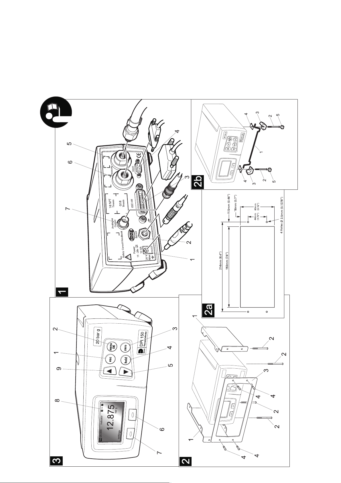
Druck DPI 150 User Manual
1 K344 Issue No. 2
Introduction
The Druck DPI 150 high accuracy, single-range pressure indicator uses the
Druck IDOS sensor to produce pressure readings in units of pressure
measurement and aeronautical units.
The instrument is contained in a moulded plastic case with integral rubber
feet for workbench surface use. Function keys, on the front panel, allow the
user to access an operating menu and set-up menu. Two more menus,
supervisor and calibration, allow the user to change the PIN codes,
communications settings and display language and for calibration of the
pressure sensor. A four digit PIN code protects both these facilities. The
electrical and pressure connections are located on the rear panel.
The instrument is supplied, as standard, with a RS232 data interface. Options
available include an IEEE 488 interface, an analogue output, a barometric
reference, negative calibration, external sensor and panel mount kit.
Specification
Conformity
Safety ...................................................................................... EN61010
EMC emission ......................................................................... EN61326
EMC immunity......................................................................... EN61326
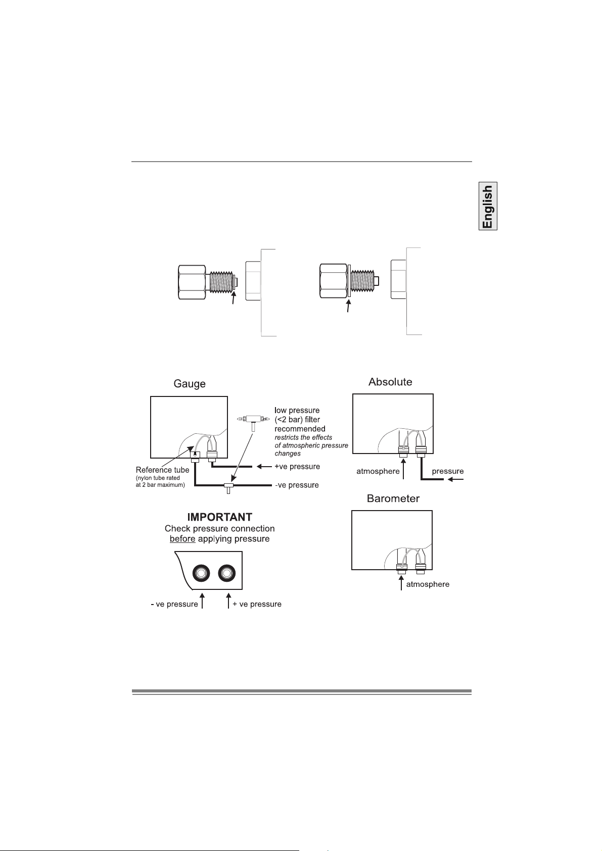
Gauge pressure ranges
....................................................................25, 70, 200, 350, 700 mbar
........................................1, 2, 3.5, 7, 10, 35, 70, 100, 135 and 200 bar
Absolute pressure ranges (using option E, barometric reference)
..................... add atmospheric pressure to the above gauge pressures
Maximum working pressure
0 to 350 mbar .................................................................. 2.0 x full-scale
0.7 to 2 bar, 3.5 to 70 bar, >100 bar ............................... 1.2 x full-scale
Precision
(includes non-linearity, hysteresis, repeatability and temperature effect between
18°C and 28°C [65° to 82°F]
below 1 bar....................................................................0.03% full-scale
1 bar to 200 bar.............................................................0.01% full-scale
Stability below 1 bar ............................................0.02% of reading/year
Stability above 1 bar............................................0.01% of reading/year
Option E, barometric reference
Pressure range .............................................. 750 to 1150 mbar absolute
Precision ................................................................................0.15 mbar
Accuracy
(includes non-linearity, hysteresis, repeatability and temperature effect
between 5°C and 50°C [41° to 120°F]
Stability...........................................................................0.15 mbar/year
Test Equipment Depot - 800.517.8431 - 99 Washington Street Melrose, MA 02176
FAX 781.665.0780 - TestEquipmentDepot.com