inbody 120 User manual

User’s Manual

©2018 InBody Co., Ltd. All rights reserved. BM-ENG-F3-E-180701
Please note the important information below before reading this manual.
Failure to comply with safety warnings and regulations can cause serious injury or death.
Failure to comply with safety cautions and regulations can cause injury or property damage.
DANGER
NOTECAUTION
참 조 주 의참 고 주 의
Warning
DANGER
NOTECAUTION
참 조 주 의참 고 주 의
Caution
Representative & Sponsor Information
EU Representative. [EUROPE]
DongBang Acuprime. 1 Forrest Units, Hennock Road East, Marsh Barton, Exeter EX2 8RU, U.K
Australian Sponsor. [AUSTRALIA]
Emergo AUSTRALIA. Level 20, Tower II, Darling Park, 201 Sussex Street, Sydney, NSW 2000, AUSTRALIA
TEL: +61-2-9006-1662 FAX: +61-2-9006-1010 Website: https://www.emergogroup.com E-mail: [email protected]
Customer Service Information
InBody [USA]
13850 Cerritos Corporate Dr., Unit C, Cerritos, CA 90703, USA
TEL: +1-323-932-6503 FAX: +1-323-952-5009 Website: https://www.inbody.com E-mail: contact@inbody.com
InBody Japan Inc. [JAPAN]
Tani Bldg., 1-28-6, Kameido, Koto-ku, Tokyo 136-0071 JAPAN
TEL: +81-3-5875-5780 FAX: +81-3-5875-5781 Website: https://www.inbody.co.jp E-mail: inbody@inbody.co.jp
InBody China. [CHINA]
904, Xing Di Plaza, No. 1698 Yishan Road, Shanghai, 201103, CHINA
TEL: +86-21-64439738, 9739, 9705
FAX: +86-21-64439706
Website: https://www.inbody.com
E-mail: [email protected]
InBody Co., Ltd. [HEAD OFFICE]
InBody Bldg., 54, Nonhyeon-ro 2-gil, Gangnam-gu, Seoul 06313 KOREA
TEL: +82-2-501-3939 FAX: +82-2-578-2716
Website: https://www.inbody.com
E-mail: info@inbody.com
©2018 InBody Co., Ltd. All rights reserved.
Reproduction, adaptation, or translation of this manual is prohibited without prior written consent from InBody Co., Ltd
under the copyright laws. This manual might have typographical errors, and its content can be changed without a prior
notice. InBody Co., Ltd shall not be liable for any errors, incidental, or consequential damages that occurred by not
complying with the content of the User’s Manual.
Visit our website https://www.inbody.com to view and download further information about the functions of the
InBody120, the explanation of results output, and more. InBody Co., Ltd reserves the right to modify the appearance,
specifications, and etc. of the InBody120 to improve the quality of the product, without prior notice for reasons of
performance improvement.

User’s Manual Contents
I. InBody120 Installation
A. Product Components
B. Operating Environment
C. Installation Instructions
D. Initial Setup
E. Connecting Lookin’Body120 (Data Management
Software) and Thermal Printer
F. Optional Installation Instructions
G. Maintenance
II. InBody Test
A. Precautionary Steps
B. Test Instructions
C. Test Posture
III.
Transportation and Storage
A. Repacking Instructions
B. Transportation and Storage Environment
I V.
Frequently Asked Questions (FAQ)
A. Regarding the InBody
B. Regarding the InBody Test
V. Others
A. Exterior and Functions
B. Safety Information
C.Classication
D.Specications
E. EMC declaration
4
6
6
10
12
17
20
21
22
24
25
25
26
28
29
31
33
33
35

4 5
I. InBody120 Installation
A. Product Components
The InBody120 consists of the following components. Make sure all of the following components are present.
*Please inspect each component of the InBody120 for defects prior to installation.
InBody120
Adapter (DC 12V, 3.4A) 1 EA
Power cord 1 EA
Battery (AA) 4 EA
User’s Manual 1 EA
Keypads
Control
handle
Footplate
Hand electrodes
Foot electrodes
120
User’s Manual
제품보증서
120
User’s Manual
제품보증서
120
User’s Manual
제품보증서
120
User’s Manual
제품보증서

4 5
*
Optional Equipments
1) InBody120 Stand
InBody120 Stand 1 EA
120
User’s Manual
제품보증서
2) Lookin’Body120 (Data Management Software)
Lookin’Body120 CD 1 EA
Lookin’Body Bluetooth Dongle (InBT-USB) 1 EA
3) Thermal Printer
Thermal Printer 1 EA
Thermal Printer Cable 1 EA
Thermal Printer Paper 1 EA
Thermal Printer Holder 1 EA
Thermal Printer Screws 4 EA
45mm 57mm
6 7
B. Operating Environment
Please make sure that the environment is adequate for the InBody120 installation. This equipment is designed
forindooruse.Ifinstallingoutdoors,thefollowingrequirementsmustbefullled.
C. Installation Instructions
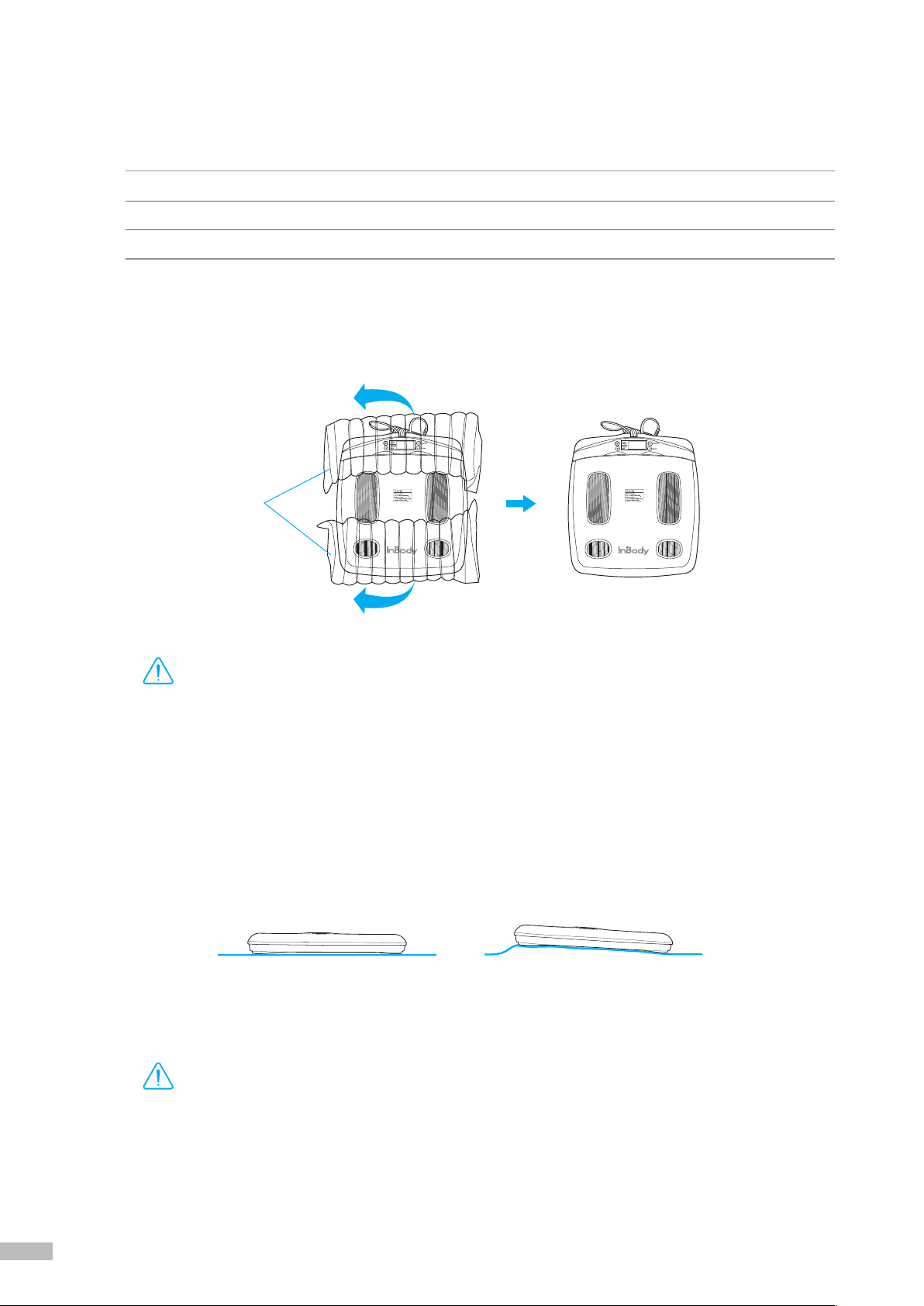
1.OpenthepackingboxoftheInBody120andremovetheinatableaircushion.
2.Afterremovingtheinatableaircushion,placetheInBody120onaleveledsurface.
* Leveling the equipment is necessary for accurate weight measurement.
Temperature range 10~40˚C (50~104˚F)
Relative humidity 30 ~ 75% RH
Atmospheric pressure 70 ~ 106kPa
Inatable air cushion
Leveled Not leveled
•
If you have any problems installing your InBody120, please contact InBody for assistance.
•
Keep the packaging materials provided for repacking the equipment in the future. Other wastes should be
disposed of according to relevant laws and regulations.
DANGER
NOTECAUTION
참 조 주 의참 고 주 의
Caution
•
Install the InBody120 on a leveled, non-vibrating surface. Installing the equipment on an uneven surface
may cause the examinee to fall down. Test results may also be inaccurate.
•
Never clean the hand and foot electrodes with liquid spray or detergent directly. The equipment may corrode
and/or malfunction if the liquid or detergent leaks inside. Use the InBody Tissue when cleaning the InBody120.
*
For inquires regarding the InBody Tissue, Please contact InBody.
DANGER
NOTECAUTION
참 조 주 의참 고 주 의
Caution

6 7
3. Separate the control handle and the footplate.
DANGER
NOTECAUTION
참 조 주 의참 고 주 의
Warning
•
Do not place the InBody120 in a location making it difficult to disconnect the power cord.
•
Do not plug in or pull out the power cord with wet hands. There is a risk of an electric shock.
•
Always use an outlet connected to the rated power (AC 100~240 V). Using other power rated outlets may
result in fire or malfunction.
•
When using a power surge protector, make sure the outlet or the extension cable has adequate power capacity.
•
Do not disassemble or modify the equipment, including internal parts, without written consent from the
manufacturer. This may cause electric shock or injury, product malfunction, inaccurate results, and will
void the manufacturer’s warranty.
•
Do not directly contact the InBody120 with any other electronic devices when the InBody120 is on.
This may result in an electric shock.
4. Connect the adapter ( ) to the power input port, which is located on the rear panel of the InBody120 ( ).
Connect the adapter ( ) to the power cord ( ). Then, plug the power cord ( ) into a grounded 3-socket outlet.
*The InBody120 can be used in connection with the data management software, Lookin’Body120. For more information, please refer
to ‘E. Connecting Lookin’Body120 (Data Management Software) and Thermal Printer 1. Lookin’Body120 (Data Management
Software)’ in this User’s Manual.
Power input port
Rear panel
Ground wire
3-socket outlet

8 9
5. Press the [On/Off] button to turn on the InBody120.
On/Off button
•If the InBody120 is not plugged into a grounded outlet, it may cause damage through electric surges or
product malfunction. This may affect the test results.
•Test results may be inaccurate if the InBody120 is under electrical interference. Do not install the InBody120
near products that generate electrical interference such as fluorescent lights, large AC motor equipment (treadmill,
vibration plate, refrigerator, air-conditioner, compressor, etc.), high-frequency thermal therapy equipments, or
heating appliances. Do not share the power source of the InBody120 with other electrical devices. This may
affect the test results.
•Always use the specified adapter provided by InBody, as it is a part of the InBody120. Using other adapters
may result in malfunction of the InBody120.
•Operation of the InBody120 2000m above sea level may affect the weight measurement.
DANGER
NOTECAUTION
참 조 주 의참 고 주 의
Caution

8 9
6. Follow the instructions below when using batteries.
* When using batteries, the InBody120 will automatically power off when it is not in use for 2 minutes and 30 seconds.
* The InBody120 will not automatically power off when connected with Lookin’Body120.
* Thermal Results Sheet will only print when the InBody120 is plugged into an outlet.
1) Open the battery socket lid which is located on the bottom of the InBody120.
2) Insert 4 AA batteries.
3) Cover the battery socket with the battery socket lid.
Battery socket lid
Bottom of the InBody120
10 11
D. Initial Setup
1. The InBody120 automatically starts booting when it is turned on. While booting, it performs a self weight
calibration.
*While booting (about 7 seconds), make sure there is nothing on top of the footplate. Please do not stand on the footplate, or place
objects on the footplate.
2. Press and hold the
[▲]
and
[▼]
buttons for 3 seconds to enter ‘Setup’, when no one is on the footplate.
3. The ‘Setup’ will give you access to setup the language and measuring units.
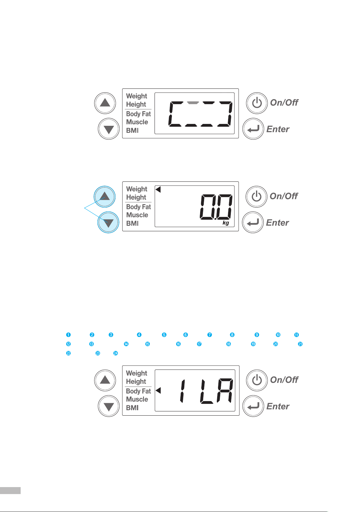
1) Language: Setup the language when the following LCD appears. The settings will be applied to the
Thermal Results Sheet.
a.Select‘1LA(1.LanguageConguration)’,usingthe[▲]or[▼]buttonandpressthe[Enter]button
tocongure.
b.Setthelanguageusingthe[▲]or[▼]button.
* The InBody120 offers 24 different languages. Please refer following language list and its number.
c. Save changes by pressing the [Enter] button.
Language conguration
[▲]
and
[▼]
buttons
English Arab Bulgarian Chinese Czech Finnish French German Greek Italy Japanese
Korean Netherlandic Polish Portuguese Brazil Romanian Russian Slovak Spanish Maxican
Taiwanese Thai Turkish

10 11
2) Units: Setup the measuring units when the following LCD appears. The settings will be applied to the
LCD result screen and the Thermal Results Sheet.
a.Select‘2Ut(2.MeasuringUnitConguration)’,usingthe[▲]or[▼]buttonandpressthe
[Enter]buttontocongure.
b. Set the measuring units using the [▲] or [▼] button.
Weight unit: kg, height unit: cm
Weight unit: lbs, height unit: ft. in.
c. Save changes by pressing the [Enter] button.
3)Afterconguringlanguageandmeasuringunits,select‘End’usingthe[▲]or[▼]buttonandpress
the [Enter] button to exit. The settings will be saved and the InBody120 is now ready for testing.
Unit conguration
12 13
E. Connecting Lookin’Body120 (Data Management Software) and Thermal Printer
1. Lookin’Body120 (Data Management Software)
PleasemakesurethefollowingrequirementsarefullledinordertoconnecttheInBody120toLookin’Body120.
•Make sure the Lookin’Body Bluetooth Dongle (InBT-USB) is plugged into the USB port of your PC.
•The distance between the computer and the InBody should be less than 10m. The greater the distance
between the equipment and the computer, the weaker the Bluetooth connection will be.
•Please make sure there is minimal to no interference, such as walls, between the computer and the InBody.
1) Press the
[
On/Off
]
button to turn on the InBody120.
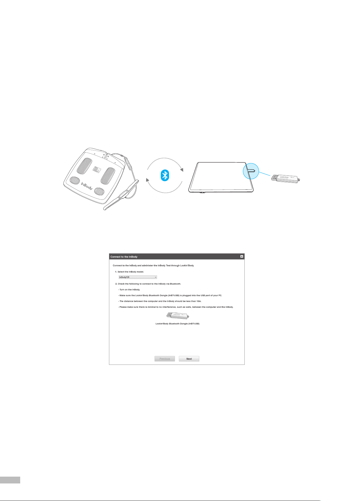
2) Please plug the Lookin’Body Bluetooth Dongle (InBT-USB) from the Lookin’Body120 box into the
USB port of your computer where Lookin’Body120 has been installed. Start Lookin’Body120.
3) Select ‘InBody120’ as the InBody model for Lookin’Body120 connection and click the [Next] button.
Lookin’Body Bluetooth Dongle
(InBT-USB)
12 13
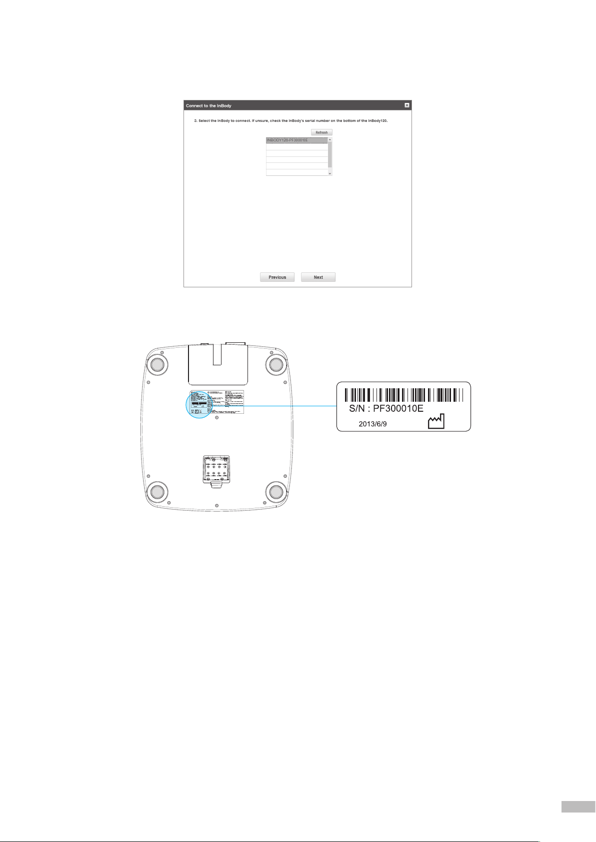
4) Lookin’Body120 willl start to search nearby InBody via Bluetooth. Select the appropriate InBody120
to connect.
*If having trouble selecting the appropriate InBody120, check your InBody’s serial number on the bottom of the InBody120.
Serial number
Bottom of the InBody120
14 15
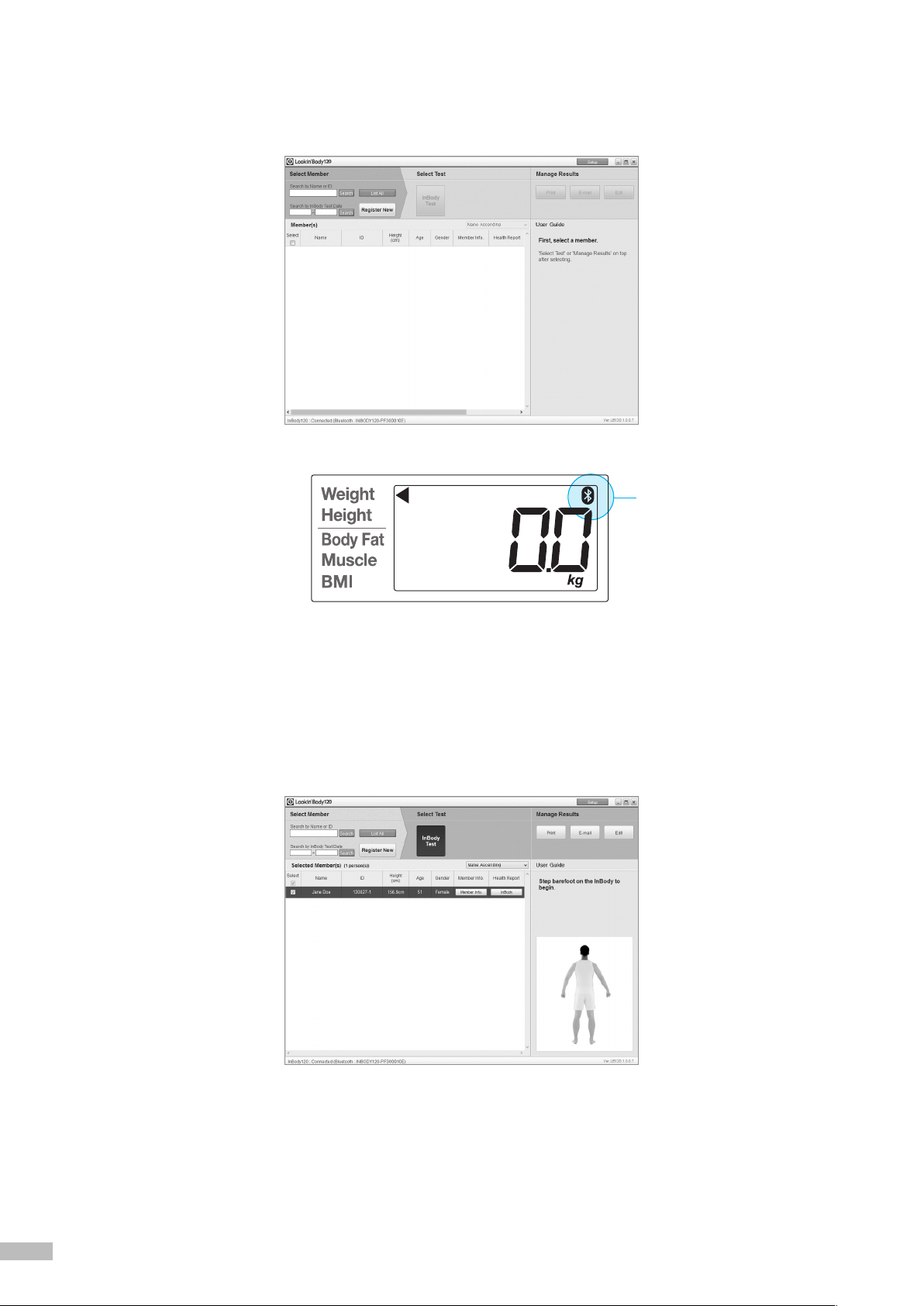
5) The following screen will appear on the computer when the InBody120 and Lookin’Body120 are connected
successfully. A corresponding Bluetooth icon will also appear on the LCD screen of the InBody120.
6) Click the [Register New] button to register new member and proceed to the InBody Test.
*For more information about Lookin’Body120, please refer to the Lookin’Body120 User’s Manual.
*Whether running on the adapter or battery power, the InBody120 will not automatically turn off when connected to Lookin’Body120.
Bluetooth icon

14 15
2. Thermal Printer
In order to print a Thermal Results Sheet, an InBody120 compatible Thermal Printer is required.
*Always connect a Thermal Printer from InBody.
1) Open the Thermal Printer lid. Insert a roll of the Thermal Printer Paper in the direction illustrated.
*Please refer to the following illustration to insert the paper in proper direction.
*Please refer to the Thermal Printer Paper size below.
•
External diameter: 45mm
•
Width: 57mm
•
Total length of the Thermal Printer Paper (unrolled): 23 ~ 24m
Correct (O) Incorrect (X)
45mm 57mm
45mm
57mm
Thermal Printer lid
Thermal Printer paper
16 17
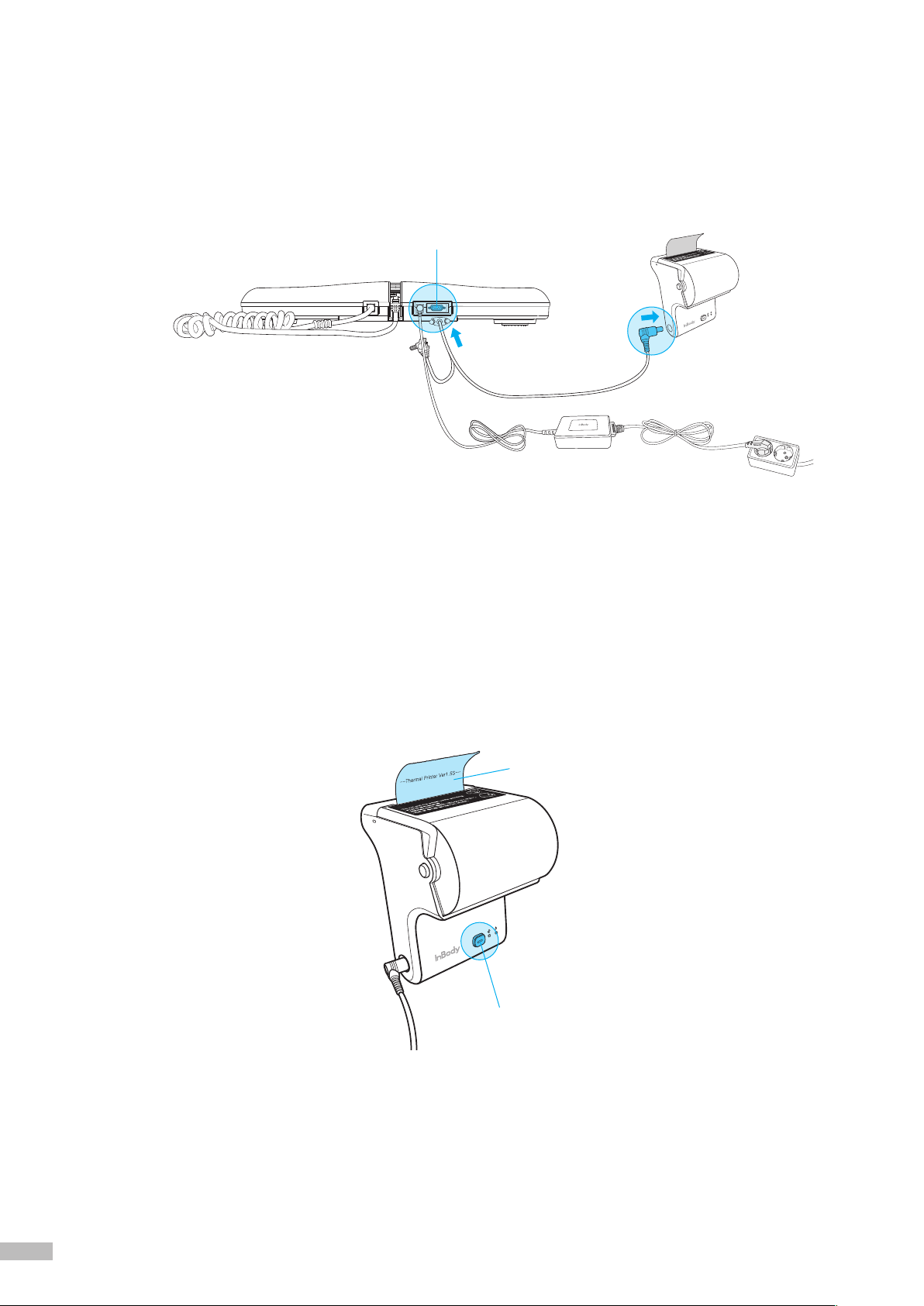
3) Turn on the InBody120.
4) Turn on a Thermal Printer. The Thermal Printer will print a sample results sheet when properly
connected.
*When properly connected, the Thermal Results Sheet will automatically print after each InBody Test. To re-print the
last test result, press and hold the [Enter] button for over 3 seconds.
*Pull down and tear off the Thermal Results Sheet using the sharp edges on the Thermal Printer.
2) Plug the serial cable provided with the Thermal Printer into the serial port on the rear panel of the
InBody120. Plug the other end of the serial port into the printer.
*Thermal Results Sheet will only print when the InBody120 is plugged into an outlet.
*Thermal Results Sheet will not print if the InBody120 is being powered by batteries.
Power button
Sample result
Serial port
16 17
F. Optional Installation Instructions
1. InBody120 Stand
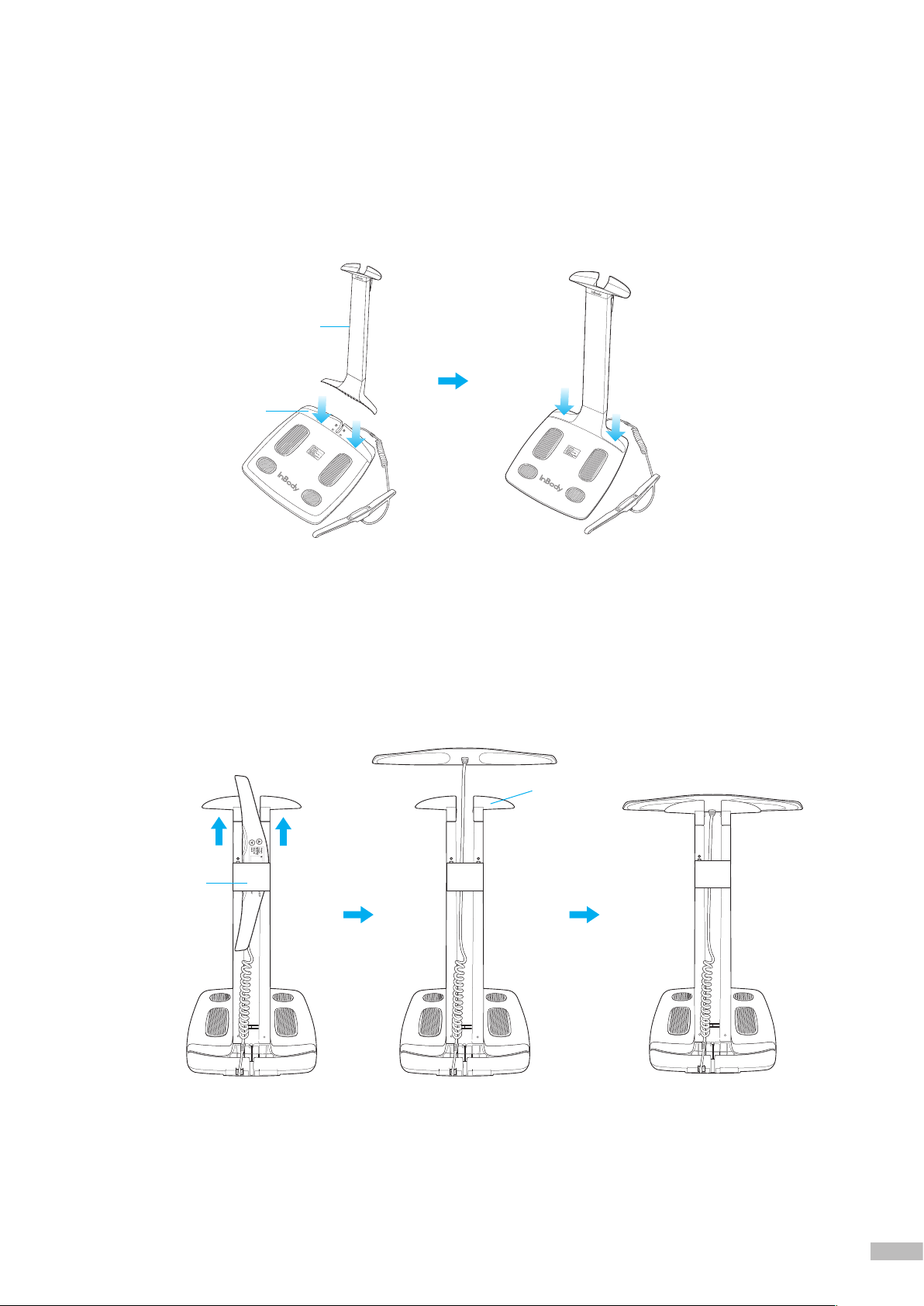
1) Separate the control handle from the footplate. Insert the InBody120 Stand into the designated spot as
shown in the illustration below.
2)AfterttingtheInBody120Standintothedesignatedspot,pressdownrmlytosecureitinplace.
3) Feed the control handle through the bottom of the cable protector, then place the handle on the
handle holder.
*The cable protector will prevent damages in cases where the control handle is dropped.
InBody120 Stand
Designated spot
Handle holder
Cable
protector

18 19
2. Thermal Printer
The Thermal Printer can be installed onto the InBody120 Stand.
1) Align the screw holes on the back of the Thermal Printer with the Thermal Printer Holder and insert the
screws from the Thermal Printer Holder to the Thermal Printer as illustrated below, then tighten.
2) Insert the Thermal Printer Holder Hook into the designated opening on the side of the cable protector
as illustrated below.
3) Align the screw hole below the hook on the Thermal Printer Holder with the corresponding hole on the
side of the cable protector.
Screw holes
Thermal Printer Holder
Thermal Printer
Holder
Cable
protector
Thermal
Printer Holder
Designated opening

18 19
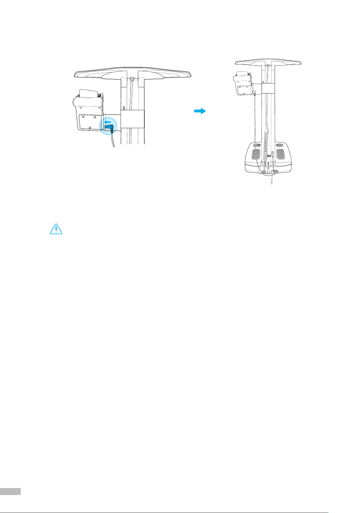
5) Plug the serial cable provided with the Thermal Printer into the serial port on the rear panel of the
InBody120. Plug the InBody120 Stand connector to back of the InBody120 Stand as illustrated below.
*The InBody120 Stand connector of the Thermal Printer cable will minimize the electrical shock through the Thermal Printer.
4) Tighten the screw from the Thermal Printer Holder to the cable protector as illustrated below.
To rear panel of the
InBody120
To the InBody120
Stand
To Thermal Printer
Thermal Printer cable
Serial port
Holder screw
20 21
6) Plug the Thermal Printer connecting part to the Thermal Printer.
G. Maintenance
•
Do not bend the handles of the hand electrode.
•
Do not place any objects on the footplate.
•
Do not apply excessive force on the equipment.
•
Turn off the equipment if you are not using it for a day or longer.
•
Do not allow any liquid substances contact to the equipment directly. Keep food and drinks away from the
equipment. Substances getting inside the equipment can cause critical damage to the electronic components.
•
Use a lint-free cloth to gently wipe the external surface of the equipment about once every week. Be careful not
to scratch the LCD screen.
•
When storing the InBody120, remove the batteries, repackage, and place the equipment on a leveled surface.
• InBody120 does not need regular maintenance. If some problems occur while operating the device, get in touch
with the store where you purchased it or A/S manager. We do not take the responsibility about problems caused
by any arbitrary repairs.
DANGER
NOTECAUTION
참 조 주 의참 고 주 의
Caution
Table of contents
Other inbody Personal Care Product manuals


