INDCO FL Series User manual

FL & FLG Series Mixers
tablEOFCONTENTS:
Safety & General ..........................................................2
Operation......................................................................3
Maintenance.................................................................3
Parts List ......................................................................4
4040 Earnings Way •New Albany, IN 47150
P: 812-941-5954 F: 812-944-9742
INDCO, Inc. • M-M-30115 mixer manual FL(G) Series • 5/13/05 • Page 1
FL & FLG
Flange
Mount
Series
Mixers
OWNERSMANUAL
Warranty
Our products are guaranteed against
defective materials and workmanship,
we will repair or replace such items
as may prove defective at our option.
Warranty period is one year on items
manufactured by INDCO, except for the
MixMaster Series Shakers which carries
a two year warranty. On items not
manufactured by INDCO, the
manufactures warranty applies. All
component parts of our products are
covered by this warranty, except for
normal wear items such as belts or
impellers. We cannot be responsible
for damage or abuse to equipment
caused by improper installation or
operation. Warranties can also be
voided by unauthorized disassembly of
equipment. For warranty repairs,
equipment is returned to INDCO at
the customer’s expense; we will repair
and return to customer at our expense.
Under no circumstances will we allow
labor charges or other expense to repair
defective merchandise. This warranty is
exclusive and is in lieu of all other
warranties, whether express or implied.
INDCO shall not be liable for any other
damages, whether consequential,
indirect, or incidental, arising from the
sale or use of its products.
INDCO, Inc. M-M-30115 mixer manual FL(G) date: 5/13/05
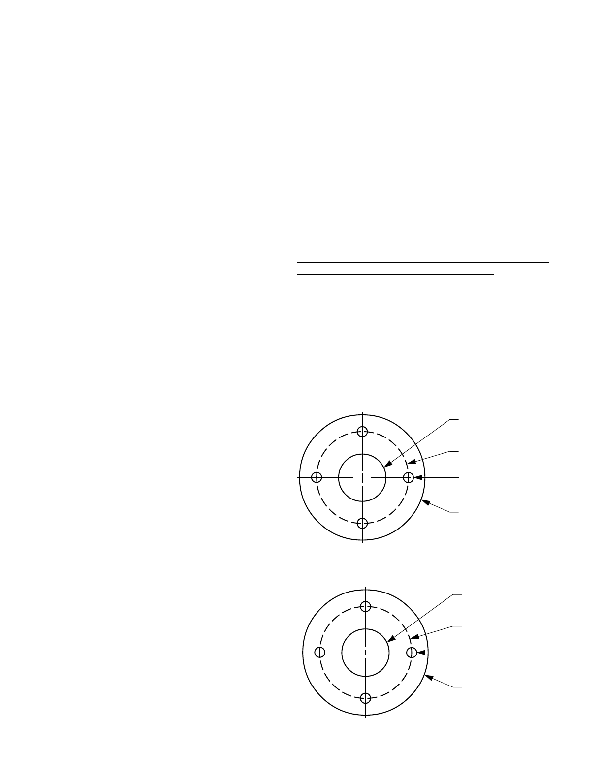
Mounting Flange - Air Motor with Hub Mount
Below is the mounting hole pattern for the flange, which is
cast aluminum.
1.5” FNPT
3.5” Bolt Circle
3/8” Holes, four
4-5/8” O.D.
1-1/8”
4-1/4” Bolt Circle
5/16” Holes, four
5-9/16” O.D.
Safety
Please follow the below safety precautions. If there are
any questions, please call INDCO at 800-942-4383.
Please read this complete manual before trying to operate
your mixer. Failure to follow these instructions could result
in serious bodily injury or death.
• Do not touch moving parts while mixer is operating.
Do not wear loose-fitting clothes or jewelry around an
operating mixer. Keep all hands, feet, clothes, neckties,
necklaces and other objects clear of moving parts.
• Never move the unit without a suitable lifting device.
• Have a qualified individual bring power to your unit.
• Always ground the unit. Never use an extension cord.
• Never run the unit in open air.
• Never adjust the speed without the unit running.
• Always lockout the power when working on the unit.
Electric Motor Safety:
Motors should be installed, protected and fused in
accordance with latest issue of National Electrical Code,
NEMA Standard Publication No. MG 2 and local codes.
Frames and accessories of motors should be grounded in
accordance with National Electrical Code (NEC) Article 430.
For general information on grounding refer to NEC Article
250.
Not all rotating parts are guarded. Keep hands and clothing
away from moving parts.
Trained, qualified personnel should make electrical repairs
and non-standard connections.
If environment has hazardous combustible fumes present,
use only explosion-proof electric motors.
Air Motor Safety:
The air motor is designed to be driven by compressed air
and under no circumstances be driven with any other gases.
Fluids, particles, solids or any substance mixed with air,
particularly combustible substances likely to cause
explosions, must not drive air motor.
• Do not drive with flammable or explosive gases or
operate unit in an atmosphere containing them.
• Air motor is designed for air only. Do not allow corrosive
gases or particulate material to enter motor. Water
vapor, oil-based contaminants, or other liquids must be
filtered out.
• Do not use a hammer or force coupling or drive pulley
onto shaft when installing drive onto air motor. This
causes end thrust that could damage air motor.
• Ambient temperature should not exceed 250°F.
• Beware of any exposed and/or movable parts. Proper
guards should be in place to prevent personal and/or
property damage.
• Solid or liquid material exiting unit can cause eye or
skin damage. Keep away from air stream.
• Always disconnect air supply before servicing.
• Do not allow air motor to “run free” at high speeds with
no loads. Excessive internal heat build-up, loss of
internal clearances and rapid motor damage will result.
• Some models may exceed 85dB(A) sound level.
Hearing protection should be worn when in close
proximity to these models.
General
• Single-phase TEFC models include cord, plug and switch.
• EP models must be wired in the field by the user.
• DC-Variable-Speed electric models have a controller
mounted to the mixer and they are pre-wired.
• Air motors include exhaust muffler.
FL(G) - Flange Mount Series
Flange mount mixers are ideal for agitation of un-sealed
vessels and can be fastened to almost any flat surface above
the tank.
Receiving
Before removing any packing, visually inspect the exterior of
the shipment for any sign of damage. Should there be any
damage, bring it to the attention of the delivering UPS or
truck line and note the same on the receiving ticket. Should
there be damage you must place a claim with the truck line.
They are the only ones who will pay for the damage done and
you are the only one who can place that claim.
Installation
Your new mixer requires some assembly. Ensure ALL set-
screws and fasteners on the unit have been tightened
completley before operating the equipment. The impeller(s)
and impeller-shaft have to be fitted to the machine before it’s
operational.
Mounting Flange - Air or Electric 56C Mount
Below is the mounting hole pattern for the flange, which is a
standard 150# floor flange - cast iron.
page 3 of 9

INDCO, Inc. M-M-30115 mixer manual FL(G) date: 5/13/05
Shaft & Coupler
To install mixer shaft, back off the set screws as far as
possible without removing them. Insert mixing shaft into
the coupler as far as it will go. Tighten ALL the set screws
firmly to secure the shaft to the coupler.
Impellers
The standard impellers are 3-bladed marine style. To install
the propeller, back off the set screw(s) as far as possible
without removing them. Insert mixing shaft into the bore
and tighten the set screw(s) firmly to secure the shaft to the
propeller.
shaft
set screws
Impeller Placement
For mixers with ONE impeller, mount it 1 to 2 impeller
diameters distance off the bottom of mixing container.
For mixers with TWO or more impellers, mount the lowest
impeller 1 to 2 impeller diameters distance off the bottom
of mixing container. Mount the other impellers 1 to 2 impeller
diameters apart. The uppermost impeller should be
positioned approximately 1 impeller diameter under the
surface of the liquid.
The above guide-lines are “rules of thumb” and may not be
the best for your situation. Experimenting with impeller
placement may provide your best results.
shaft coupler
set screws
shaft
Installation, continued
Gear Drive, FLG Series
• The gear box is filled with oil.
• The brass plug supplied loose is a Filler-Vent Plug.
After mounting the mixer, install the Filler-Vent Plug in
the highest filler point as shown below.
Filler-Vent Plug Location
• Remove Allen head plug
Drain Plug Location
page 4 of 9
Operation
Electric Power: Once the electric motor has been wired,
check rotation to be sure the mixer shaft is rotating in a
clock-wise direction, looking downward into the container.
Air Power: Check to ensure the air valve is in the closed
position, then connect air supply. Check rotation to be
sure the mixer shaft is rotating in a clock-wise direction,
looking downward into the container.
Once the mixer is in the container, it is now safe to
operate.
CAUTION:
9Never run mixer without a propeller.
9Never run the propeller in open air.
9Never run propeller outside a container.
Maintenance
Maintaining your mixer is not difficult if you follow these
guidelines:
- Keep the mixer clean.
- Check all set-screws and fasteners, tighten as needed.
- Check all wiring on a regular basis and repair as needed.
- Air motor powered units:
• Keep air supply dry and oil in the lubricator.
Lubrication:
Gear Drive Models:
The gear box contains oil from the factory.
The recommended replacement oil is:
- Gearbox models #RPQ1 and RPQ2:
• Mobil Extra Hecla
• Shell Oil Omala 680
• Texaco Meropa 680
• or equivalent to above
- For 50°F to 125°F ambient.
- RPQ1 Oil capacity is 11 ounces.
- RPQ2 Oil capacity is 14 ounces.

INDCO, Inc. M-M-30115 mixer manual FL(G) date: 5/13/05
MTR-3/4-HUB-AIR-CCW Hub Mount - 3/4 HP (2AM-NCC-16) CCW rotation only
N-K202 Repair Kit* (2AM-NCC-16)
MTR-3/4-56C-AIR 56C Mount - 3/4 HP (2AM-NRV-90) bi-rotational
N-K510 Repair Kit* (2AM-NRV-90)
HDW-1/4-VALVE Needle valve, brass - 1/4”
HDW-2502-SNB Pipe nipple, steel - 1/4” X 2”
N-AL445 Muffler, plastic
N-AC980 Muffler, metal
MTR-1.5-HUB-AIR Hub Mount - 1.5 HP (4AM-NRV-22B) bi-rotational
N-K205 Repair Kit* (4AM-NRV-22B)
MTR-1.5-56C-AIR 56C Mount - 1.5 HP (4AM-NRV-50C) bi-rotational
N-K206A Repair Kit* (4AM-NRV-50C)
HDW-1/4-VALVE Needle valve, brass - 1/4”
HDW-25-CNG Pipe nipple, steel - 1/4” X 7/8”
N-AL445 Muffler, plastic
N-AC980 Muffler, metal
MTR-4-56C-AIR 56C Mount - 4 HP (6AM-NRV-11A) bi-rotational
N-K208 Repair Kit* (6AM-NRV-11A)
HDW-1/2-VALVE Needle valve, brass - 1/2”
HDW-50-CNG Pipe nipple, steel - 1/2” X 1-1/8”
N-AC990 Muffler, metal
* Repair Kits include: Vanes, shaft seal, o-rings, DE & NDE bearings,
body & end cap gaskets.
Air Motors
Parts List - Drive Motors
3/4 HP1.5 HP4 HP
Item 100 Part No. Description
MTR-1/3-56C-1-EP 56C, fixed speed 1/3 HP Explosion-Proof 115/230VAC 1-phase
MTR-1/3-56C-1-TEFC 56C, fixed speed 1/3 HP TEFC 115/230VAC 1-phase
CPG-INLINE-18/3 Cord 18/3 - 6’, plug and in-line ON-OFF switch
MTR-098004 56C, variable speed 1/3 HP TEFC 115VAC to 90VDC 1-phase
MTR-DC-CONTROL DC motor controller, variable speed - 1/3 thru 2HP
CPG-18/3 Cord 18/3 - 6’ with plug
MET-VSO-BRACKET Angle brackets, mounts v.s. controller to motor (2 req’d)
1/3 HP
Electric Motors
page 6 of 9

INDCO, Inc. M-M-30115 mixer manual FL(G) date: 5/13/05
MTR-1/2-56C-1-EP 56C, fixed speed 1/2 HP Explosion-Proof 115/230VAC 1-phase
MTR-1/2-56C-1-TEFC 56C, fixed speed 1/2 HP TEFC 115/230VAC 1-phase
CPG-INLINE-18/3 Cord 18/3 - 6’, plug and in-line ON-OFF switch
MTR-098000 56C, variable speed 1/2 HP TEFC 115VAC to 90VDC 1-phase
MTR-DC-CONTROL DC motor controller, variable speed - 1/3 thru 2HP
CPG-18/3 Cord 18/3 - 6’ with plug
MET-VSO-BRACKET Angle brackets, mounts v.s. controller to motor (2 req’d)
MTR-3/4-56C-1-EP 56C, fixed speed 3/4 HP Explosion-Proof 115/230VAC 1-phase
MTR-3/4-56C-1-TEFC 56C, fixed speed 3/4 HP TEFC 115/230VAC 1-phase
CPG-14/3 Cord 14/3 - 5’ with plug
SWT-TOGGLE ON - OFF switch
SWT-GUARD Switch guard
MTR-108018 56C, variable speed 3/4 HP TEFC 115VAC to 90VDC 1-phase
MTR-DC-CONTROL DC motor controller, variable speed - 1/3 thru 2HP
CPG-14/3 Cord 14/3 - 5’ with plug
MET-VSO-BRACKET Angle brackets, mounts v.s. controller to motor (2 req’d)
MTR-1-56C-1-EP 56C, fixed speed 1 HP Explosion-Proof 115/230VAC 1-phase
MTR-1-56C-1-TEFC 56C, fixed speed 1 HP TEFC 115/230VAC 1-phase
CPG-14/3 Cord 14/3 - 5’ with plug
SWT-DP-TOGGLE ON - OFF switch
SWT-GUARD Switch guard
MTR-108022 56C, variable speed 1 HP TEFC 115VAC to 90VDC 1-phase
MTR-DC-CONTROL DC motor controller, variable speed - 1/3 thru 2HP
CPG-14/3 Cord 14/3 - 5’ with plug
MET-VSO-BRACKET Angle brackets, mounts v.s. controller to motor (2 req’d)
Electric Motors
Parts List - Drive Motors (continued)
1 HP 3/4 HP
Item 100 Part No. Description
1/2 HP
page 7 of 9

INDCO, Inc. M-M-30115 mixer manual FL(G) date: 5/13/05
Parts List: FL(G) Series
Air Motor
Hub Motor Mount
- Direct Drive -
Air & Electric Motor
56C Motor Flange
- Direct Drive -
Air & Electric Motor
56C Motor Flange
- Gear Drive -
300
400
201
100
200
501
502
100
500
201
300
400
300
400
201
100
100
501
502
page 8 of 9

INDCO, Inc. M-M-30115 mixer manual FL(G) date: 5/13/05
Item Description Part No. Qty.
100. Motor, air see ‘Parts List - Drive Motors’ 1
100. Motor, electric see ‘Parts List - Drive Motors’ 1
200. Gear Box, 5:1 ratio HDW-GB-56C 1
200. Gear Box, 5:1 ratio for: FLG-4A only HDW-GB-56C-LG 1
201. Coupling - shaft, 1/2” bore X 5/8” bore - stainless CPL-5062 1
201. Coupling - shaft, 5/8” bore X 5/8” bore - stainless CPL-6262 1
201. Coupling - shaft, 5/8” bore X 3/4” bore - stainless CPL-6275 1
300. Shaft - impeller, 5/8” dia. X 36” long - stainless SS636 1
300. Shaft - impeller, 3/4” dia. X 48” long - stainless N-SHF-7548 1
400. Impellers specify model 1~2
401. Set screw (not shown) specify model 2~4
Mounting Flange Assembly:
500. Hub Mount, air motors - cast aluminum N-MNT-FLA 1
501. 56C Face Mount, Air & Electric motors - cast aluminum w/ floor flange N-MNT-FLE 1
502. Floor Flange, 1.5”, 150# - cast iron HDW-150-FLANGE 1
Parts List: FL(G) Series
page 9 of 9
This manual suits for next models
1
Table of contents
Other INDCO Mixer manuals

INDCO
INDCO FGM 5 Gal Series User manual

INDCO
INDCO TL Series User manual

INDCO
INDCO MX3 Series User manual

INDCO
INDCO TMD Series User manual

INDCO
INDCO BT Series User manual

INDCO
INDCO TM Series User manual

INDCO
INDCO DL Series User manual

INDCO
INDCO CL Series User manual

INDCO
INDCO CB Series User manual

INDCO
INDCO BM Series User manual


