INDCO BT Series User manual

OWNERSMANUAL
BT and BGF Series Mixers
TABLEOFCONTENTS:
Safety & General ................................................................................2
Operation ..............................................................................................3
Maintenance ........................................................................................4
Troubleshooting .................................................................................5-9
Parts List................................................................................................. 10-11
4040 EARNINGS WAY NEW ALBANY, IN 47150 P: 8129415954
F: 8129449742 INDCO.COM INFOINDCO.COM
Warranty
Our products are guaranteed against
defective materials and workmanship, we
will repair or replace such items as may
prove defective at our option. Warranty
period is one year on items manufactured
by INDCO. On items not manufactured by
INDCO, the manufactures warranty applies.
All component parts of our products are
covered by this warranty, except for normal
wear items such as belts or impellers. We
cannot be responsible for damage or
abuse to equipment caused by improper
installation or operation. Warranties
can also be voided by unauthorized
disassembly of equipment. For warranty
repairs, equipment is returned to INDCO
at the customer’s expense; we will repair
and return to customer at our expense.
Under no circumstances will we allow
labor charges or other expense to repair
defective merchandise. This warranty
is exclusive and is in lieu of all other
warranties, whether express or implied.
INDCO shall not be liable for any other
damages, whether consequential, indirect,
or incidental, arising from the sale or use of
its products.
Bracket
Mount
Mixers

Safety:
Please follow the below safety precautions. If there are any questions, please call INDCO at 800-942-4383. Please read this com-
plete manual before trying to operate your mixer. Failure to follow these instructions could result in serious bodily injury or death.
and other ojects clear of moving parts.
ELECTRIC MOTOR SAFETY:
Motors should be installed, protected and fused in accordance with latest issue of National Electrical Code, NEMA Standard
Publication No. MG 2 and local codes. Frames and accessories of motors should be grounded in accordance with National
Electrical Code (NEC) Article 430. For general information on grounding refer to NEC Article 250. Not all rotating parts are
standard connections. If environment has hazardous combustible fumes present, use only explosion-proof electric motors.
AIR MOTOR SAFETY:
The air motor is designed to be driven by compressed air and under no circumstances be driven with any other gases. Fluids,
particles, solids or any substance mixed with air, particularly combustible substances likely to cause explosions, must not drive air
motor.
thrust that could damage air motor.
damage.
clearances and rapid motor damage will result.
General:
INDCO bracket mount mixers are excellent for agitation of light to medium viscosity materials. The standard mounting bracket
BT Series - DIRECT Drive
models run from 300 to 3000RPM.
BGF Series - GEAR Drive
run from 40 to 400RPM.

:
Before removing any packing, visually inspect the exterior of the shipment for any sign of damage. Should there be any
damage, bring it to the attention of the delivering UPS or truck line and note the same on the receiving ticket. Should there be
damage you must place a claim with the truck line. They are the only ones who will pay for the damage done and you are the
only one who can place that claim.
INSTALLATION:
Frame Bracket Assembly
range. Two hand-knobs tighten bracket assembly to side of container.
Impeller Shaft - BT Series
To install mixer shaft, back o the set screws as far as possible without removing them. Insert mixing shaft into the coupler as
Impeller Placement
For mixers with ONE impeller, mount it 1 to 2 impeller diameters distance o the bottom of mixing container.
For mixers with TWO or more impellers, mount the lowest impeller 1 to 2 impeller diameters distance o the bottom of mixing container.
situation. Experimenting with impeller placement may provide your best results.
motor~gearbox
mounting plate
frame bracket
(small)
- adjustable -
hand-knob
frame bracket
(large)
34” to 48”
container size
6”
8.5”
BT
Series
set screws
impeller shaft
coupler,
mounted to
motor shaft

Impellers - BT Series
The standard impellers are 3-bladed marine style. To install the propeller, back o the set screw(s) as far as possible without
Impellers - BGF Series
The standard impellers arefFolding type. To install follow same procedure as BT Series, above.
Impeller Shaft - BGF series
Tighten set-screws securely.
shaft
set screw
shaft
set screw
(both sides)

INSTALLATION, CONTINUED:
Impeller Shaft - BGF series
Tighten set-screws securely.
OPERATION:
Electric Power:
Once the electric motor has been wired, check rotation to be sure the mixer shaft is rotating in a clock-wise direction, looking
downward into the container.
Air Power:
Check to ensure the air valve is in the closed position, then connect air supply. Check rotation to be sure the mixer shaft is
rotating in a clock-wise direction, looking downward into the container.
Once the mixer is in the container, it is now safe to operate. Always start and stop mixer in slowest speed.
CAUTION:
ü Never run mixer without a propeller.
ü Never run propeller outside a container.
gear box
impeller shaft
impeller
motor
set-screws
2 @ 90° apart
Rotation:
clock-wise looking
downward into
tank
Apply “anti-seize”
material in the
shaft ~ hollow quill
area.

MAINTENANCE:
Maintaining your mixer is not dicult if you follow these guidelines:
- Check all set-screws and fasteners, tighten as needed.
- Check all wiring on a regular basis and repair as needed.
- Air motor powered units:
Lubrication
BGF Series Models with Gear Reducers
- Winsmith 917 & 920 Series
Factory Filled:
the oil plug provided and while the unit is oriented in its operating position.
correct grade based on actual ambient temperatures.
Oil Changing:
When changing oil for any reason, it should be remembered that oils of various types may not be compatible. Therefore, when
if necessary.
Initial Oil Change:
The oil in a new speed reducer should be changed at the end of 250 hour of operation.
Subsequent Oil Changes:
Under normal conditions, after the initial oil change, the oil should be changed after every 2,500 hours of operation, or every six
may be necessary to change oil at intervals of one to three months. Periodic examination of oil samples taken from the unit will
help establish the appropriate interval.
Synthetic Oils:
Synthetic lubricants can be advantageous over mineral oils in that they generally are more stable, have longer life, and operate
over a wider temperature range. These oils are appropriate for any application but are especially useful when units are subjected
to remove metal particles that accumulate during break-in. Subsequent oil changes should be made after 5000 hours operation if
units are operating in a clean environment.
Oil Temperature:
the application (loading, duration of service, ambient temp.). Excessive temperature can result from overloading due to original

Lubricants:
Below is just a few of the recommended lubricants that should be used in your speed reducer.
Part No. Description
N-AC980 Muer, metal
N-AC980 Muer, metal
N-AC990 Muer, metal
phase
Ambient Temp. 16 to 50°F 51 to 110°F 111 to 165°F
Max.Op.Temp. 185°F 200°F 200°F
ISO Visc.Grade 460 680 1000
AGMA Lub.No. #7 Comp. #8 Comp. #8A Comp.
Mobil Oil 600W 600W Super Extra Hecla
Shell Oil Omala 460 Omala 680 Omala 800
Sun Oil Sunep 1110 Sunep 1150 Oil 8 AC
3/4 HP
Air Motors
Electric Motors
1/2 HP 4 HP 1.5 HP

Part No. Description
phase
SWT-TOGGLE ON - OFF switch
SWT-GUARD Switch guard
phase
phase
SWT-DP-TOGGLE ON - OFF switch
SWT-GUARD Switch guard
phase
phase
SWT-DP-TOGGLE ON - OFF switch
SWT-GUARD Switch guard
phase
1 HP
Electric Motors
1.5 HP 3/4HP

Parts List - BT Series Mixer:
502
505
504
503
506
501
509
508
300
400
210
101 102
100

Parts List - BT Series Mixer:
ITEM DESCRIPTION PART NO. QTY.
100. Motor, air see ‘Parts List - Drive Motors’ 1
100. Motor, electric see ‘Parts List - Drive Motors’ 1
400. Impellers specify model 1~2
401. Set screw (not shown) specify model 2~4
500. Bracket Ass’y Complete, consisting of: BT-403 1

Parts List - BGF Series Mixer:
100
102101
204
200
202201
509
203
300
400
401
502
505
504
503
506
508
501
204

Parts List - BGF Series Mixer:
ITEM DESCRIPTION PART NO. QTY.
100. Motor, air see ‘Parts List - Drive Motors’ 1
100. Motor, electric see ‘Parts List - Drive Motors’ 1
500. Bracket Ass’y Complete, consisting of: BT-403 1

Bracket Mount - Toggle Clamp Adjustment
3. Clamp should be located so that the handle is vertical.
4. Use bolts to secure clamp (FIG B).
Fig A
FIG. A
FIG. B1 FIG. B1

Bracket Mount - Toggle Clamp Adjustment, Continued
clamping on cage with toggle handle in vertical position.
7. Release clamp and install remaining hardware.
1/8”
FIG. C

Bracket Mount - Toggle Clamp Adjustment, Continued
bracket mount has not yet been fastened and should look similar to the picture in FIG- D.
9. Secure the two halves together with the included hardware as shown. Note that the hardware should be located
utilizing the slotted portion of the bracket.
FIG. D

Bracket Mount - Toggle Clamp Adjustment, Continued
between the J hook and the tote wire frame as shown in order to secure properly
11. Cage style as shown below please follow the instructions for latch adjustment.
Tighten nut until desired
tension is obtained.
1/8”
After clamp tension
is obtained secure J-
Hook from rotation by
tightening lower nut.

Bracket Mount - Toggle Clamp Adjustment, Continued
13. Adjust bracket to set of mounting holes as shown.
Tighten nut until desired
tension is obtained.
1/8”
After clamp tension
is obtained secure J-
Hook from rotation by
tightening lower nut.

Bracket Mount - Toggle Clamp Adjustment, Continued
14. After frame and bracket have been located the J hook then needs to be adjusted.
15. Rotate latch in the up position as shown.
At the same time loosen the top nylock nut so
Tighten nut until desired
tension is obtained.
1/8”
After clamp tension
is obtained secure J-
Hook from rotation by
tightening lower nut.
TOTE RAIL

Bracket Mount - Toggle Clamp Adjustment, Continued
tension. Adjust the tension as desired to secure the latch to the tote frame.
1/8”
After clamp tension
is obtained secure J-
Hook from rotation by
tightening lower nut.
This manual suits for next models
1
Other INDCO Mixer manuals
INDCO
INDCO BM Series User manual
INDCO
INDCO TL Series User manual
INDCO
INDCO FGM 5 Gal Series User manual
INDCO
INDCO DL Series User manual
INDCO
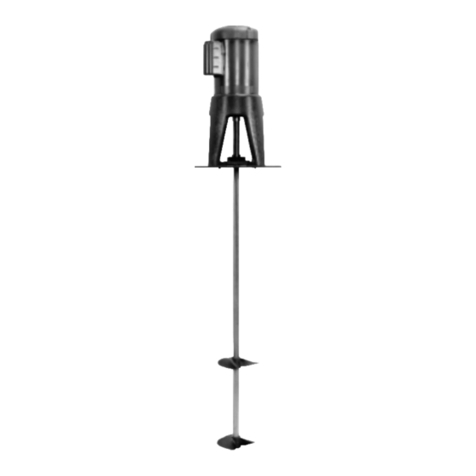
INDCO TM Series User manual
INDCO
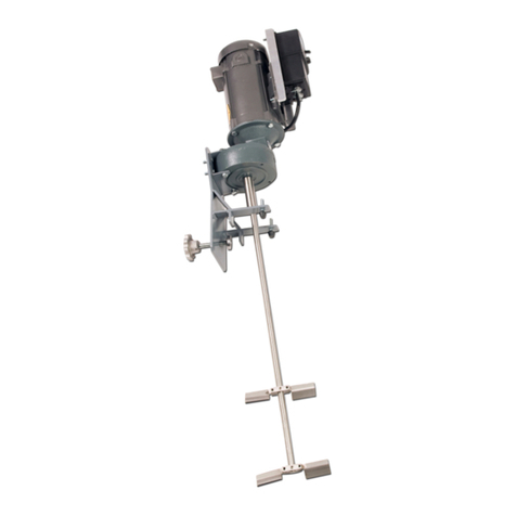
INDCO TMD Series User manual
INDCO
INDCO CB Series User manual

INDCO
INDCO CL Series User manual
INDCO
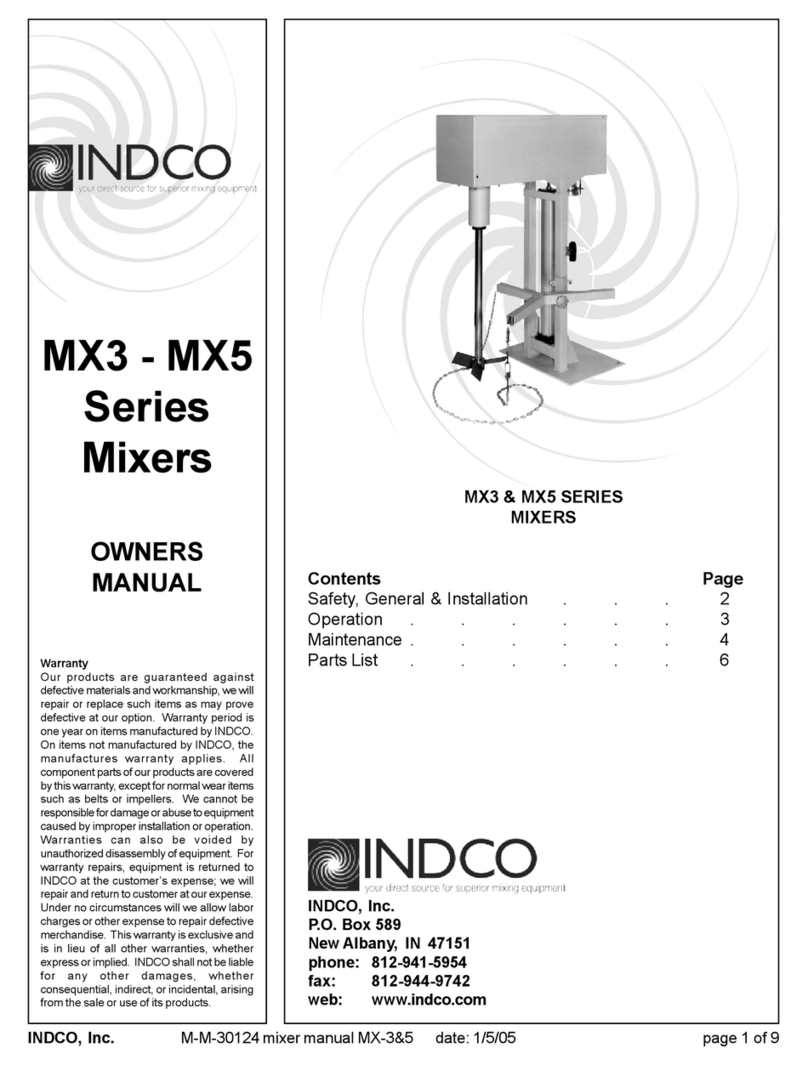
INDCO MX3 Series User manual

INDCO
INDCO FL Series User manual


