INDCO TM Series User manual

INDCO, Inc. M-M-30127 mixer manual TM(G) date: 1/5/05
TM(G) SERIES
TOP ENTRY MIXERS
Contents Page
Model Data ......2
Safety & General Info ....3
Installation ......4
Maintenance ......6
TM & TMG
Series
Mixers
OWNERS
MANUAL
INDCO, Inc.
P.O. Box 589
New Albany, IN 47151
phone: 812-941-5954
fax: 812-944-9742
web: www.indco.com
Warranty
Our products are guaranteed against
defective materials and workmanship, we will
repair or replace such items as may prove
defective at our option. Warranty period is
one year on items manufactured by INDCO.
On items not manufactured by INDCO, the
manufactures warranty applies. All
component parts of our products are covered
by this warranty, except for normal wear items
such as belts or impellers. We cannot be
responsible for damage or abuse to equipment
caused by improper installation or operation.
Warranties can also be voided by
unauthorized disassembly of equipment. For
warranty repairs, equipment is returned to
INDCO at the customer’s expense; we will
repair and return to customer at our expense.
Under no circumstances will we allow labor
charges or other expense to repair defective
merchandise. This warranty is exclusive and
is in lieu of all other warranties, whether
express or implied. INDCO shall not be liable
for any other damages, whether
consequential, indirect, or incidental, arising
from the sale or use of its products.
page 1 of 8

INDCO, Inc. M-M-30127 mixer manual TM(G) date: 1/5/05
TM & TMG Series Top Entry Mount Mixers
- SPECIFICATION SHEET -
100 - Motor:
Part no.:
HP: RPM:
volts: cycles: phase:
frame: enclosure:
200 - Gear Reducer:
Part no.:
Model No.:
Ratio:
RPM output:
300 - Shaft:
Diameter
402 - Impeller, upper:
Diameter
Type
401 - Impeller, center:
Diameter
Type
mounting flange
see page 4.
Model:
Serial No.:
Date:
Order No.:
Rotation:
clock-wise looking
downward into tank
99”
page 2 of 8
402 - Impeller, lower:
Diameter
Type

INDCO, Inc. M-M-30127 mixer manual TM(G) date: 1/5/05
General
INDCO’s TM series - top mounted heavy duty gear drive
mixers are designed for handling large volumes and are
the most common and most efficient mixer used in the
process industry.
INDCO’s TMG series - top mounted heavy duty gear drive
mixers are designed for handling low viscosity materials in
large batches or small batches of heavy material that are
beyond the range of direct drive mixers.
Both the above mixers feature axial flow impellers that
generate downward flow for optimum circulation and mixing.
Operation
Electric Power: Once the electric motor has been wired,
check rotation to be sure the mixer shaft is rotating in a
clock-wise direction, looking downward into the container.
Air Power: Check to ensure the air valve is in the closed
position, then connect air supply. Check rotation to be
sure the mixer shaft is rotating in a clock-wise direction,
looking downward into the container.
Once the mixer is in the container, it is now safe to
operate. Always start and stop mixer in slowest speed.
CAUTION:
9Never run mixer without an impeller.
9Never run the impeller in open air.
Safety
Please read this complete manual before trying to install or
operate your mixer.
• High voltage and rotating equipment can cause serious
or fatal injury.
• Never move the unit without a suitable lifting device
and do not lift mixer by shaft.
• Have a qualified individual operate and service this
equipment.
• Never run the unit in open air.
• Always lockout the power when working on the unit.
Electric Motor Safety:
Motors should be installed, protected and fused in
accordance with latest issue of National Electrical Code,
NEMA Standard Publication No. MG 2 and local codes.
Frames and accessories of motors should be grounded in
accordance with National Electrical Code (NEC) Article 430.
For general information on grounding refer to NEC Article
250.
Not all rotating parts are guarded. Keep hands and clothing
away from moving parts.
Trained, qualified personnel should make electrical repairs
and non-standard connections.
If environment has hazardous combustible fumes present,
use only explosion-proof electric motors.
Air Motor Safety:
The air motor is designed to be driven by compressed air
and under no circumstances be driven with any other gases.
Fluids, particles, solids or any substance mixed with air,
particularly combustible substances likely to cause
explosions, must not drive air motor.
• Do not drive with flammable or explosive gases or
operate unit in an atmosphere containing them.
• Air motor is designed for air only. Do not allow corrosive
gases or particulate material to enter motor. Water
vapor, oil-based contaminants, or other liquids must be
filtered out.
• Do not use a hammer or force coupling or drive pulley
onto shaft when installing drive onto air motor. This
causes end thrust that could damage air motor.
• Ambient temperature should not exceed 250°F.
• Beware of any exposed and/or movable parts. Proper
guards should be in place to prevent personal and/or
property damage.
• Solid or liquid material exiting unit can cause eye or
skin damage. Keep away from air stream.
• Always disconnect air supply before servicing.
• Do not allow air motor to “run free” at high speeds with
no loads. Excessive internal heat build-up, loss of
internal clearances and rapid motor damage will result.
• Some models may exceed 85dB(A) sound level.
Hearing protection should be worn when in close
proximity to these models.
Receiving
Before removing any packing, visually inspect the exterior of
the shipment for any sign of damage. Should there be any
damage, bring it to the attention of the delivering UPS or
truck line and note the same on the receiving ticket. Should
there be damage you must place a claim with the truck line.
They are the only ones who will pay for the damage done and
you are the only one who can place that claim.
page 3 of 8

INDCO, Inc. M-M-30127 mixer manual TM(G) date: 1/5/05
Installation
Motor to Gear Reducer Mounting Procedures
Motor to C-Flange:
• Check motor and reducer mounting registers for nicks
that would interfere with assembly. Remove if necessary.
• Remove protective plastic plug from reducer input shaft.
The bore has been coated with an anti-seize compound.
• Align the motor shaft and key with keyway in bore and
slide up to flange.
• Position the motor conduit box as desired.
• Using the fasteners supplied, secure the motor to the
reducer. Draw down evenly so as not to bend the motor
shaft. Tighten fasteners to 200 inch pounds.
Motor to C-Flange with Coupling:
• Check motor and reducer mounting registers for nicks
that would interfere with assembly. Remove if necessary.
• When assembling the motor and coupling, the coupling
halves should be equally spaced on each shaft to insure
adequate engagement. The following describes a method
for doing this.
First determine the assembled shaft clearance by measuring
the distance from the C-Flange face to the reducer shaft
end and subtracting the motor shaft length. Mount and
secure the motor shaft coupling half with the spider end
extending one half the clearance distance beyond the motor
shaft. Mount the reducer coupling half and coupling spider
on reducer shaft in its approximate position but do not
secure.
Locate the motor conduit box in the desired position and
secure the motor to the reducer flange using the fasteners
provided. Tighten to about 200 inch pounds.
Using the access hole in the flange, slide the coupling
together and tighten the set screw.
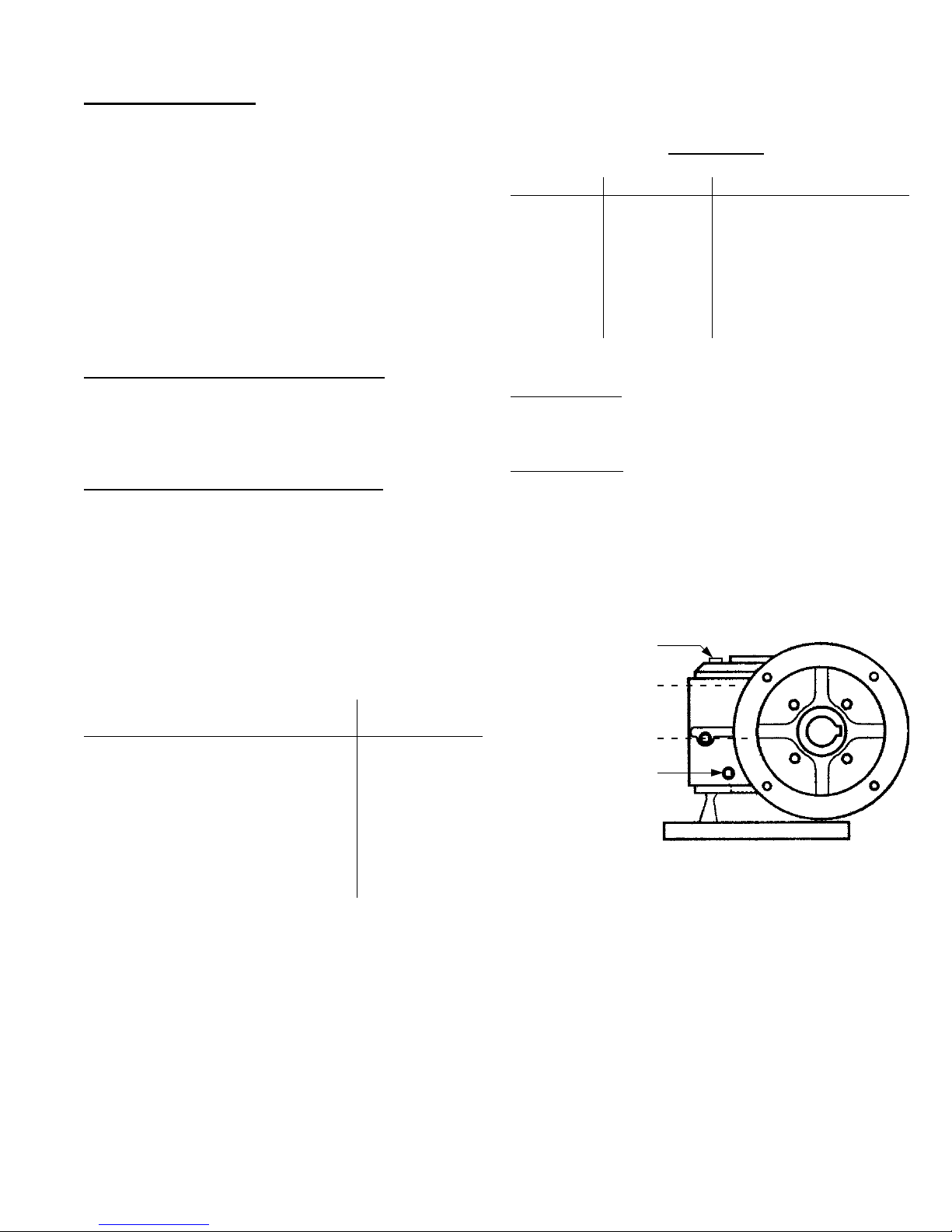
Mounting Flange Details
- Gear Reducer
Mixer Mounting Surface
The following tables and flange details
correspond with the Gear Reducer
model number for your mixer listed
on the Specification Sheet, page 2.
Gear reducers are listed by
manufacture and model series
number.
IPTS
50 100
0.41 0.41
7.0 9.0
model 21 26 30 35 400 500 600 H600
A 0.44 0.50 0.56 0.56 0.69 0.81 0.81 0.81
B 6.88 7.38 9.12 10.75 11.5 12.75 15.25 15.25
Electra-Gear
model 917 920 924 926 930 935 943
A 0.344 0.406 0.406 0.406 0.563 0.563 0.688
B 5.88 6.5 7.5 8 9.25 10 11.5
Winsmith
DIMENSIONS (in inches)
MOUNTING FLANGE DETAILS
B
bolt circle
A
4-holes
equally spaced
B
bolt circle
A
4-holes
equally spaced
page 4 of 8

INDCO, Inc. M-M-30127 mixer manual TM(G) date: 1/5/05
Installation, continued
Impeller Placement
Mixers with ONE impeller, mount it 1 to 2 impeller diameters
distance off the bottom of mixing container.
Mixers with TWO or more impellers, mount the lowest
impeller 1 to 2 impeller diameters distance off the bottom
of mixing container. Mount the other impellers 1 to 2 impeller
diameters apart. The uppermost impeller should be
positioned approximately 1 impeller diameter under the
surface of the liquid.
The above guide-lines are “rules of thumb” and may not be
the best for your situation. Experimenting with impeller
placement may provide your best results.
Impellers
If your unit has impellers with bolt-on blades, it will be up to
the installer wheather the blades are mounted to the hub
(tabs) before mounting hub to the shaft. Your application
may require the blades to be mounted to hub inside the
tank, after hub is mounted to shaft.
Impeller Shaft
The impeller shaft mounts through the hollow gearbox shaft.
Apply an “anti-sieze” material in the hollow gearbox quill
area. Align key with keyways in gearbox and impeller shaft.
Downward load is supported by a bolt and washer plate
that thread into the end of impeller shaft. Tighten securely.
bolt
gear reducer
impeller shaft
key
impeller
motor
flat washer plate
set-screws
2 @ 90° apart
Rotation:
clock-wise looking
downward into
tank
shaft
impeller
set-screw
To install the impeller, back off the set screws as far as
possible without removing them. Insert mixing shaft into
the bore and tighten the set screws firmly to secure the
impeller to the shaft. If your unit is supplied with a shaft
key, align and install. Most keyways should align with one
set-screw.
hub ~ tab
blade
bolts
set-screw
& keyway
Turbine with
Bolt-On blades
(top view)
Apply “anti-sieze”
material in the
shaft ~ hollow quill
area.
page 5 of 8

INDCO, Inc. M-M-30127 mixer manual TM(G) date: 1/5/05
Factory Filled:
Your new speed reducer is filled to the proper level for
standard mounting position with the appropriate grade of
oil for operation in a 51°F to 110°F temperature
environment. The oil level should be checked and adjusted
(if necessary) prior to operation, using the oil plug provided
and while the unit is oriented in its operating position.
If operating ambient temperature is outside the range
specified above, then refer to the lubrication chart and refill
the unit with the correct grade based on actual ambient
temperatures.
Oil Changing:
When changing oil for any reason, it should be remembered
that oils of various types may not be compatible. Therefore,
when changing to a different oil, it is recommended that
the housing be completely drained and thoroughly flushed
with a light flushing oil prior to refilling with the appropriate
lubricant. The oil level should be rechecked after a short
period of operation and adjusted if necessary.
Initial Oil Change:
The oil in a new speed reducer should be changed at the
end of 250 hour of operation.
Subsequent Oil Changes:
Under normal conditions, after the initial oil change, the oil
should be changed after every 2,500 hours of operation, or
every six months, whichever occurs first. Under severe
conditions (rapid temperature changes, moist, dirty or
corrosive environment) it may be necessary to change oil
at intervals of one to three months. Periodic examination
of oil samples taken from the unit will help establish the
appropriate interval.
Synthetic Oils:
Synthetic lubricants can be advantageous over mineral oils
in that they generally are more stable, have longer life, and
operate over a wider temperature range. These oils are
appropriate for any application but are especially useful
when units are subjected to low start-up temperatures or
high operating temperatures. However, continuous
operation above 225°F may cause damage to the seals or
other components. It is recommended that the initial oil be
changed or filtered after the first 1500 hours of operation to
remove metal particles that accumulate during break-in.
Subsequent oil changes should be made after 5000 hours
operation if units are operating in a clean environment.
Oil Temperature:
Speed reducers in normal operation can generate
temperature up to 200°F depending on the type of reducer
and the severity of the application (loading, duration of
service, ambient temp.). Excessive temperature can result
from overloading due to original unit selection being too
small for the application or increased load after original load
size was selected. Overfilling and Under filling the oil level
of a speed reducer will cause overheating. Ensure oil is at
the proper level.
Lubricants:
Below is just a few of the recommended lubricants that
should be used in your speed reducer.
Ambient Temp. 16 to 50°F 51 to 110°F 111 to 165°F
Max.Op.Temp. 185°F 200°F 200°F
ISO Visc.Grade 460 680 1000
AGMA Lub.No. #7 Comp. #8 Comp. #8A Comp.
Mobil Oil 600W 600W Super Extra Hecla
Shell Oil Omala 460 Omala 680 Omala 800
Sun Oil Sunep 1110 Sunep 1150 Oil 8 AC
Maintenance - Gear Reducer
Winsmith - 900 Series
filler ~ vent
plug
level
plug drain
plug
Gear Reducer
page 6 of 8
INDCO, Inc. M-M-30127 mixer manual TM(G) date: 1/5/05
Continuous Duty is defined as running more than 30 minutes
in an hour. If the unit is going to be run on a continuous
basis (more than half the time), it should be filled to the
continuous duty (low) level.
Intermittent Duty is defined as running less than 30 minutes
in an hour, or with an input speed of 800rpm or less.
However, use of the optional SEGL High Performance Oil
requires the continuous oil level be used in all cases,
regardless of running time or RPM.
Maintenance - Gear Reducer (continued)
Electra-Gear Series
Run In Period:
The maximum efficiency of the gear reducer is obtained
after a “run-in” period. The length of time required will
depend on the load applied and will be 8 to 12 hours at
rated load, and considerably longer at light loads.
During “run-in”, higher than normal motor currents, lower
efficiency, and lower output torque can be expected.
Overloading will not decrease “run-in” time, but may cause
severe wear.
Oil Change Time Table:
Standard Mobil 600W Lubricant (factory fill)
Drain and refill oil after first 100 hours of operation. Under
normal conditions, change oil every 2000 hours of operation
or 6 months, whichever occurs first. Check ambient
temperature limits of your oil to ensure it matches ambient
conditions.
SEGL Lubricant (special high performance)
Under normal conditions, change oil every 8000 hours of
operation or every three years, whichever occurs first.
Lubrication:
The speed reduce is filled to the proper level with lubricant,
Mobil 600W lube is the factory standard with SEGL being
the preferred option.
Recommended Lubricants:
Manufacture - Name Ambient Temp.
Range, deg.F
• Standard Factory Fill Lubricant:
Mobil - Mobil Cylinder 600W +32 to +100
• Special High Performance Lubricants:
Chem Age Ind. - SEGL Gear Lube -50 to +425
Mobil - Mobil SHC 634 0 to +100
Mobil - Mobil SHC 629 -25 to +100
Mobil - Mobil SHC 626 -40 to +40
The SEGL lubricants are available from:
New Age Chemical
3765 Kettle Court E.
Delafield, WI 53018
Oil Fill Capacities in
U.S. Pints
Frame Size Cont. Duty Int. Duty
21 1.1 2.0
26 1.8 3.4
30 2.8 5.0
35 3.5 7.0
400 4.0 9.25
500 8.0 17.0
600 11.0 26.5
filler ~ breather
intermittent oil level
continuous oil level
drain
Gear Reducer
page 7 of 8

INDCO, Inc. M-M-30127 mixer manual TM(G) date: 1/5/05
Factory Filled:
Reducers are shipped filled with oil. Before operating, the
breather plug must be installed in the top of the reducer.
When the reducer is mounted so that the output shaft is
vertical, the breather should be placed in the uppermost
side.
Oil Changing:
The oil in a new unit should be drained at the end of two
weeks operation or 100 hours, whichever comes first, and
the case thoroughly flushed with a light flushing oil. The
original oil can be used for refilling if it has been filtered;
otherwise new oil must be used. After this, a change of oil
every 2500 hours of operation or every six months,
whichever comes first, is recommended for units operating
under normal conditions. If the unit is operating in extremely
dirty or high temperature environments the oil should be
changed more often.
The unit should be filled when not running to the center of
the oil sight gauge or the oil level plug with Mobil 600W
cylinder oil or equivalent AGMA 7 or 7EP lubricant when
the ambient temperature does not exceed 90°F. For units
operating in ambient temperatures normally between 80°F
to 125°F, Mobil 600W super cylinder oil or equivalent AGMA
8 or 8EP lubricant is recommended.
Maintenance - Gear Reducer (continued)
IPTS - ICSF Series
Preventive Maintenance:
Shafts and vent plugs should be kept clean to prevent
foreign particles from entering seals or gear case. Inspect
periodically for proper oil level and replenish when
necessary.
Oil Fill Capacities in
Fluid Ounces
Frame Size, Vertical Output Cont. Duty
34 4
40 6
45 12
50 10
60 14
70 25
80 36
100 72
page 8 of 8
This manual suits for next models
1
Other INDCO Mixer manuals

INDCO
INDCO FL Series User manual

INDCO
INDCO MX3 Series User manual

INDCO
INDCO DL Series User manual

INDCO
INDCO TMD Series User manual

INDCO
INDCO BT Series User manual

INDCO
INDCO FGM 5 Gal Series User manual

INDCO
INDCO CB Series User manual

INDCO
INDCO BM Series User manual

INDCO
INDCO CL Series User manual

INDCO
INDCO TL Series User manual


