INDRA Smart PRO User manual

Indra Smart PRO
Installation Guide
Be at the forefront of EV charging with
Indra’s pioneering technology

2 Indra Smart PRO Installation Guide
Contents
General Description 4
General Warnings and Safety 4
Overview and Intended use environment 5
Smart PRO Features 6
Boost 6
O-PEN Fault Detection 6
Load Curtailment 7
DC Leakage Protection 7
Solar Mode 7
Smart Scheduling 8
Tari Intelligence 8
Over-The-Air Updates 8
Charge Analytics 8
Protective Earth, Simultaneous Touch (PESTs) Protection 9
General Installation Notes 12
Charger Layout 13
Pre-Installation Survey 14
Installation Procedure 14
Procedure 14
Switchgear 15
Choosing the charger Location 15
Wall Mounting 16
Hanging the charger 16
Cable Entry 17
Connect Mains Cables 18

3
Installing a Reference Electrode 20
Connectivity 21
Hardwired 21
Wi-Fi 24
Wi-Fi Pairing 24
4G 26
4G Pairing 26
External CT Clamp 28
Testing 29
Continuity of protective conductors 29
Insulation resistance (IR) 29
Polarity 29
Earth Electrode Resistance Testing 29
Earth Fault Loop Impedance (EFLI) Verication 29
RCD Testing 30
Sealing the Unit 31
Commissioning 32
Customer Handover 33
Charger Familiarisation 33
Customer Support 33
Troubleshooting 34
Powerline adapters 34
4G 34
Front panel LED colours 35

4 Indra Smart PRO Installation Guide
General Description
This manual describes the method of installation and hardware operation of the Smart
PRO, where the Smart PRO is a permanently installed electric vehicle charging solution for
resistive domestic and commercial loads of at least 6A and up to 32A at 230V, 50Hz.
Smart PRO Type 2 (190105A102 ) has an IEC 62196 (Type 2) 4.6M tethered charging
connector to be used with Type 2 socket tted EVs.
Smart PRO Type 2 Socketed (190105A103) has an 62196 (Type 2) socket as part of the
front body.
General Warnings and Safety
• The Smart PRO should only be installed and maintained by a suitably competent
electrician. who has successfully completed Indra product training. Failure to
comply will VOID the product warranty.
• The Smart PRO is designed for permanent installation and should only be used within
the parameters set out in the technical specication and on the product label.
• The Smart PRO should be installed in accordance with the extant wiring regulations
(BS7671).
• Use of an upstream O-PEN protection device is NOT permitted with the Smart PRO.
Use of such devices will VOID the Smart PRO warranty.
• Before commencing installation or maintenance, the electrical power supply MUST be
safely isolated.
• The Smart PRO should be installed in a location that is structurally sound and free
from excessive vibration, dust, or other material build up that could aect
normal operation.

5
Overview and Intended use environment
The Smart PRO can be classied as a ‘smart’ electric vehicle charging solution because of
its communications infrastructure which allows charging to be remotely optimised by the
Indra App; where charging can take place when electricity is cheapest; or if immediate
charging is required, its ‘Boost’ functionality overrides any smart grid criteria and provides
instantaneous charging capability.
Charging using the Smart PRO can take place at up to 7.4kW, but due to modulation
capability (measured by the external CT clamp) this power output level can also be reduced.
The Smart PRO is intended for both indoor and outdoor installation, securely mounted to a
wall or appropriately design pedestal.

6 Indra Smart PRO Installation Guide
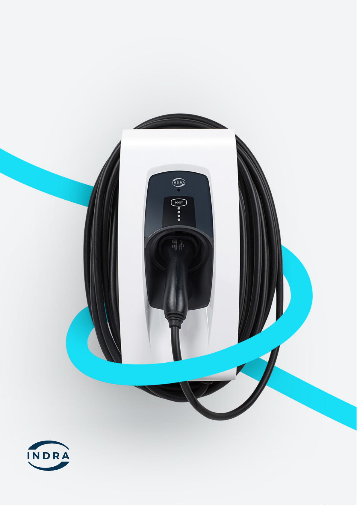
Indra Smart PRO Features
The Smart PRO is the most feature-rich EV charger available on the market, ensuring your EV
is always ready when you need it whilst maximising opportunities to charge from local solar
and from the Grid when it is cheapest to do so. The Smart PRO features a simple on-unit
interface and a supporting App that provides current status and historical information,
as well as enabling easy conguration of the unit.
The Smart PRO is fully compliant with all relevant standards and works with all EVs, those
available today and those coming in the future. It is quick and easy to install. The Smart PRO
comes with a 5-year warranty as standard, and will never let you down, ensuring you are
always charged and ready to go when you need to be.
Track your charging history to help
you make the most of your charger
Charge with solar. Make the
most of your panels.
Everything you need to know
about charging at your ngertips
Quickly start a boost
charge from the app
Flexible charging schedules
that t your needs perfectly
Set how much charge to add by miles,
kWh or cost. Or just do a full charge.
See your past charge history and spend
in the feature rich Indra App.
As a solar compatible EV charger, you can utilise
your free green electricity from your solar
panels to power your electric vehicle.
The Smart PRO automatically generates a
personal charging schedule each time you
plug-in based on your preferences to ensure
you’re always topped up.
Comprehensive and intuative help section
in the Indra App lets you get help whenever
you need it.
Smart scheduling allows the user to create
a schedule window, this is when the charger
will start and stop charging, but also, how
many miles to add, how many kWh to add or
how much money’s worth of energy to add to
the car.
Plans changed? The Smart PRO Boost feature
lets you temporarily override your schedule to
get your car fully charged as soon as possible.

7
O-PEN Fault Detection
The Smart PRO has built in O-PEN protection in the form of Indra’s patented PESTs. This
oers multiple options to comply with the PEN fault regulations, including Line to Neutral
Voltage monitoring (PEST mode B) and CPC to true earth voltage monitoring (PEST mode A).
House Fuse Protection (Load Curtailment)
Is a function that allows an EV charger to be installed at a property that may not have
enough spare power capacity to accommodate the charger always operating at full capacity.
It works by monitoring the amount of power the installation is using via an external CT clamp
and comparing that to the rating of the main fuse supplying the installation. If the dierence
is greater than 32A then the charger will oer full charge. If the dierence is less than 32A
then the charger will only oer as much power as there is spare capacity.
Note: G100.2 denes how load curtailment is managed. If the charger is congured to use
load curtailment and it loses contact with the External CT clamp, then the charger will
de-rate its power output to 6A to protect the main cut-out, thus 6A is the gure that should
be considered when carrying out the maximum demand survey.
DC Leakage Protection
An RDC-DD is tted into the Smart PRO oering 6mA DC leakage protection. This means the
Smart PRO can be installed with a Type A or Type F RCD up stream.
Over-The-Air Updates
The Smart PRO can be updated remotely while connected to the internet . These updates
can oer improvements to the function of the charger, be pre-emptive xes for known
issues, or used to rectify faults if they occur.
Tari Intelligence
Indra Smart Chargers can optimise charging based on the customer’s tari, where they have
a time of use tari. We support any time of use tari including Octopus Agile. For more
information follow this link here.

8 Indra Smart PRO Installation Guide
Solar Mode
This mode can be selected in the Indra App and can enable the customer to use surplus solar
energy (or any other form of micro-generation) to charge their car.
The external CT monitors how much energy is being exported from the installation. If the
installation is exporting more than 1.4kW , then the charger will oer the car a charge.
(1.4kW is the minimum amount of power required for all in-car chargers to accept a charge).
Note: The external CT clamp can only measure what energy is being exported back to the
grid, therefore, if the micro-generation is generating 2kW, and the installation is using 1kW,
the charger will only detect the remaining 1KW being exported to the grid. This means the
charger will not oer a charge to the car because there isn’t enough power to trigger the
in-car charger (1.4kW). Export to the grid needs to be 1.4kW or greater before the car will be
oered charge.
Smart Scheduling
Smart scheduling enables the user to create a schedule window, this is when the charger will
start and stop charging, but also, how many miles to add, how many kWh to add or how much
money’s worth of energy to add to the car.
Charge Analytics
The Indra App allows the user to control the charger, use the boost function, set charging
schedules, etc., and provides detailed information on their charging behaviour and their
charging history, including how much money they have spent, and how many miles-worth of
charge have been added to the car.

9
Specications
Electrical
Rated power 7.4kW
Charging current 6A-32A variable
Protection 6ma DC leakage detection
Standby consumption <5W
Compliance
CE Marked and UKCA
Standards and regulations The Electric Vehicles (Smart Charge
Points) Regulations 2021, BS EN 50581,
BS EN 60529, BS EN 61010-1, BS EN
61851-1, IEC 61851-21-2, IEC 61851-22,
BS 7671, BS 7671 Amendment 1, G100
Mechanical
Dimensions 200mm x 420mm x 130mm (WxHxD)
Weight 3.5kg
Operating Temperature -20°C to +50°C
Operating Humidity 5% - 95%
Enclosure Polycarbonate, IP66 rated
Protection IK10
Key features
Solar
matching
Quick
Boost
House fuse
Protection
Over-the-air
updates
Charging
schedule

10 Indra Smart PRO Installation Guide
PEN Fault, Earthing, Simultaneous Touch
(PESTs) ProtectionProtection
The Smart PRO PESTs solution can operate under four of the indents of BS 7671:2018
A1:2020+A2:2022; section 722.411.4.1, for the purposes of design/installation we have
two modes of operation which Indra call A & B. Mode A can be congured with or
without a reference electrode. The safest installation conguration is, mode A with
reference electrode.
• Mode A with reference electrode – Indent iii – PME (Protective Multiple Earthing) as
CPC with a reference electrode and the only method for compliant install on a 3-phase
installations. Using this method negates nuisance tripping from uctuating supply voltage.
• Mode B – Monitors the L-N voltage and will disconnect from the car if the voltage goes out
of range (253V-207V). PME is used as CPC and no earth rod or reference electrode is required
if there are no simultaneous contact or touch voltage risks present. Consideration should
be given to nuisance trips where the line to neutral voltage may regularly exceed 253v,
especially where local solar panel or other forms of micro-generation are present.
• Mode A without reference electrode – For installations that do not fall under the
requirements of 722.411.4. E.g.E.g., TT installations, indoor installations, installations where
PME is bonded to Earth in accordance with indent ii.
PESTs Mode A essentially works by comparing three voltage readings:
1. L - N (Disconnects above 257.6V and below 184V. 230v +/- 12%)
2. L - Ref Electrode (Disconnects above 257.6V and below 184V. 230v +/- 12%)
3. CPC (PME) – Ref Electrode (Disconnects above 30v RMS)
• Mode A without reference electrode – For installations that do not fall under the
requirements of 722.411.4. E.g., TT installations, indoor installations, installations where PME
is bonded to Earth in accordance with indent ii.
PESTs Mode A essentially works by comparing three voltage readings:
1. L - N (Disconnects above 257.6V and below 184V (230v +/- 12%)
2. L - Ref Electrode (Disconnects above 257.6V and below 184V (230v +/- 12%)
3. CPC (PME) – Ref Electrode (Disconnects above 30v RMS)

11

12 Indra Smart PRO Installation Guide
General Installation Notes
WARNING: FAILURE TO COMPLY WITH THESE INSTRUCTIONS COULD PRESENT A HAZARD
A. Indra Smart PRO must be installed by a qualied electrician who has completed Indra
Academy Training. Any servicing or tampering by a non-qualied professional
electrician will void the warranty.
B. Read these instructions fully before installing or using the Smart PRO.
C. The power supply to the Smart PRO MUST be isolated and checked for dead before
installation or maintenance.
D. The Smart PRO is designed for permanent installation and is suitable for operation on
an AC electricity supply having the same voltage and current rating as shown
on the product label.
E. The Smart PRO should be installed in accordance with existing wiring regulations.
F. The Smart PRO MUST NOT be tted alongside an upstream protection device which
claims to meet ident (iv) of BS 7671:2018+A1:2020+A2:2022; section 722.411.4.1.
Voltage upstream PEN Fault protection and curtailment devices may damage any
Smart PRO device through frequent removal of the grid supply under load.
WARNING: Protection against electric shock shall not be automatically reset.
G. The Smart PRO MUST be connected to CPC (either supplied from a TT electrode or
the PME earth.
H. The installation location MUST be structurally sound and MUST NOT be subject to
excessive. dust, vibration, lint, or other material build-up which could aect the
Smart PRO’s proper operation.
I. The customer should have agreed to the position of the charger, any additional
enclosures, and cable routing prior to installation.

13
Charger Layout

Pre-Installation Survey
Before installing an Indra Smart PRO, we recommend surveying the installation to ensure
that an install can go ahead and that the Smart PRO is appropriate for the requirements.
Therefore, you should:
• Identify the earthing arrangement of the property and the required PEST mode that
will be required.
o If a reference electrode will be required, identify a suitable location for it.
• Establish the maximum demand of the existing installation and compare this with
the rating of the main cut out supplying the property. If there is less than 32A
capacity remaining, then the Load Curtailment (House fuse protection) feature on the
Smart PRO will be required.
o If Load Curtailment or Solar Mode is required by the customer, establish where
the external CT would be placed.
• Identify which connectivity method would be most appropriate.
Installation Procedure
The Smart PRO is supplied with the screws and wall xings that are required to permanently
x it in position. However, it remains the responsibility of the installer to evaluate the
suitability of the installation surface and use the appropriate xings for each install.
• All parts of the existing installation that will comprise part of the EVSE charging
circuit, MUST be inspected for damage, suitably rated and compliant with the
appropriate regulations.
• Ensure the installation earthing conductors are tested and compliant with BS
7671:2018 A1:2020+A2:2022
WARNING: ANY DAMAGED OR UNSUITABLE CABLES OR EQUIPTMENT MUST BE REPLACED
• Inspect the Smart PRO to ensure the charger has not been damaged in transit and is
safe to connect.
14 Indra Smart PRO Installation Guide

15
Switchgear
The Indra Smart PRO does not have in-built RCD protection, which means it must be tted
upstream. Indra recommends installing the following to minimise potential nuisance
tripping and to ensure compliance with BS7671:2018 A1:2020+A2:2022 section 722. (These
requirements can be met in whatever conguration suits your design.)
a) Type A 30maA Double Pole RCD protection
b) C Curve 40A Overcurrent protection
In accordance with BS 7671:2018 A1:2020+A2:2022 Regulation 443.4.1, a surge protection
device will need to be installed to protect the charger unless the customer has signed a
waiver acknowledging they accept the risk of any potential damage caused.
Choosing the charger Location
• Select an installation location that ensures future servicing of the Smart PRO, where
the back plate can be mounted ush to a at wall and screws can be used to
permanently secure the charger in position.
• Make sure the install location will not allow any ammable material to come within
100 mm of the unit.
• The control panel of the unit should be installed between 0.75-1.20m from the ground.
• The charger should be placed such that the potential risk of tripping over trailing
charging leads is minimised as far as reasonably practicable.

Wall Mounting
Note: The xing holes in the bracket are spaced to meet standard brick sizes so they can all
fall within a brick centre.
• Oer the mounting bracket against the surface you intend to x to and level using a
spirit level
• Mark and drill four holes with a 6 mm drill bit (Masonry/+.5mm Plasterboard)
• Fit the supplied wall plugs into the holes and secure the bracket with the four screws
supplied.
Hanging the charger
• Hold the top of the charger just above the wall bracket tilted upwards away from the
wall
• Lower the charger onto the two prongs at the top then hinge the charger back ush
with the bracket
• Secure the charger to the bracket by tting 2 x 4x8mm button head, T20 Torx screws
into the bottom of the charger with a T20 screwdriver. Torque setting 2.0-2.5 N/m.
• Carefully remove the front of the charger and hinge it to the side to allow access, the
front body Is secured to the main body to protect the ribbon cable to the front panel.
16 Indra Smart PRO Installation Guide

17
Cable Entry
The Smart PRO is designed with four cable entry points, two in the bottom edge and two in
the rear (Identied in blue on Fig 01).
• Cable entry point 1 is designed for a 25mm hole
• Cable entry point 2 is designed for a 20mm hole
• The rear entry points are designed for a 25mm hole
• Install the appropriately sized IP68 rated gland for the cable used, or, for rear entry,
enter using a method that will ensure the IP rating of the enclosure.
All swarf and shavings should be removed from the charger and the hole deburred.

Connect Mains Cables
• Remove the outer insulation of the cable, leaving 10mm showing at the gland
• Cut the cables to approximately the following lengths:
o Live – 200mm
o Neutral – 200mm
o CPC – 240mm
o Data Cable (For CT only) -180mm
o Data Cable (For Internet) – 400mm
• Route the wires as per Fig: 02
• Insert wires into the lever type connectors labelled L (Live), N (Neutral) and CPC
(Circuit Protective Conductor)
Note: Indra recommends the use of bootlace ferrules on class 5 & 6 cables ONLY
Note: Indra recommends using EV Ultra Cable from Doncaster Cables as is contains
power and data in the same cable.
18 Indra Smart PRO Installation Guide

19

Installing a Reference Electrode
When operating under PEST mode A, a reference to true earth may be required to protect
against O-PEN faults in the distribution network. This reference allows for voltage to be
measured between the installation earth (CPC) and true earth, so that if CPC becomes live
because of a broken PEN this will be detected and the charger will disconnect Live, Neutral
and CPC from the car.
The reference electrode is NOT serving as a fault path, thus does not need to comply with
the requirement for a TT earth electrode.
The reference electrode should be a copper plated 3/8” electrode with a lug terminal clamp.
• If installing straight into soil or equivalent soft terrain, then the electrode can be cut
down, to reduce the necessary length driven into the ground (as short at 300mm). For
hard aggregate, the full four-foot length may have to be maintained.
Before driving the electrode into the ground, ensure there are no buried services in the area.
• Using a lump hammer, or similar, drive the electrode straight into the ground. Leaving
enough length at its tip to secure the clamping terminal.
• Attach the lug clamp terminal and run a length of cable (clipping against walls where
necessary) back to the Smart PRO unit; terminate in the lever type connector labelled
“REF”
Note: Indra recommend the use of Solar PV cable (EN5061) with double insulation
• Using a Multi-Function Tester or electrode tester, measure the resistance of the newly
installed reference electrode and ensure it is less than 600Ω.
20 Indra Smart PRO Installation Guide
Other manuals for Smart PRO
5
Table of contents
Other INDRA Batteries Charger manuals