Industrial Scientific DSX User manual

Product
Manual
DSX Standalone Mode
DSXi Cloud-connected Mode
iNet® Accounts
Edition: 6
June 5, 2020
Part Number: 17156005-1

Industrial Scientific Corporation.
Pittsburgh, PA USA
Shanghai, China
© 2015, 2016, 2017, 2018, 2019, 2020 Industrial Scientific Corporation
All rights reserved. Published 2020
Revision 6

Contents
Warnings and Cautionary Statements .............................................................................................................................................. 1
General Information .......................................................................................................................................................................... 3
Introduction ....................................................................................................................................................................................... 3
Capabilities ....................................................................................................................................................................................... 3
DSX Standalone Mode ..................................................................................................................................................................... 3
DSXi Cloud-connected Mode............................................................................................................................................................ 4
iNet Accounts.................................................................................................................................................................................... 4
Compatibilities................................................................................................................................................................................... 5
System Requirements and Supplies................................................................................................................................................. 5
Certifications ..................................................................................................................................................................................... 5
Care and Operating Guidelines ........................................................................................................................................................ 6
Training............................................................................................................................................................................................. 6
Getting Started.................................................................................................................................................................................. 7
Work-space Checklist ....................................................................................................................................................................... 7
Unpack.............................................................................................................................................................................................. 7
Hardware Overview .......................................................................................................................................................................... 9
Specifications.................................................................................................................................................................................. 10
Physical Specifications ................................................................................................................................................................... 10
Performance Specifications ............................................................................................................................................................ 10
Setup............................................................................................................................................................................................... 11
Introduction ..................................................................................................................................................................................... 11
Setup Instruction............................................................................................................................................................................. 11
Use.................................................................................................................................................................................................. 19
Instrument docking orientation........................................................................................................................................................ 19
Use Instruction................................................................................................................................................................................ 20
Error Messages............................................................................................................................................................................... 22
Warranty and Limitation of Liability ................................................................................................................................................. 25
Contact Information......................................................................................................................................................................... 26


1
Warnings and Cautionary Statements
Failure to perform certain procedures or note certain conditions may impair the performance of this
product. For maximum safety and optimal performance, please read and follow the procedures and
conditions listed below.
Use only in a clean-air environment known to be nonhazardous.
Use of this product in areas where it may be subject to large amounts of electromagnetic
interference may affect the reliable operation of this device and should be avoided. Sources of
large amounts of interference could be and are not limited to:
Operation near high radio frequency (RF) fields (near 2-way radio transmission antennas where
the RF fields may greatly exceed 10 V/M, etc.).
AC Power Mains that may have excessive power surges, spikes, or transients (from large AC
motors operating heavy loads, which may induce voltage sags, etc.).
Use only at altitudes below 2,000 m (6,000 ').
NOTE: This product has been tested to, and passes all EMC requirements to EN 61326-1:2013
Electrical Equipment for Measurement, Control and Laboratory Use for Type 2 (Industrial)
Apparatus, as well as FCC Part 15, Class A emissions levels when installed to the requirements
outlined within this manual. Mandatory compliance to these standards helps to ensure controlled,
reliable operation of this device when exposed to typical levels of electromagnetic interference as
well as ensuring that this device is not the source of emissions that might interfere with other
equipment installed nearby.
NOTE: Per 30 CFR 75.320(b), the product tests for oxygen deficiency of MSHA-approved oxygen
detectors compatible with the product that can detect 19.5% oxygen with an accuracy of ±0.5%.
NOTE: Per 30 CFR 22.7(d)(2)(i), the acceptable limit during calibration and bump testing with
2.5% methane must be 10% for MSHA-approved instruments using Industrial Scientific certified
calibration gas.
NOTE: This product has an internal pump that controls the flow of gas delivered to the system. As
a result of the internal pump, a demand-flow regulator must be used in conjunction with this
product.
Higher wind speeds and areas that use strong ventilation systems can dilute calibration gases
during zeroing, bump testing, and calibration.
Notice: The software associated with this product contains open source components. To obtain licensing
and related information about these components, click here.


2
General Information
Introduction
Capabilities
Compatibilities
System Requirements and Supplies
Certifications
Care and Operating Guidelines
Training
Introduction
The DSX™Docking Station can be installed for use with the gas detection instruments and program
platforms of Industrial Scientific. Within this manual, the docking station is referred by order type or the
references noted below:
Order type
Reference
DSX Standalone Mode
Standalone Mode (unit, order, etc.)
DSXi Cloud-connected Mode (DSXi)
DSXi (unit, order, etc.)
DSX-to-DSXi upgrade (DSXi)
DSXi (unit, order, etc.)
iNet®Account (replacement or add-on equipment)
iNet Account (unit)
Capabilities
The DSX Docking Station order types named above each provide the following.
•Choice of 3 or 6 gas intake ports
•Charging of compatible instruments
•Choice of display-screen language: English, French, German, Portuguese (Brazilian), or Spanish
•Automated and on-demand (“forced”) bump tests and calibrations
Each order type offers additional functionality as summarized below.
DSX Standalone Mode
Automatically performs one on-dock task (bump test [default setting] or calibration).
When a USB data storage device (included) is connected, the following are automatically downloaded to
the device when an instrument is docked:
•Records for station-performed bump tests
•Records for station-performed calibrations
•Instrument data logs

4
Downloaded data are saved to the USB in CSV (comma separated values) file format, which can be
opened with (or imported to) a spreadsheet.
DSXi Cloud-connected Mode
Automatically performs all scheduled instrument tasks on-dock including bump tests, calibrations,
firmware updates, and settings changes.
Instrument data logs and station-performed bump tests and calibrations are automatically uploaded to
the cloud-based Gas Detection Program Platform, iNet Control.
Access to the iNet Control software interface, which provides these capabilities:
•View your gas detection program summary and learn of specific issues that need attention.
•View alarm events, other instrument data, reports, and alerts.
•Basic account administration including global (fleet) event settings and special events.
•Organizational tools to create equipment groups and assign settings to equipment groups or
equipment items.
•Set up users for iNet Control access and the automatic receipt of reports and alerts; limit or expand
a user’s access level.
Docking station firmware and iGas®cylinder compatibility data are automatically updated.
iNet Accounts
Automatically performs all scheduled instrument tasks on-dock including bump tests, calibrations,
firmware updates, and settings changes.
Instrument data logs and station-performed bump tests and calibrations are automatically uploaded to
the cloud-based Gas Detection Program Platform, iNet Control.
Access to the iNet Control software interface, which provides these capabilities:
•View your gas detection program summary and learn of specific issues that need attention.
•View alarm events, other instrument data, reports, and alerts.
•Basic account administration including global (fleet) event settings and special events.
•Organizational tools to create equipment groups and assign settings to equipment groups or
equipment items.
•Set up users for iNet Control access and the automatic receipt of reports and alerts; limit or expand
a user’s access level.
Docking station firmware and iGas cylinder compatibility data are automatically updated.
All iNet docking stations and instruments are leased from and maintained by Industrial Scientific. When
an equipment item is in need of service, iNet Control notifies the account administrators, removes the
item from service, and ships a replacement item.

5
Compatibilities
Each docking station is compatible with one of the following Industrial Scientific instruments:
•GasBadge®Pro
•MX6 iBrid®Multigas Monitor
•Tango®TX1 Single-gas Monitor
•Ventis®LS Multigas Monitor
•Ventis®MX4 Multigas Monitor
•Ventis®Pro4 Multi-Gas Monitor
•Ventis®Pro5 Multi-Gas Monitor
•SafeCore®Module (used with Radius®BZ1 Area Monitor)
The docking station is compatible with only iGas cylinders used with demand-flow regulators and card-
reader-and-tubing assemblies, all from Industrial Scientific. The use of demand-flow regulators that have an
iGas pressure switch is recommended for DSXi units and required for iNet Accounts.
The adapter tubing assembly (part number 17156572) must be used with the aspirated SafeCore Module.
DSXi units are compatible with iNet for the cloud-based storage of and access to data. Standalone Mode
units use a USB storage device for data storage and access, and can be used with PCL3 compatible
printers.
System Requirements and Supplies
DSX Standalone Mode
A PC and Ethernet cable is recommended for setup.
DSXi Cloud-connected Mode and iNet Accounts
A network connection is required for setup and operation.
The network connection must provide 10/100 Ethernet support using a Cat5 (or greater) Ethernet cable
with RJ45 connectors. For longer cables, 14−110 m (46–360 '), use a solid conductor shielded twisted pair
Ethernet cable.
The docking station does not natively support wireless networking. If a wireless connection is desired, it can
be established through third-party hardware solutions such as wireless bridges or mobile broadband
routers plugged into the unit’s LAN port. Use of such a wireless solution will not affect docking station
operation.
Certifications
The product is certified for use as indicated on the labels affixed to the docking station.

6
Care and Operating Guidelines
Use the following guidelines to enhance personal safety and the protection of the docking station and
working environment.
The unit should be serviced by qualified personnel only. Contact Industrial Scientific for Technical Support,
troubleshooting, or repair service.
The unit is equipped with a fixed-voltage power supply and will operate at only one voltage (see the
regulatory label on the outside of the unit for its operating voltage). To help protect the unit from sudden,
transient increases or decreases in electrical power, use a surge suppressor, line conditioner, or
uninterruptible power supply (UPS).
To reduce the risk of electric shock or fire:
•Do not use the unit during an electrical storm without proper protection.
•Do not connect or disconnect any cables to or from the unit during an electrical storm.
•Do not expose the unit to rain or moisture.
•Do not push any objects into the openings of the unit.
To avoid possible damage to the unit's system board, wait 5 seconds after powering off the unit before
restarting. To avoid shorting the unit when disconnecting a network cable, first unplug the cable from the
unit, and then from the network jack. When connecting a network cable, first plug the cable into the network
jack, then the other end into the unit.
Be sure nothing rests on the unit's cables or tubing and that the tubing is not kinked. Ensure cables and
tubing are not located where they can be stepped on, tripped over, loosened, disconnected, or cut.
•Do not place the unit on or near flammable materials.
•Do not use corrosive chemicals or vapors near the unit.
•Do not immerse the power cable or plug in water.
•Do not drop the unit.
Before cleaning the unit, disconnect the power supply from the power source.
•Clean the unit with a soft cloth dampened with water.
•Do not spray water directly onto the unit.
•Do not use liquid or aerosol cleaners, which may contain flammable substances.
Compressed gas cylinders and their contents may present specific hazards to the user. Use only in a well-
ventilated area. Use only in accordance with the instructions and warnings as marked on the cylinder and
the appropriate Material Safety Data Sheet (MSDS) or Safety Data Sheet (SDS).
Training
Industrial Scientific offers classroom and self-guided online training options for a variety of topics, including
the setup and operation of the docking station. For more information, visit the Training section of the
Industrial Scientific website, www.indsci.com.

3
Getting Started
Work-space Checklist
Unpack
Hardware Overview
Specifications
Work-space Checklist
✓Set up and use the docking station in an area that is known to be nonhazardous.
✓Choose a work space that is large enough to accommodate the unit and its accessories with an
accessible power source.
✓For DSXi and iNet Account units, choose a work space that is in close proximity to a network
connection; for DSX Standalone Mode units, a computer connection.
✓As needed, mount cylinder holders to the desired desk or wall locations.
✓Abide by all care and operating guidelines during setup and operation.
Unpack
The box contains those items listed and shown below (as ordered). Each ordered item should be
accounted for in the unpacking process.
After unpacking, if any item is missing or appears to have been damaged, contact Industrial Scientific or a
local distributor of Industrial Scientific products.
Item (part number)
DSX Docking Station
•GasBadge®Pro (18109331)
•MX6 iBrid®(18109329)
•SafeCore®Module (18109396)
•Tango®TX1 (18109330)
•Ventis®LS (18109328)
•Ventis®Pro4, Ventis®Pro5, and Ventis®MX4 (18109327; diffusion model shown here)
8
Item (part number)
iGas Card-reader-and-tubing assembly (18105684)
Cable retainer rubber pads and cable ties (17156905-1)
Power supply (17136623)
With adapters for Australia, Europe (Europlug), North America, and UK and Ireland
Power cord, dedicated (optional; use with power supply in place of adapter)
•Australia (17155001)
•Europe [Europlug] (17155003)
•North America (17155000)
•UK and Ireland (17155005)
Fresh-air fitting (factory installed)
USB data storage device (17157119; for DSX Standalone Mode orders only)
Diffusion insert (18109547; for Ventis Pro4, Ventis Pro5, and Ventis MX4 diffusion
instruments only)
Aspirated insert (18109548; for Ventis Pro4, Ventis Pro5, and Ventis MX4 aspirated
instruments only)
9
Hardware Overview
Front (Ventis Pro Series and Ventis MX4 diffusion model shown)
Hood
Spring hinge
Cradle
LCD
LED lights
•green
•amber
•red
Keypad
From left to right:
left arrow key (), enter key (),
and right arrow key ()
Back Back panel (six port-set unit shown)
iGas cable retainer
iGas port sets
From left to right:
Port set 4
Port set 5
Port set 6
Power supply port
(12 VDC)
Network connection
(LAN port)
From left to right:
Port set 1
Port set 2
Port set 3
Note: Port sets 1, 2, and 3 are
positioned in the same location
on the three port-set unit.
USB port, type A
(USB)
For use with Standalone
Mode units (USB data
storage device or
compatible printer)
iGas cable retainer

10
Specifications
Physical Specifications
Instruments supported
GasBadge®Pro, MX6 iBrid®, SafeCore®Module, Tango®TX1, Ventis®LS , or
Ventis®Pro4, Ventis®Pro5 and Ventis®MX4
Dimensions
GasBadge Pro, Tango TX1: H: 22.66 cm (8.92 "); W: 18.1 cm (7.13 "); D: 30.22
cm (11.9 ")
Ventis Pro4, Ventis Pro5, Ventis MX4:
Aspirated: H: 27.94 cm (11 "); W: 17.78 cm (7 "); D: 30.48 cm (12 ")
Diffusion: H: 25.4 cm (10 "); W: 17.78 cm (7 "); D: 30.48 cm (12 ")
Ventis LS: H: 24.97 cm (9.83 "); W: 18.1 cm (7.13 "); D: 30.22 cm (11.9 ")
MX6 iBrid: H: 25.3 cm (9.96 "); W: 18.1 cm (7.13 "); D: 30.22 cm (11.9 ")
SafeCore Module: H: 27.3 cm (10.75”); W: 18.1 cm (7.13”); D 32.12 cm (12.65”)
Gas and fresh-air intake ports
3-port configuration: two gas and one fresh air
6-port configuration: five gas and one fresh air
Pump flow rate
1.2 SCFH (550 mL/min)
Communication
10/100 Ethernet support using a Cat5 (or greater) Ethernet cable with RJ45
connectors (for longer cables, 14−110 m [46–360 '], use a solid conductor
shielded twisted pair Ethernet cable).
USB port for data storage device or printer (for use with Standalone Mode units
only).
Display
128 x 64 dot matrix LCD
Language options: English, French, German, Portuguese (Brazil), or Spanish
Performance Specifications
Operating temperature range
0–50 ºC (32–122 ºF)
Operating humidity range
0–80% relative humidity (RH) up to 30 ºC (86 ºF), decreasing linearly to 50% RH
at 50 ºC (122 ºF)
External power supply ratings
Supply voltage: 100–240 VAC/12 VDC
Frequency range: 50–60 Hz
Current rating: 5A

4
Setup
Introduction
Setup Instruction
Introduction
Based on your order type, complete the instruction steps
noted below. It is important to complete these tasks in the
stated order.
Order type
Complete these
steps*
DSX Standalone Mode
2–20
DSXi Cloud-connected Mode
1A and 2–18
DSX-to-DSXi upgrade
1B and 2–18
iNet Account (replacement or add-on
equipment)
2–18
*If the docking station will be dedicated to service only Ventis Pro
Series and Ventis MX4 units, also complete step 21.
When setup is completed, your docking station will look
similar to the image shown here. It may differ based on the
number or type of connected cylinders and whether the unit
is or is not connected to a network or computer. If you have
any questions during setup, contact Industrial Scientific.
Setup Instruction
Step
Task
1
Activation
To activate a DSXi Cloud-connected unit or a DSX-to-DSXi upgrade unit:
a. Go to www.indsci.com/mydsx
b. Follow the on-screen prompts to activate your DSX Docking Station and request access to your iNet Control account.
Note: The Docking Station serial number (S/N) is required for activation. The S/N is printed on a sticker located on the
back of the unit (S/N also displays on screen when the unit is powered on).
c. To install additional units, log into iNet Control. Click on the “Fleet” tab: from the drop-down menu, select “Activate a
Docking Station” and follow the on-screen instructions.
12
The remaining setup steps are shown below in detail. Those pertaining to the back of the docking station
(steps 2-18) can also be viewed as part of a completed docking station setup on page 18.
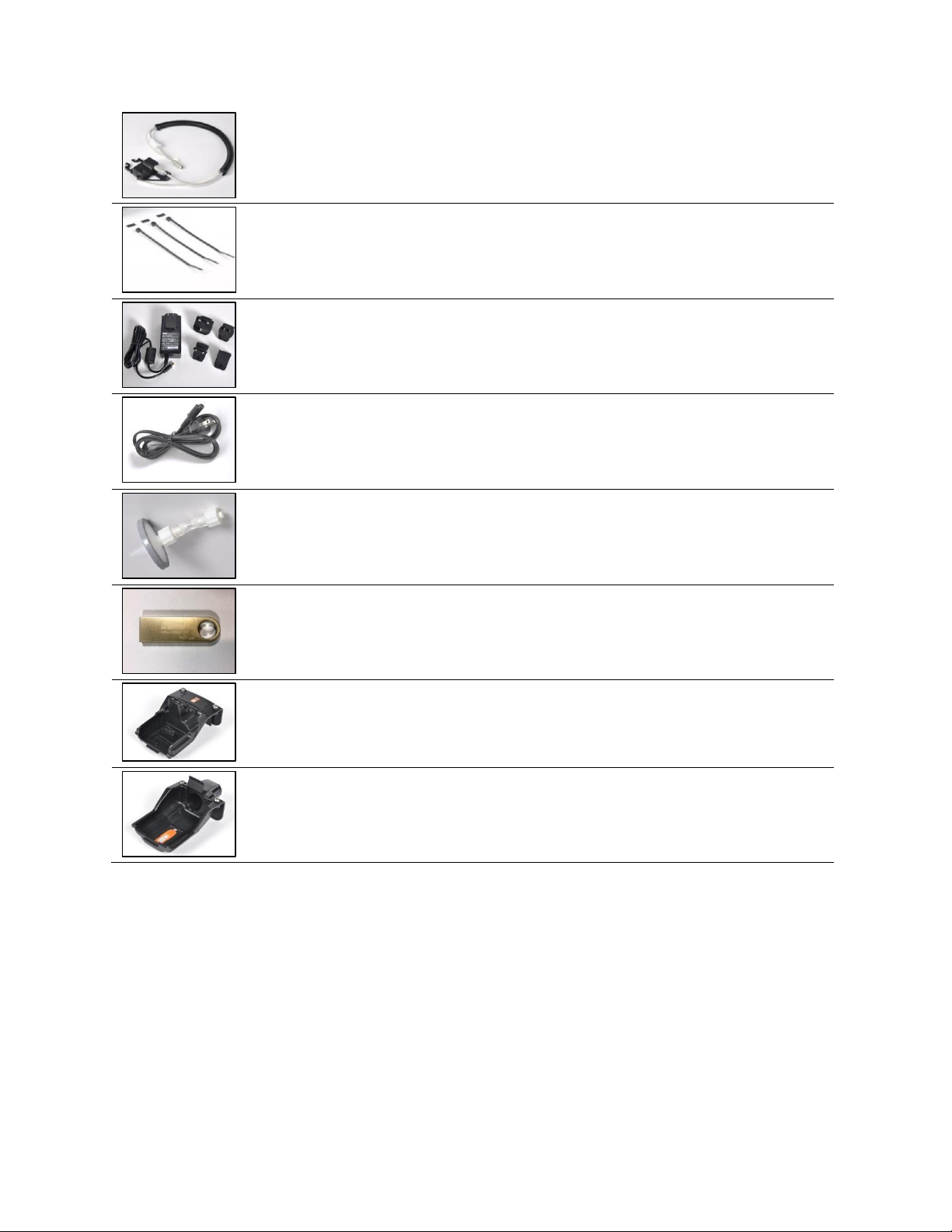
2
iGas Cable Retainer Setup
The docking station comes with three adhesive-
backed rubber pads and three cable ties. They are
used to prevent movement of the iGas cables
while they are connected to the docking station.
Install the adhesive-
backed rubber pads into
the recessed areas of the
cable retainer.
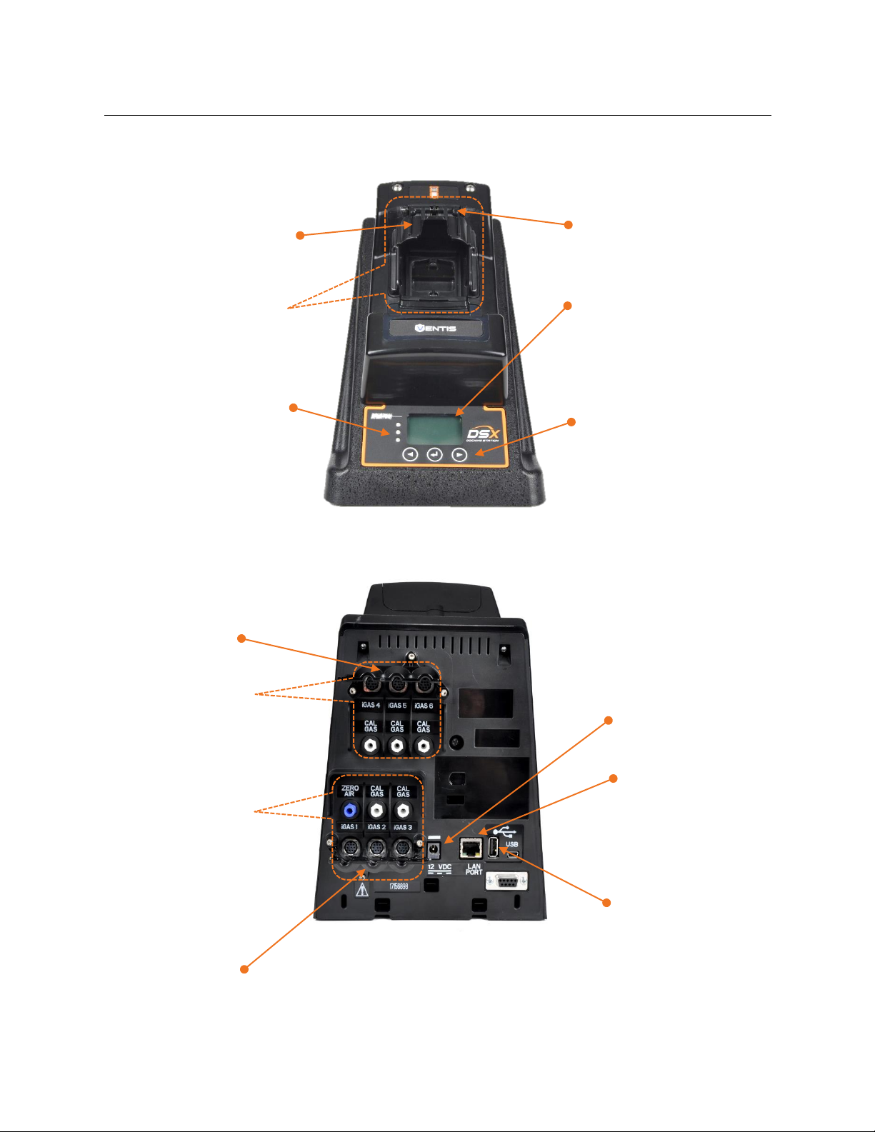
3
Network connection for DSXi units and iNet Accounts
PC connection for Standalone Mode units
For DSXi units and iNet Accounts, a network
connection is required for setup and operation.
For Standalone Mode units, a PC connection is
recommended for setup. This allows you to access
and adjust the unit’s settings through the on-board,
easy-to-use DSX Configurator. For example, you
can change the unit’s date and time setting to
match your time zone so that bump test and
calibration records have accurate date-time
stamps. Once setup is completed, Standalone
Mode units can be disconnected from the
computer.
─
Plug the cable into the
Network (or PC for
Standalone Mode orders).
Connect the other end to
the docking station’s LAN
port.

13
4-8
Start-up
The docking station comes with a power supply and plug adapters. If ordered, a dedicated power cord
can be used in place of the adapter, an option that works well with narrow power strips. Instruction is
provided for using either option.
4. Connect the power
supply to the docking
station’s 12 VDC port.
5. From the other end of the
power supply, remove its
cover: press the release tab
and slide the cover in the
direction indicated. Store the
cover for possible future use.
6. In the manner the cover was removed, replace it with the
adapter that is suitable for your outlet (above left). If a
dedicated power cord was ordered, use it in place of the
adapter (above right).
There is no power switch on the docking station. The unit is powered on and off at the power source.
─
7. Plug the power cord into a suitable outlet.
8. Check the docking station’s display panel.
A series of start-up messages appear on the docking
station’s display screen to indicate the unit is receiving
power.
The LED lights turn on to verify they are functioning and a
chirp will sound.
Note: If the unit doesn’t power on, check the power connections at
the back of the unit, power supply, and power source.
When start-up is successfully completed, the green LED light
will be on and the “ready screen” should display this text:
•For Standalone Mode units, “Standalone” (above right).
•For DSXi units and iNet Accounts, “Docking Station” and “√
iNet” (above left). Note: If these messages don’t display within
15 minutes, the unit is not cloud-connected. DSXi users,
recheck the work you did in Step 1, “Activation”. For iNet
accounts, contact Industrial Scientific.
i
iGas port sets
Each docking station features three (shown here)
or six port sets.
A port set comprises two items that are vertically
aligned, a numbered cable port (labeled iGAS X,
where X=1, 2, 3, 4, 5, or 6) and a corresponding
intake port for tubing.
•Use the port set iGAS 1 for air only. Its intake
port is labeled ZERO AIR and is blue in color.
•Use the port sets iGAS 2 through iGAS 6 for
calibration gas. Each set’s intake port is
labeled CAL GAS and is white in color.
intake port
for tubing
cable port
Fresh air port set
Calibration gas port set
Close-up of port sets 1, 2, and 3
Standalone
123.456.321.654
Charging
✓iNet
SN: 101231B-123

14
9
Fresh-air fitting
The fresh-air fitting is installed at the factory and is connected to the blue intake
port labeled ZERO AIR (shown here). The corresponding iGAS 1 cable port is
not used with the fresh-air fitting.
If your application uses a fresh-air fitting, go to step 10.
If your application does not use a fresh-air fitting and requires a zero-grade-air cylinder, remove
the fresh-air fitting: turn its white swivel connector counterclockwise.
10-18
iGas cylinder connections
The docking station is compatible only with iGas cylinders that
are equipped with demand-flow regulators. Each compatible
cylinder is connected to the docking station using an iGas card-
reader-and-tubing assembly (assembly; shown at right).
Whether it contains calibration gas or zero-grade air, each
cylinder is connected to its port set in the same manner.
•Connections for a calibration gas cylinder are shown and
described below using the port set, iGAS 2−CAL GAS.
•If you are connecting a zero-grade-air cylinder, follow the
instructions below, but use the port set iGAS 1−ZERO AIR.
Depending on site needs, each calibration-gas port set can be
connected for use or left disconnected when not needed. The
air port set should always have either the fresh-air fitting or a
zero-grade-air cylinder connection.
Note: The docking station will recognize any incompatible cylinders on connection
and will indicate the error on the display screen. A Standalone Mode unit will
recognize the compatible cylinders contained in its memory, which can be updated
by contacting Industrial Scientific.
Tubing and cable (connect to docking station)
Card reader (connects to cylinder’s card)
iGas Card-reading-and-tubing assembly
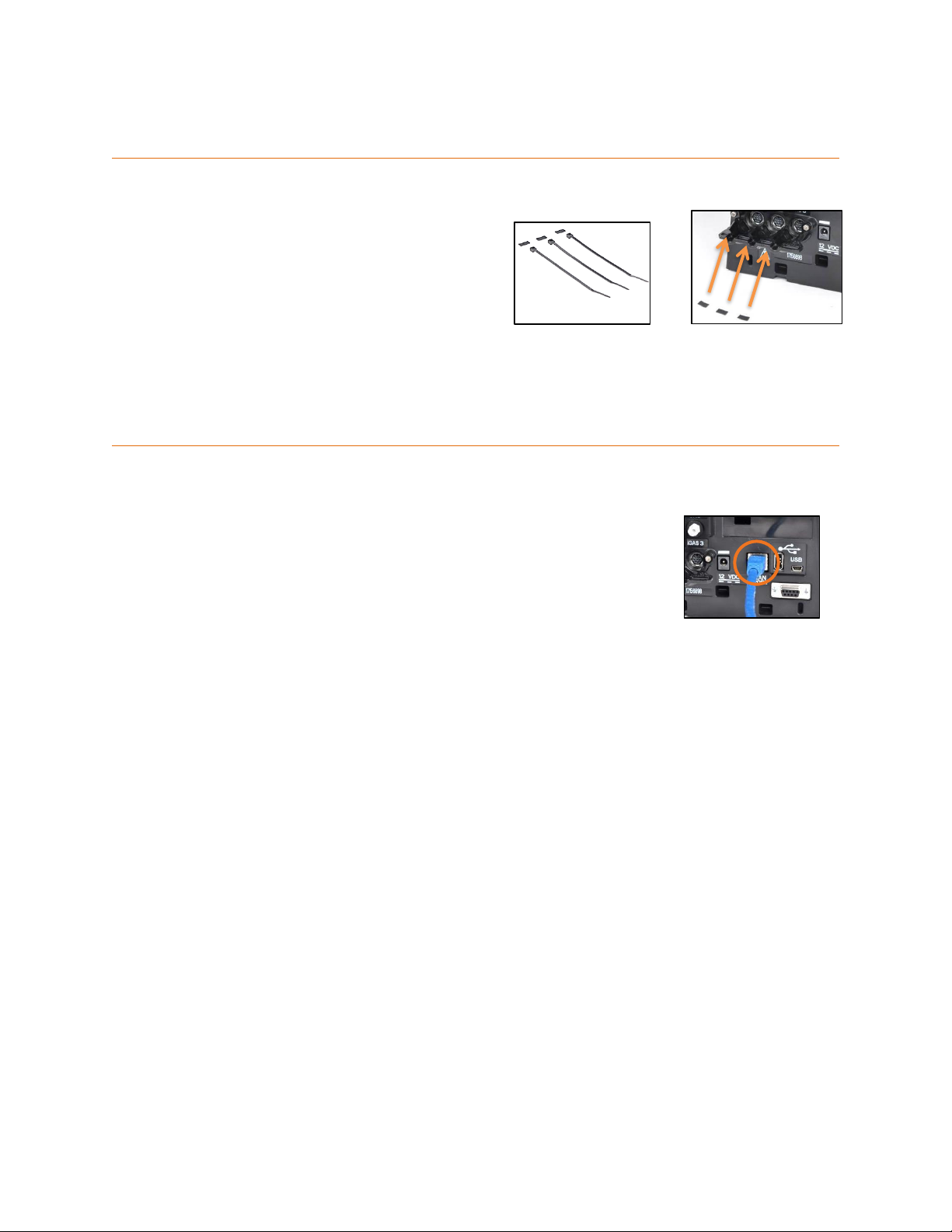
10. Attach the appropriate
demand-flow regulator to
the cylinder. Turn the
cylinder clockwise to
tighten.
11. Slide the iGas card,
which is attached to the
cylinder, into the assembly’s
card reader.
12. Attach the open end of
the assembly’s tubing to the
regulator nipple.
13. If the regulator is
equipped with a pressure
switch (recommended for
DSXi units and required for
iNet Accounts), plug its tab
into the slot on the side of
the card-reader.
15
14. Plug the cable
connector (arrow faces up)
into the iGAS 2 cable port.
15. From underneath the
retaining bracket, insert the
narrow tip of the cable tie
through the hole to the right
of the cable being secured.
Feed the cable tie over the
cable, then down through the
hole on the left side of the
cable. Guide the tip through
the fastener head.
16. Pull the cable tie to
tighten the cable securely into
position.
17. Trim the excess.
18. Attach the tubing's white
swivel connector to the CAL
GAS port located directly
above the iGAS 2 cable
port. Turn clockwise to
tighten.
Important!: Do NOT “cross-connect” any assembly’s tubing and cable to two different port sets! The docking station will not recognize this
and bump test and calibrations will fail.
Repeat steps 10-18 to connect additional calibration gas cylinders using the port sets iGAS 3, 4, 5, or 6.
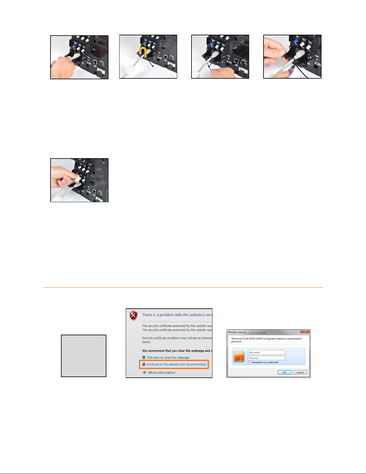
19
Settings for DSX-i and Standalone Mode units ONLY
19.1 Find the unit’s IP address
displayed on the “ready”
screen (123.456.321.654
shown here).
Open a web browser and enter
https:// followed by the unit’s IP
address and press enter.
19.2 At the security warning window,
choose the option that allows you to
continue. This device web site uses a
certificate signed by Industrial Scientific.
Note: This option may not be
recommended.
19.3 In the security dialog box, for user
name enter DSX, for password enter the
unit’s serial number (e.g. 101231B-123,
case sensitive). Click on OK. You will be
prompted to change the password before
continuing.
The DSX Configurator will open.
Standalone
123.456.321.654
Charging
✓iNet
SN: 101231B-123

16
19.4 Click on the configurator’s
Standalone tab.
Set the date and time (24-hour
format). Click on Set Clock.
Set the on-dock task (bump
test, calibration, or none).
Enable the Download Data log
feature with a checkmark
(recommended). This enables
the automatic download of a
docked instrument’s data to a
connected USB data storage
device. To disable this feature
(not recommended), click on
the box to remove the
checkmark.
Click on Save.
19.5 Click on the configurator’s
Information tab.
From the Language drop-down
menu, choose the desired
language for the docking
station display.
The Audible alarm feature is
enabled with a checkmark and
causes the docking station to
alarm when an instrument is
docked. To disable this feature,
click on the box to remove the
checkmark and turn off the on-
dock alarm.
When the Menu Locked option
is enabled with a checkmark,
the docking station cannot be
used for on-demand tasks.
Click on Save & Reboot.
19.6 After the docking station reboots, you may disconnect it from the computer for Standalone Mode operation.
Other manuals for DSX
2
This manual suits for next models
1
Table of contents
Other Industrial Scientific Docking Station manuals


