iNels eLAN-RF-Wi-003 User manual

Page 1of 15
eLAN-RF-Wi-003
Webové rozhraní / rev.3

Page 2of 15
eLAN-RF-Wi-003
Webové rozhraní / rev.3
1. Introduction..................................................................................................................................... 3
2. Logging in to the web interface eLAN-RF-Wi-003 ........................................................................... 4
3. Settings............................................................................................................................................ 5
Description of configuration panel...................................................................................................... 6
Description of functions ...................................................................................................................... 7
Adding RF actuators to the floorplan ................................................................................................ 15
Controlling RF units ........................................................................................................................... 15
Starting up scenes ............................................................................................................................. 15

Page 3of 15
eLAN-RF-Wi-003
Webové rozhraní / rev.3
The instruction manual provides information on installing and operating the device. The instruction manual is
always a part of the supply. Only perform installation after becoming thoroughly familiar with this User Guide and
device functions. Problem-free function of the device also depends on the way it was shipped, stored and
handled. If you notice any signs of damage, deformation, malfunction or a missing part, do not install this product
and return it to the point of sale. At the end of its service life, the product and its parts must be treated as
electronic waste. Before starting the installation, make sure that all wires and connected parts are not under
voltage. When assembling and performing maintenance, you must uphold safety regulations, standards,
directives and special provisions for working with electrical equipment.
1. Introduction
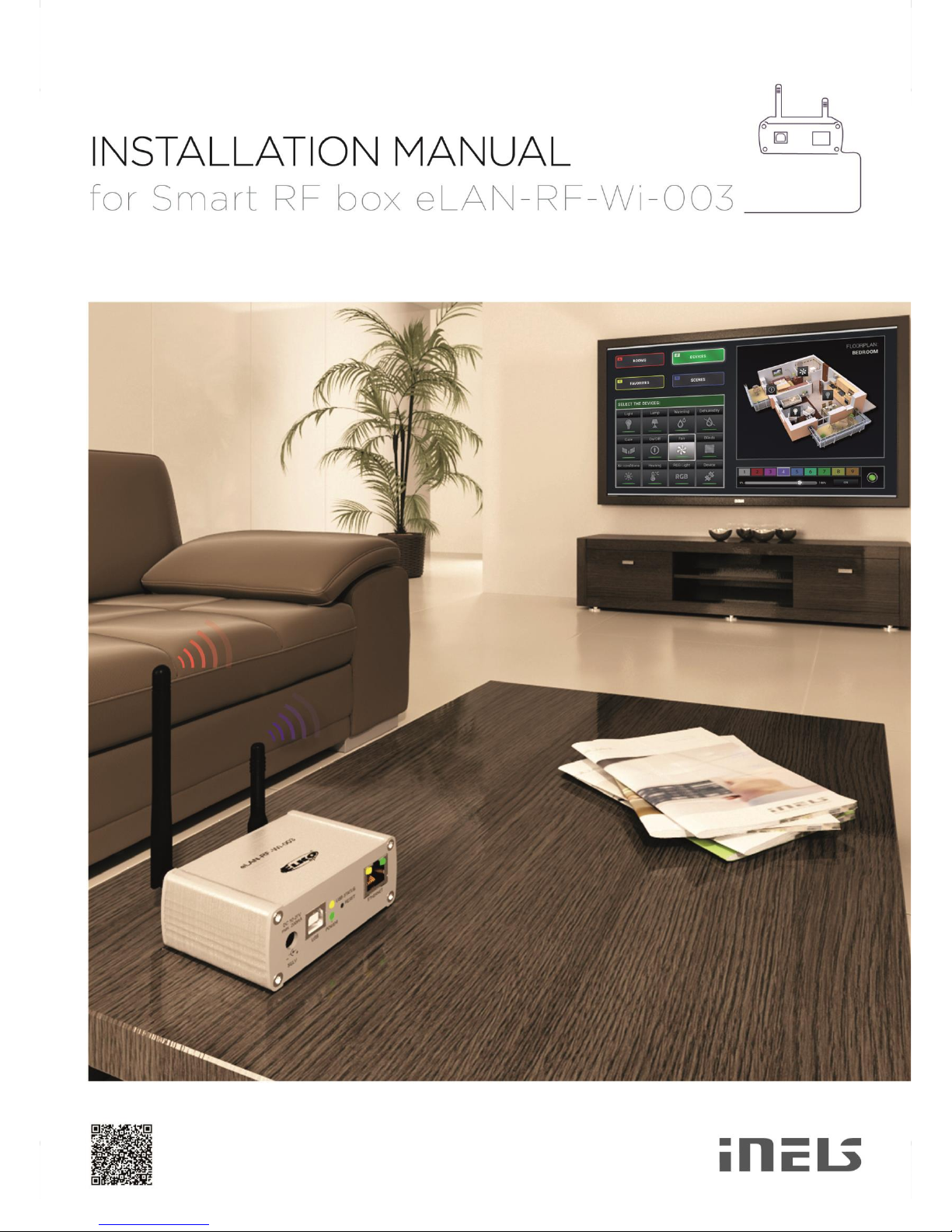
Congratulations on purchasing the Smart RF box eLAN-RF-Wi-003 control unit, an element of the RF
Control wireless system.
• The smart RF box enables you to control your electrical installation by smartphone, tablet or SMART
TV.
• It transmits and receives commands of up to 40 units, and it processes set programs for automatic
control, (you can gradually expand installation from 1 unit iNELS RF Control).
• Thanks to bi-directional communication, it visualizes the current status of individual units.
• The smart RF box eLAN-RF-Wi-003 is connected to the home network (router) via the Wi-Fi network
and communicates with your smart phone. Connection to the home network is also possible via
network LAN cable..
• The intuitive application environment offers central control from one place.
• Function of application iHC-MARF / iHC-MIRF:
- control of hot water or electric underfloor heating
- measuring temperature by wireless sensors
- switching appliances (garage door, blinds, fan, sprinklers, sockets, etc.)
- dimming lights (LED, energy-saving, halogen or classic lamps)
- time switching (delayed switching off of light when leaving room)
- video camera integration
- scenes (make multiple commands at once with a single press).
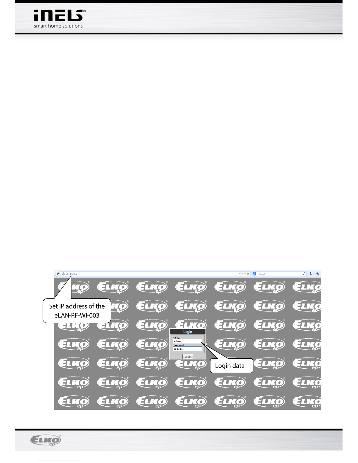
• If you don‘t have a fixed IP address, the Smart RF box will obtain it from DHCP server automatically.
• Power is supplied to the Smart RF box via adapter 10-27V DC (included in the supply) or PoE by
power source (router) 24V DC.
• By connecting two Smart RF boxes by LAN cable, you avoid the problem of lack of signal range.
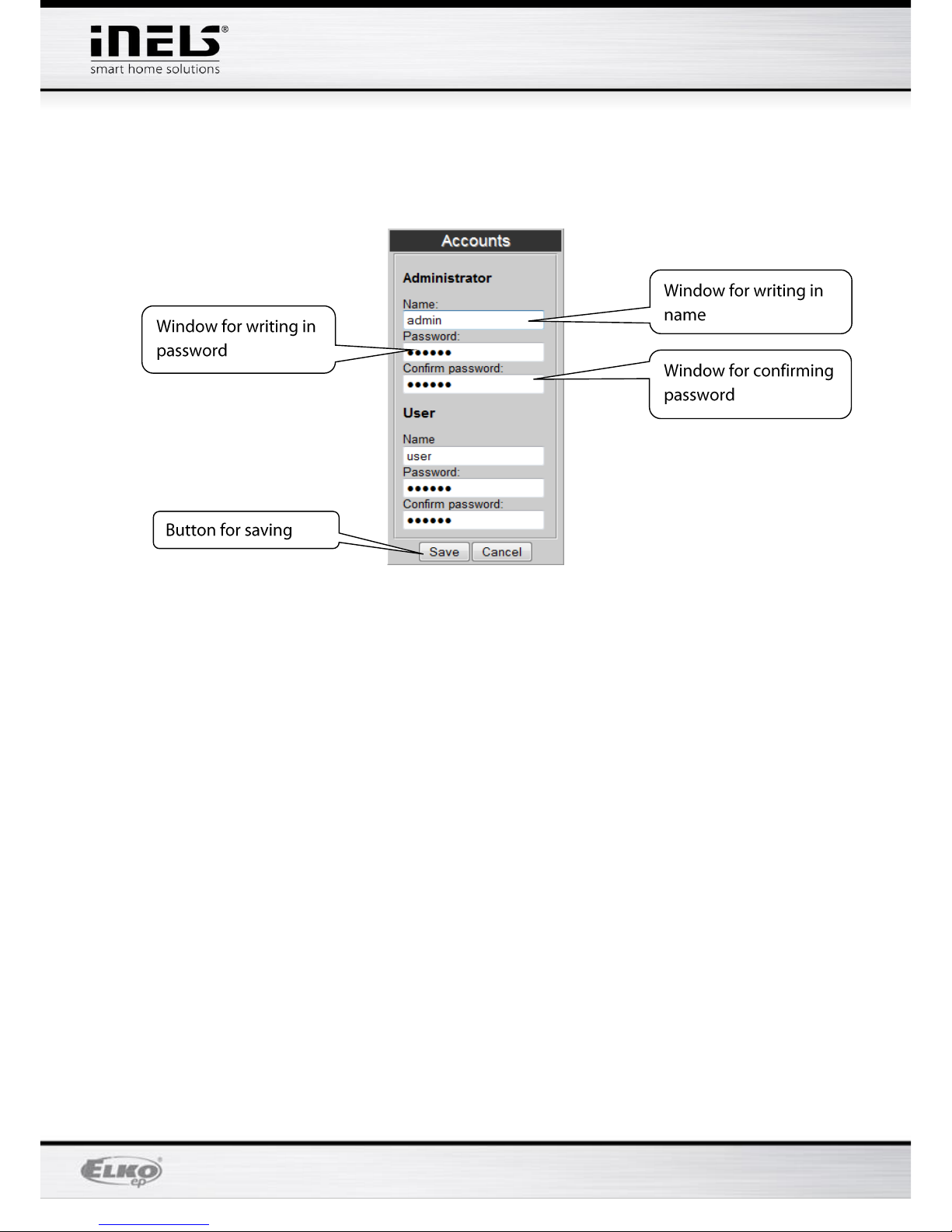
• Option of setting via web interface or directly in the application iHC-MARF (Android) / iHC-MIRF
(iPhone).
• The package includes an internal antenna AN-I, in case the Smart RF box is located in a metal
switchboard, you can use the external antenna AN-E for better signal reception.*
• Range up to 100 m (in open space), if the signal is insufficient between the Smart RF box and unit,
use the signal repeater RFRP-20.
• Communication frequency with bidirectional protocol iNELS RF Control.
* Max Tightening Torque for antenna connector is 0.56 Nm.
Attention:
The minimum distance between the controller (system unit) and the actuator must not be less than
one centimeter.

Page 4of 15
eLAN-RF-Wi-003
Webové rozhraní / rev.3
Setting options:
•max. number of actuator - 40
•max. number of temperature zones - 16
•max. number of time schedules - 16
•max. number of central sources - 10
•max. number of heating and cooling devices in a heating zone - 10
•max. number of intervals in a time schedule - 8
2. Logging in to the web interface eLAN-RF-Wi-003
After connecting the eLAN-RF-Wi-003 to the power source, after around 1 minute
you will see displayed in the list of available WiFi networks the name: ELAN-RF-
WI
Connect to the network by entering the password: 00000000
Write into the panel Address (in the Internet browser) the set IP address of the
product eLAN-RF-Wi-003. (Upon the first configuration, enter the factory-assigned
default IP address: 192.168.1.1)
After confirming the entered IP address, the web server's login page will come up.
The factory settings for signing in as administrator are:
Login: admin
Password: elkoep

Page 5of 15
eLAN-RF-Wi-003
Webové rozhraní / rev.3
Login options:
It is possible to log into the eLAN-RF-Wi-003 web interface either as the
administrator (admin) with full access to controls and settings, or as the user (user),
for whom only the panel itself is displayed.
The user thus only has the option of controlling the device (the factory setting of the
password for logging in as admin and user is: elkoep)
Both users log into the same dialog field (Login, Password), but each uses his/her
own name and password.
Confirm the log in by pressing: Login.
Note: Perform RESET of the eLAN-RF-Wi-003 by a long press of the button on the front panel of the
device until the yellow LED begins flashing. eLAN is restarted at the moment the LED stops flashing.
The IP address and login data return to factory settings.
3. Settings
After logging in, you will see a large window used to display assigned RF-elements
(actuators). On the right you will see a configuration panel with all functions of the web
server eLAN-RF-Wi-003.

Page 6of 15
eLAN-RF-Wi-003
Webové rozhraní / rev.3
Description of configuration panel

Page 7of 15
eLAN-RF-Wi-003
Webové rozhraní / rev.3
Description of functions
By pressing the button Accounts, you will display a window for changing login data.
By pressing Log out, you will log out of the web interface eLAN-RF-Wi-003.
By pressing the button Save settings, you can save the current settings of your eLAN-
RF-Wi-003 including network settings.
By pressing the button Load settings, you can restore your stored settings, which
you have already stored in your PC (the file has the extension .bin).
The button Settings is to configure network settings that you can change any time
based on your network.
If you leave DHCP ON selected by default, the eLAN-RF-Wi-003 always assigns you an
IP address in the range set by default (192.168.1.x).
The IP address of eLAN-RF-Wi-003 can be changed, but in the same range.
If you have your own home Wi-Fi network, switch off the DHCP server by assigning
DHCP OFF and set the IP of the eLAN-RF in the same subnet mask as you have at
home. Set the default gateway the same as your network. Press Save to store the
settings. If you can connect the eLAN-RF-Wi-003 by ethernet cable into your home
network.

Page 8of 15
eLAN-RF-Wi-003
Webové rozhraní / rev.3
Note: If you change the IP address, to log into the eLAN-RF-Wi-003 you must use the new IP
address. If the new IP address that you entered is not in the same subnetwork, the
connection will not work if settings are not changed in the connected device (PC, iMM
Client) to the same subnetwork.
The button RF mode is used to switch the mode of your eLAN-RF-Wi-003.

Page 9of 15
eLAN-RF-Wi-003
Webové rozhraní / rev.3
Repeater
The Repeater function is an independent function of eLAN-RF-Wi-003 and is used to increase
range between RF controllers (system elements) and RF elements.
Use: an eLAN-RF-Wi-003 device configured for a repeater can only be connected to the
supply voltage, and it will then function just the same as the RFRP-20. This means if it
receives a command from the RF controller or RF detector, it resends it to a designated RF
element and vice-versa.
Oasis Compatible
Enables the repeater function to serve unidirectionally communicating units (RF Key, RFWB,
RFIM, detectors, etc.).
RF Touch compatible
Enables the repeater function to serve bidirectionally communicating units (RF Touch, RF
Pilot, etc.).
List of addresses
Repeated address settings - write into the list of addresses those elements with which you
want the eLAN RF. If you set the eLANs to the router mode, the same addresses must be set
for both eLANs…
After setting the function Repeater, eLAN restarts.
Router
The Router function is used to extend the distance and control of RF elements by connecting
two eLANs into the LAN network.
The first eLAN (so-called Master ) must be set during configuration in the Router
function, it receives all RF commands of controllers via an RF signal. It assess the
limitations and permissions of addresses.
The second eLAN (so-called Slave) assess all commands from the eLAN Master
determined for sending by RF signal. It sends valid messages by RF signal to
controlled elements. If a response comes from an element, it sends it to the eLAN
Master.

Page 10 of 15
eLAN-RF-Wi-003
Webové rozhraní / rev.3
It is necessary to enter into the settings the LAN parameters of the second eLAN - Slave (IP
address, login data).
The second eLAN Slave can be configured in two ways.
Active function Repeater – this receives commands via the Ethernet network and via
the RF network.
Example: eLAN Slave catches the RF signal of the RF controller, saves it as Repeater
(signal repeater), and sends the RF signal further along.
Active function Router – eLAN is in its basic setting. eLAN only receives commands
from the Ethernet network, and ignores all RF signals.
Oasis Compatible
The sames as with the Repeater function.
RF Touch Compatible
The sames as with the Repeater function.
List of addresses
The sames as with the Repeater function. The same addresses must be set for both eLANs.
After setting the function Router, eLAN restarts.
Button Date & Time
Here the IP address of the NTP server is set by default, which determines for the eLAN
the precise time via the Internet. You can also set the time zone in which the eLAN is
located. By selecting Daylight Saving Time, you can manually set the daylight saving
time.
Time of eLAN-RF-Wi-003 is automatically set from NTP server.
If your eLAN-RF-Wi-003 is not connected to internet network, then time is always set to
12:00 AM, the current day is set manually with button Manual.
During power failure, time information is erased from eLAN memory.

Page 11 of 15
eLAN-RF-Wi-003
Webové rozhraní / rev.3
The button Update firmware is used to update the firmware (FW).
When updating the eLAN-RF-Wi-003, proceed according to the following instructions:
1 Download the latest firmware version from the website: http://www.elkoep.cz/ke-
stazeni/software/inels-rf-control/
2 Click on the button Update firmware, select the downloaded file (the update file must
always include the extension *.bin ), and click on it. After confirming by pressing OK, the
update of your firmware in your eLAN-RF-Wi-003 automatically starts.
Note: do not turn off device or use the Reset button when updating the firmware. the eLAN-
RF-Wi-003 restarts after updating. After the firmware update, all settings will remain
preserved. This means that the set IP, login data, visualization panel will remain the same as
with the SW version prior to the update.
Button Reboot –to restart the device eLAN-RF-Wi-003.
Panel Rooms displays created rooms.
By pressing the button (+), you can add a new room:
1. ID *of the room "optional data", if you do not enter it - a number is automatically
generated. Here you can only use the characters [0-9A-Za-z_-].
2. Label gives an arbitrary name to the room (you can use diacritical marks, gaps and
others...)

Page 12 of 15
eLAN-RF-Wi-003
Webové rozhraní / rev.3
3. Type –here you select the type of room or type of icon that you will then display
after entering the floorplan on the desktop.
4. Floorplan –here select the floorplan (image) that you added before in the tab
Floorplans.
By pressing (–)you can delete any selected room.
By pressing (X) you can remove all added rooms.
Panel Scenes –Here any scenes are created based on user requirements.
It is possible to create scenes only after you add rooms and actuators.
Button (+) - add a new scene:
1. ID* - name of room (not required).
2. Label - enter any name of the scene (you can use diacritical marks and spaces in
between…).
1. Actions - (+) –add an RF element, (–) delete the selected element, (X) –delete all
RF elements.
When adding an actuator, its function-action is set (switching, dimming, etc.).

Page 13 of 15
eLAN-RF-Wi-003
Webové rozhraní / rev.3
If for an actuator, you select the function ON, you must still confirm this function by its
precise status in the table Choose value, e.g. true –for switching on or false –switching off.
After adding all actuators and their required functions, click on Create, thereby saving the
entire scene.
The panel Devices is used for adding RF actuators to the eLAN-RF-Wi-003.
Button (+) - add a new RF element:
1. Product Type –select RF element
2. Address –enter the address of the RF element that is listed right on the box of
the added EF element (six-character code).
3. Window ID* - name of element (not required).
4. Label - any naming of the element, e.g. "Kitchen light".
5. Type - select the type of icon (e.g. light), which will be displayed on the floorplan.
Create, you will store the RF actuator in the eLAN-RF-Wi-003.

Page 14 of 15
eLAN-RF-Wi-003
Webové rozhraní / rev.3
Button (–) - deleting the selected element.
Button (X) - remove all elements
Panel Floorplans here you can add floorplans (images, layouts….).
Button (+) - add a new floorplan:
1. Select the required image for the floorplan (stored in your PC).
2. ID –enter the name of the floorplan. Confirm by pressing OK.
The number of floorplans is limited by the memory size of the eLAN-RF-Wi-003.
Find out the memory status in the top of the configuration panel.
The panel Device Types - do not adjust or delete anything - only for the needs of
R&D.
The panel Room Types - do not adjust or delete anything - only for the needs of
R&D.
The panel Action - displays options for control of the currently highlighted RF
actuator on the floorplan.

Page 15 of 15
eLAN-RF-Wi-003
Webové rozhraní / rev.3
Adding RF actuators to the floorplan
Click on the room in the Rooms Types panel into which you want to add the required RF
actuator, and a floorplan will then appear on the desktop (not necessary however - a white
space may remain as the floorplan), double-click anywhere on the desktop, and the addition
of RF actors will be activated by a red boundary, and the Devices panel will open. Then
double-click on individual RF actuators to add the RF actuators that you require on the
floorplan.
You have the option of removing the actuator by right-clicking the mouse.
If you do not use any of your added floorplans, you cannot move the icons; if you have an
assigned floorplan in the room, you can move the icons anywhere using the mouse and
distribute them on the floorplan.
Once you add everything, the same as at the start, double-click anywhere on the desktop
(floorplan) to save all you've done.
Controlling RF units
And now after clicking on one of the icons, you can control the RF actuators.
You can do this either by double-clicking directly on them.
Or after a single click on them the offer Action appears in the lower right corner, in which
you double-click to start the required action of the given RF actuator.
Between the individual commands must be an interval of at least 1s.
Starting up scenes
Startup is performed in a similar manner, where after clicking on the panel Scenes, you
select the required scene and then double click on it.
Table of contents
Other iNels Control Unit manuals

iNels
iNels EST3 User manual

iNels
iNels RFSAI-161B User manual

iNels
iNels IM2-80B User manual

iNels
iNels CU3-01M User manual

iNels
iNels EST-2 Series Simple manual

iNels
iNels IM2-80B User manual

iNels
iNels RFATV-2 User manual

iNels
iNels RF KEY-40/W User manual

iNels
iNels RFATV-1 User manual

iNels
iNels CU3-01M User manual
Popular Control Unit manuals by other brands

CKD
CKD QEL Series instruction manual

Signature Hardware
Signature Hardware RYLE 934425 quick start guide

Allen-Bradley
Allen-Bradley DeviceNet 1747-SDN/B installation instructions

Grundfos
Grundfos CIM 260 instructions

Crow
Crow 4 OUTPUTS RELAY EXPANDER BOARD OUTPUT MODULE... Installation instruction

Edwards
Edwards Speedivalve SP5 instruction manual