manuals.online logo
Brands
  1. Home
  2. •
  3. Brands
  4. •
  5. iNels
  6. •
  7. Control Unit
  8. •
  9. iNels CU3-01M User manual

iNels CU3-01M User manual

CU3-01M, CU3-02M
1/3
1
4
5
6
2
3
7
8
12
14
13
11
10
9
EN Central unit
Characteristics
- CU3-01M and CU3-02M are central units’ of the iNELS system and mediators, between user software interface and controllers, units and actuators connected to the BUS.
- It‘s possible to directly connect up to 2 lines of BUSes in to CU3-01M and CU3-02M, and on each BUS we can connect up to 32 iNELS3 units.
- The main difference between CU3-02M and CU3-01M is that CU3-02M is moreover equipped by RF module which enables communication with selected units from iNELS RF Control system.
- Central units CU-01M (02M) support also peripheral units from iNELS2 thanks to external master MI3-02M/iNELS2.
- User´s project and retentive data are stored in a non-volatile internal memory hereby data are backed up without the supply voltage. Real time clock (RTC) backup for 10 days.
- Power supply controlling system - network voltage and the status of the backup battery.
- Possibility of setting time synchronization via NTP server.
- The RJ45 Ethernet port‘s connector is located on the front panel of the unit, the transmission speed is 100 Mbps.
- For CU3-01M (02M) it is possible to use 4 potential-free inputs for connecting external controllers (buttons, switches, sensors, detectors, etc.) and 2 analog inputs 0 - 30V.
- CU3-01M (02M) comes with OLED display that shows the current status and enables settings (network settings, date, time, service) of the central unit CU3-01M (02M).
- Movement in the menu CU3-01M (02M) using arrows on the front panel.
- CU3-01M (02M) in 6-MODULE are designed for mounting into a switchboard on the EN60715 DIN rail.
Installation BUS:
-
Two-wired BUS with an arbitrary topology (not only to be as closed circle).
-
With its own modulated communications on the DC voltage supply.
-
One line of BUS allows you to connect up max. 32 units of iNELS3, or iNELS2 if you use external master MI3-02M/iNELS2.
-
The current load of one line is max. 1A.
- M
aximum length of the BUS is approximately 550 m (depends on the voltage drop).
-
Recommended cable:
- iNELS BUS Cable - Twisted pair of copper wires with size of AWG20 wire (diameter of 0.812 mm, cross-section of 0.5190 mm
2
).
System BUS EBM:
-
Used to connect the CU3-01M(02M) central unit with MI3-02M external masters, MI3-02M/iNELS2, GSM communicator GSM3-01M or converter DALI/DMX EMDC-64M.
-
EBM has strictly linear topology and wires are connected to terminals EBM + and EBM-, wires can not be interchanged.
-
Max. length of the line of BUS is 500 m.
-
The EBM BUS has to be terminated at both ends.
-
This part adapted to be inserted between terminals is included into central units packages and it is necessary to insert between terminals EBM+ and EBM-.
-
Reccomended cabling:
- CAT5e UTP and higher, or FTP CAT5e and higher or STP CAT5e and higher.
-
The configurations of units and the whole system are done via Ethernet, through configuration software - iNELS3 Designer & Manager (iDM3), which is designed for operating systems Windows 7, Windows
8 and Windows 10.
-
The central unit features two communication protocols:
- ELKONET - to communicate with iMM and Connection Server or directly with the application iHC.
- ASCII - communication with third systems and integration with BMS (Building Management Systems), for example Niagara 4.
-
Supported Software:
- Parameterization, configuration, control and visualization:
iNELS3 Designer & Manager (iDM3).
-
By means of iDM3, you can update firmware of central units and peripheral units connected by BUS.
Description of device
1. Data BUS1
2. Supply voltage terminals
3. LED indication Ethernet speed 100 Mbps
4. LED indication for Ethernet communication
5. Ethernet port 100 Mbps (RJ45)
6. Analog inputs 0-30 V DC
7. Data BUS2
8. System BUS EBM
9. SMA antenna connector (CU3-02M)
10. Operational state of unit LED indication
11. Information display
12. Routing buttons
13. Relay output NO/GND
14. Digital inputs
CU3-01M, CU3-02M
CU3-02M
2/3
ashing - communication with BUS; ON - no communication
ashing - no project, ON - unit STOP
displays the current status and settings
color OLED
128x128 / 1:1 aspect ratio
26 x 26 mm
using arrows
accuracy: 1s/day at 23 °C
4x NO or NC to GND (-) / 2 analogue inputs 0 ÷ 30 V
relay output- NO/GND
max. 64 (2x32)
up to 576 units (CU3-01M (02M) and 8x MI3-02M)
max. 32 units to one BUS line
max. 550 m (depends on power loss)
max. 500 m
up to 8 (regards to increasing the cycle turns)
RJ45 on the front panel
100 Mbps
green - Ethernet communication / yellow - Ethernet speed 100 Mbps
192.168.1.1 (the IP address can be changed in the menu using the display and buttons)
27 V DC, -20 / +10 %
110 mA (at 27V DC)
-20 to +55 °C
-25 to +70 °C
max. 80 %
IP 20 devices, IP 40 with cover in the switchboard
II.
2
any
to the switching board on the EN60715 DIN rail
6-MODULE
max. 2.5 mm2
90 x 105 x 65 mm
250 g
RF Touch Compatible
868 MHz / 915 MHz / 916 MHz
bidirectionally addressed message
SMA connector *
1 dB (part of package)
up to 100 m
Technical parameters
LED indication
Green LED RUN:
Red LED ERR:
OLED display
Type:
Resolution:
Visible area:
Controlling:
The internal real-time clock:
Inputs
Inputs:
Outputs
Output:
Number of connected units (directly to the
CU3-01M (02M):
Expansion possibilities external BUS master:
Communication
BUS
Maximum number of units:
Maximum cable length:
System BUS EBM
Maximum cable length:
Number of connected ext.masters:
Ethernet
Connector:
Communication speed:
Indication of the Ethernet:
The default IP address:
Supply
Supply voltage / tolerance:
Rated current:
Operating conditions
Working temperature:
Storage temperature:
Humidity:
Degree of protection:
Overvoltage category:
Degree of pollution:
Operating position:
Installation:
Design:
Terminal:
Dimensions:
Weights:
iNELS RF Control interface
Communication protocol:
Transmitting frequency:
Signal transmission methods:
Output for RF antenna:
RF antenna:
Free space range:
* Max Tightening Torque for antenna connector is 0.56 Nm.
02-72/2017
Rev.0
3/3
+-
+
-
BUS
1+
BUS
1-
B
US
2
+
B
US
2
-
MA
C:
xx
:
xx
:
xx
:
xx
:
xx
:
xx
iNEL
S:
xxxxx
x
BUS
2 B
US
1
BUS
2+ B
US
2
-
B
US
1+ B
US
1
-
+
-
+
-
BUS1
BUS2
12V EZS
ELKO EP, s.r.o. | Palackého 493 | 769 01 Holešov, Všetuly | Czech republic | e-mail: [email protected]
TECHNICAL SUPPORT | E-mail: [email protected] | Mobil: +420 778 427 366 | Tel.: +420 573 514 276, +420 573 514 211 | Fax: +420 573 514 227 | www.inels.com
Warning
Before the device is installed and operated, read this instruction manual carefully and with full understanding and Installation Guide System iNELS3. The instruction manual is designated for mounting the
device and for the user of such device. It has to be attached to electro-installation documentation. The instruction manual can be also found on a web site www.inels.com. Attention, danger of injury by
electrical current! Mounting and connection can be done only by a professional with an adequate electrical qualification, and all has to be done while observing valid regulations. Do not touch parts of
the device that are energized. Danger of life-threat! While mounting, servicing, executing any changes, and repairing it is essential to observe safety regulations, norms, directives and special regulations
for working with electrical equipment. Before you start working with the device, it is essential to have all wires, connected parts, and terminals de-energized. This instruction manual contains only general
directions which need to be applied in a particular installation. In the course of inspections and maintenance, always check (while de-energized) if terminals are tightened.
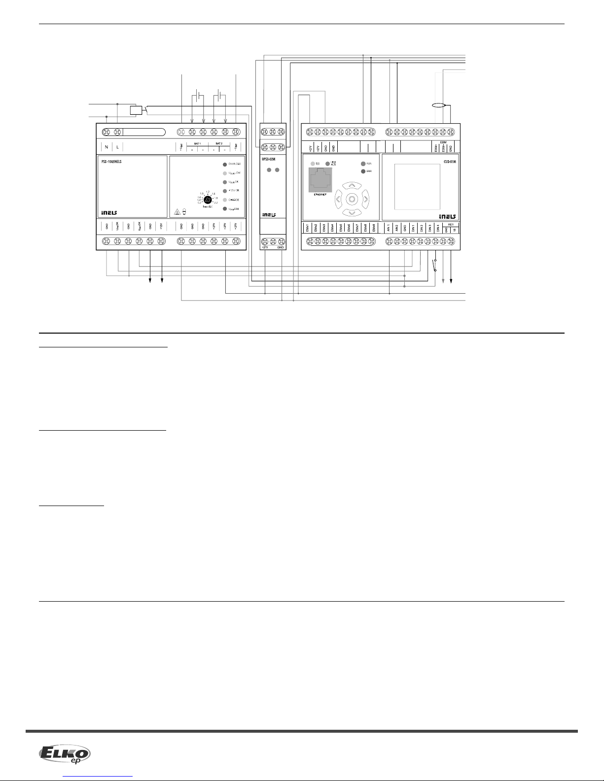
Connection
maximum of 32 units per line BUS; maximum 1A per line BUS
EBM to MI3-02M, MI3-02M/iNELS2,
GSM3-01M or EMDC-64M
Auxiliary relay coil 230V AC/5 mA
switching contact e.g. VS116K
24 V battery
battery 1
12 V
battery 2
12 V
General instrucions
CONNECTION TO THE SYSTEM, INSTALLATION BUS
iNELS3 peripheral units are connected to the system through the BUS installation. Installation BUS conductors are connected to the terminal units to BUS + and BUS-terminals, wires cannot be
interchanged. For installation of BUS it is necessary to use a cable with a twisted pair of wires with a diameter of at least 0.8 mm, the recommended cable is iNELS BUS Cable, whose features best meet the
requirements of the BUS installation. Bearing in mind that in terms of all the properties iit is it is possible in most cases also use the cable JYSTY 1x2x0.8 or JYSTY 2x2x0.8, however it is not recommended
as the best option. In the case of a cable with two pairs of twisted wires it is not possible to use the second pair of the other for modulated signal due to the speed of communications; it is not possible
within one cable to use one pair for one segment BUS and the second pair for the second segment BUS. For installation of BUS it is vital to ensure that it is kept at a distance from the power lines of at least
30 cm and must be installed in accordance with its mechanical proper ties. To increase mechanical resistance of cables we recommend installation into a conduit of suitable diameter. Topology installation
of BUS is free except for a circle, each end of the BUS must terminate at terminals BUS+ and BUS-. While maintaining all the above requirements, the maximum length of one segment of the installation
BUS can reach up to 550 m. Due to the data communication and supply of units in one pair of wires, it is necessary to keep in mind the diameter of wires with regards to voltage loss on the lead and the
maximum current drawn. The maximum length of the BUS applies provided that they comply with the tolerance of the supply voltage.
CONNECTION TO THE SYSTEM, BUS SYSTEM EBM
System units MI3-02M, MI3-02M/iNELS2, EMDC-64M and GSM3-01M connect to the system through the EBM BUS system. The BUS system conductors are connected to the terminals EBM+ and EBM-,
wires can not be interchanged. The BUS system EBM is essentially a symmetrical high-speed RS485 interface and, as such, subject to requirements of the appropriate conduit. When installing the EBM
BUS system it is necessary to observe all the requirements for the installation of the RS485 interface. It is particularly important to avoid overlapping with power lines (maintain a distance of at least 30 cm)
and pay attention to equipment generating emissions when these are located in the vicinity of system units or the EBM BUS management system. These emissions must be suppressed to a desired level.
For the EBM BUS system it is necessary to use CAT5e UTP cable or higher, or an FTP CAT5e and higher STP CAT5e or higher. For the EBM BUS management system it is not possible to use JYSTY cable or
iNELS BUS Cable, which are used to guide the installation of BUS. EBM system BUS topology is strictly linear and there are no branches on the BUS. Both ends of the EMB BUS system require to terminate
by using a resistor with a nominal value of 120Ω resistance. Units CU3-01M, CU3-02M, MI3-02M, MI3-02M/iNELS2 and GSM3-01M this resistor is inserted between the terminals and EBM+ EBM-. The unit
EMDC-64M resistor is included with the unit and closing is done by shorting adjacent terminals TERM and EBM+.
SUPPLYING THE SYSTEM
For supplying power to system units, it is possible to use the power sources of ELKO EP titled PS3-100/iNELS. We recommend backing up the system with backup batteries connected to the source of PS3-100/iNELS
(see sample diagram of connecting the control system).
Installation Manual CU3-0xM central unit, installation manual iNELS and configuration software iDM3 are available for download on the website www.inels.cz section for system partners.
To obtain credentials, please contact us at the email address info@inels.cz.

Other manuals for CU3-01M

2

This manual suits for next models

1

Other iNels Control Unit manuals

iNels EST-2 Series Simple manual

iNels

iNels EST-2 Series Simple manual

iNels CU3-01M User manual

iNels

iNels CU3-01M User manual

iNels EST3 User manual

iNels

iNels EST3 User manual

iNels RF KEY-40/W User manual

iNels

iNels RF KEY-40/W User manual

iNels RF KEY-40/W User manual

iNels

iNels RF KEY-40/W User manual

iNels RFATV-2 User manual

iNels

iNels RFATV-2 User manual

iNels eLAN-RF-Wi-003 User manual

iNels

iNels eLAN-RF-Wi-003 User manual

iNels IM2-80B User manual

iNels

iNels IM2-80B User manual

iNels RFSAI-161B User manual

iNels

iNels RFSAI-161B User manual

iNels IM2-80B User manual

iNels

iNels IM2-80B User manual

iNels RFATV-1 User manual

iNels

iNels RFATV-1 User manual

Popular Control Unit manuals by other brands

Texas Instruments TRF7970A BoosterPack user guide

Texas Instruments

Texas Instruments TRF7970A BoosterPack user guide

HUBER+SUHNER IANOS Standard Module installation manual

HUBER+SUHNER

HUBER+SUHNER IANOS Standard Module installation manual

LS LSUM 086R4C 0093F EA user manual

LS

LS LSUM 086R4C 0093F EA user manual

JUMO mTRON B 70.4015.4 installation instructions

JUMO

JUMO mTRON B 70.4015.4 installation instructions

Rockwell Automation Allen-Bradley MSR42 user manual

Rockwell Automation

Rockwell Automation Allen-Bradley MSR42 user manual

Nibe MODBUS 40 Installer manual

Nibe

Nibe MODBUS 40 Installer manual

SCIENCE LCTA quick start guide

SCIENCE

SCIENCE LCTA quick start guide

SpaNet SV2 Quick reference guide

SpaNet

SpaNet SV2 Quick reference guide

INVT IVC-EH-4DA user manual

INVT

INVT IVC-EH-4DA user manual

Pilz PNOZ m EF 4DI4DOR operating manual

Pilz

Pilz PNOZ m EF 4DI4DOR operating manual

Nittan EVA-ZMU-SCI instruction manual

Nittan

Nittan EVA-ZMU-SCI instruction manual

MKS T3B Series Supplement

MKS

MKS T3B Series Supplement

Lenze 9350 operating instructions

Lenze

Lenze 9350 operating instructions

DIEL ME 100 V3 Installation and instruction manual

DIEL

DIEL ME 100 V3 Installation and instruction manual

Geco G-403-P02 user manual

Geco

Geco G-403-P02 user manual

WinSystems PCM-AIO Operation manual

WinSystems

WinSystems PCM-AIO Operation manual

Siemens LMV36.520A1 Basic documentation

Siemens

Siemens LMV36.520A1 Basic documentation

Emerson CSI 6500 quick start guide

Emerson

Emerson CSI 6500 quick start guide

manuals.online logo
manuals.online logoBrands
  • About & Mission
  • Contact us
  • Privacy Policy
  • Terms and Conditions

Copyright 2025 Manuals.Online. All Rights Reserved.