Inficon MPG400 User manual

Operating Manual
tina48e1-c (2017-10) 1
Inverted Magnetron Pirani Gauge
MPG400
MPG401

2tina48e1-c (2017-10) MPG400-401.om
In all communications with INFICON, please specify the information given on the
product nameplate. For convenient reference copy that information into the space
provided below:
This document applies to products with part number:
MPG400 (FPM sealed) MPG401 (all-metal)
351-010 (DN 25 ISO-KF) 351-020 (DN 25 ISO-KF)
351-011 (DN 40 ISO-KF) 351-021 (DN 40 ISO-KF)
351-012 (DN 40 CF-C) 351-022 (DN 40 CF-C)
The part number (PN) can be taken from the product nameplate.
If not indicated otherwise in the legends, the illustrations in this document
correspond to the product with part number 351-010. They apply to the other
products by analogy.
We reserve the right to make technical changes without prior notice.
All dimensions in mm.
The Inverted Magnetron Pirani Gauges MPG400 und MPG401 has been designed
for vacuum measurement in the pressure range of 5×10⁻⁹ … 1000 mbar.
The Inverted Magnetron Pirani Gauges must not be used for measuring flammable
or combustible gases which react in air.
The gauges can be used with an INFICON Controller of the VGC40x / VGC50x
series or with another evaluation unit.
Over the whole measuring range, the measuring signal is output as a logarithm of
the pressure.
The gauge consists of two separate measuring systems (the Pirani and the cold
cathode system according to the inverted magnetron principle). They are combined
in such a way that for the user, they behave like one measuring system
Product Identification
Validity
Intended Use
Functional Principle

tina48e1-c (2017-10) MPG400-401.om 3
Contents
Product Identification 2
Validity 2
Intended Use 2
Functional Principle 2
1Safety 4
1.1 Symbols Used 4
1.2 Personnel Qualifications 4
1.3 General Safety Instructions 4
1.4 Liability and Warranty 5
2Technical Data 6
3Installation 9
3.1 Vacuum Connection 9
3.1.1 Removing the Magnet Unit (Only for Gauges With CF Flanges) 11
3.2 Electrical Connection 12
3.2.1 Use With an INFICON Controller 12
3.2.2 Use With Another Control Device 12
4Operation 13
4.1 Measurement Principle, Measuring Behavior 13
5Deinstallation 15
6Maintenance 16
6.1 Adjusting the Gauge 16
6.2 Cleaning MPG400, Replacing Parts 18
6.2.1 Disassembling MPG400 18
6.2.2 Cleaning MPG400 19
6.2.3 Reassembling MPG400 20
6.3 Cleaning MPG401, Replacing Parts 21
6.3.1 Disassembling MPG401 22
6.3.2 Cleaning MPG401 23
6.3.3 Reassembling MPG401 24
6.4 Troubleshooting 25
7Accessories 26
8Spare Parts 26
9Returning the Product 28
10 Disposal 28
Appendix 29
A: Measuring Signal vs. Pressure 29
B: Gas Type Dependence 30
ETL Certification 31
For cross-references within this document, the symbol (→XY) is used.

4tina48e1-c (2017-10) MPG400-401.om
1 Safety
DANGER
Information on preventing any kind of physical injury.
WARNING
Information on preventing extensive equipment and environmental damage.
Caution
Information on correct handling or use. Disregard can lead to malfunctions or
minor equipment damage.
Skilled personnel
All work described in this document may only be carried out by persons who
have suitable technical training and the necessary experience or who have been
instructed by the end-user of the product.
•Adhere to the applicable regulations and take the necessary precautions for the
process media used.
Consider possible reactions between the materials (→7) and the process
media.
Consider possible reactions (e.g. explosion) of the process media due to the
heat generated by the product.
•Adhere to the applicable regulations and take the necessary precautions for all
work you are going to do and consider the safety instructions in this document.
•Before beginning to work, find out whether any vacuum components are con-
taminated. Adhere to the relevant regulations and take the necessary precau-
tions when handling contaminated parts.
DANGER
DANGER: magnetic fields
Strong magnetic fields can disturb electronic devices like heart
pacemakers or impair their function.
Maintain a safety distance of ≥10 cm between the magnet and the
heart pacemaker or prevent the influence of strong magnetic fields by
antimagnetic shielding.
Communicate the safety instructions to all other users.
1.1 Symbols Used
1.2 Personnel Qualifications
1.3 General Safety
Instructions

tina48e1-c (2017-10) MPG400-401.om 5
INFICON assumes no liability and the warranty becomes null and void if the end-
user or third parties
•disregard the information in this document
•use the product in a non-conforming manner
•make any kind of interventions (modifications, alterations etc.) on the product
•use the product with accessories not listed in the corresponding product
documentation.
The end-user assumes the responsibility in conjunction with the process media
used.
Gauge failures due to contamination, as well as expendable parts (filament), are
not covered by the warranty.
1.4 Liability and Warranty

6tina48e1-c (2017-10) MPG400-401.om
2 Technical Data
Measuring range (air, N2) 5×10⁻⁹ … 1000 mbar
Accuracy (N2) ≈±30%
in the range 1×10⁻⁸ … 100 mbar
Reproducibility ≈±5%
in the range 1×10⁻⁸ … 100 mbar
Gas type dependence →Appendix B
Output signal (measuring signal)
Voltage range 0 … +10.5 V
Measuring range 1.82 … 8.6 V
Voltage vs. pressure logarithmic, 0.6 V / decade
(→Appendix )
Error signal <0.5 V no supply
>9.5 V Pirani measurement element
defective (filament rupture)
Output impedance 2×10 Ω
Minimum loaded impedance 10 kΩ, short-circuit proof
Response time (pressure dependent)
p > 10-6 mbar
p = 10-8 mbar
<10 ms
≈1000 ms
Gauge identification 85 kΩreferenced to supply common
Status Pin 6
p > 10-2 mbar
Pirani-only mode Low = 0 V
p < 10-2 mbar
Cold cathode not ignited
Pirani-only mode
Low = 0 V
p < 10-2 mbar
Cold cathode ignited
Combined Pirani / cold cathode
mode
High = 15 … 30 V (dc)
Lamp High voltage on (LED on)
Supply
DANGER
The gauge may only be connected to power supplies, instruments or
control devices that conform to the requirements of a grounded extra-
low voltage (PELV). The connection to the gauge has to be fused1).
Supply voltage at the gauge 15.0 … 30.0 V (dc) (ripple ≤1 V
pp
)
Power consumption ≤2 W
Fuse1) ≤1 AT
The minimum voltage of the power supply must be increased proportionally to the
length of the sensor cable.
Voltage at the supply unit with
maximum line length
16.0 … 30.0 V (dc) (ripple ≤1 Vpp)
1) INFICON controllers fulfill these requirements.

tina48e1-c (2017-10) MPG400-401.om 7
Adjustment
<HV> potentiometer at <10-4 mbar
<ATM> potentiometer at atmospheric pressure
Electrical connection FCC68 female, 8 poles
Sensor cable 8 conductors plus shielding
Line length ≤50 m (8×0.14 mm²)
Operating voltage ≤3.3 kV
Operating current ≤500 µA
Grounding concept →("Electrical Connection")
Vacuum connection-signal common connected via 10 kΩ
(max. voltage differential
with respect to safety ±50 V
with respect to accuracy ±10 V)
Supply common-signal common conducted separately
Materials exposed to vacuum
Vacuum connection
Measuring chamber
Feedthrough
Internal seals
MPG400
MPG401
Anode
Ignition aid
Pirani measuring tube
Pirani filament
stainless steel
stainless steel
ceramic
FPM 75
Ag, Cu, soft solder (Sn, Ag)
Mo
stainless steel
Ni, Au
W
Mounting orientation any
Internal volume ≈20 cm³
Pressure ≤10 bar (absolute)
limited to inert gases
Temperatures
Operation
MPG400
MPG401
+5 … +55 °C
+5 … +150 °C
(at flange in horizontal mounting orien-
tation, without magnetic shielding)
Bakeout +150 °C
(without magnetic shielding and
electronics unit)
Pirani filament +120 °C
Storage –40 °C … +65 °C
Relative humidity ≤80% at temperatures up to +31 °C
decreasing to 50% at +40 °C
Use indoors only
altitude up to 2000 m
Degree of protection IP 40

8tina48e1-c (2017-10) MPG400-401.om
Dimensions [mm]
18
DN 25 ISO-KF
18.5
DN 40 ISO-KF
DN 40 CF-F
24
92
ø 63.5
28 55
60
75
MPG400
105
32 55
60
75
15.5
ø 63.5
MPG401
Weight
351-010 ≈700 g
351-011 ≈720 g
351-012 ≈980 g
351-020 ≈730 g
351-021 ≈750 g
351-022 ≈1010 g

tina48e1-c (2017-10) MPG400-401.om 9
3 Installation
DANGER
DANGER: overpressure in the vacuum system >1 bar
Injury caused by released parts and harm caused by escaping process
gases can result if clamps are opened while the vacuum system is
pressurized.
Do not open any clamps while the vacuum system is pressurized. Use
the type of clamps which are suited to overpressure.
DANGER
DANGER: overpressure in the vacuum system >2.5 bar
KF flange connections with elastomer seals (e.g. O-rings) cannot
withstand such pressures. Process media can thus leak and possibly
damage your health.
Use O-rings provided with an outer centering ring.
DANGER
DANGER: protective ground
Products that are not professionally connected to ground can be
extremely hazardous in the event of a fault.
The gauge must be electrically connected to the grounded vacuum
chamber. The connection must conform to the requirements of
protective connection according to EN 61010:
•CF connections fulfill this requirement.
•For gauges with KF connections, use a conductive metallic clam-
ping ring.
Caution
Caution: vacuum component
Dirt and damages impair the function of the vacuum component.
When handling vacuum components, take appropriate measures to
ensure cleanliness and prevent damages.
Caution
Caution: dirt sensitive area
Touching the product or parts thereof with bare hands increases the
desorption rate.
Always wear clean, lint-free gloves and use clean tools when working
in this area.
WARNING
WARNING: electric arcing
Helium may cause electric arcing with detrimental effects on the
electronics of the product.
Before performing any tightness tests put the product out of operation
and remove the electronics unit.
3.1 Vacuum Connection

10 tina48e1-c (2017-10) MPG400-401.om
The gauge may be mounted in any orientation. To keep condensates
and particles from getting into the measuring chamber preferably
choose a horizontal to upright position and possibly use a seal with a
centering ring and filter.
If adjustment should be possible after the gauge has been installed, be
sure to install it so that the <HV> and <ATM> trimmer potentiometers
can be accessed with a screw driver (→16).
Remove the protective lid and install the product to the vacuum system.
When making a CF flange connection, it may be advantageous to temporarily
remove the magnet unit (→11).
or
Protective lid
Clamp
Seal with centering ring
Seal with centering
ring and filter
Keep the protective lid.
Procedure

tina48e1-c (2017-10) MPG400-401.om 11
•Allen wrench 1.5 mm
•Open-end wrench 7 mm
3
2
4
7
1
a) Unfasten the hexagon socket set screw (1) on the electronics unit (2).
b) Remove the electronics unit without twisting it.
c) Unfasten the hexagon head screw (3) on the magnet unit (4) and remove the
magnet unit.
The magnetic force and the tendency to tilt make it difficult to
separate the magnet unit and the measuring chamber (7).
d) Make the flange connection between the gauge and the vacuum system.
e) Remount the magnet unit and lock it with the hexagon head screw (3).
f) Carefully mount the electronics unit (2). (Make sure the pin of the Pirani ele-
ment is properly plugged into the corresponding hole of the electronics unit.)
g) Push the electronics unit up to the mechanical stop and lock it with the hexagon
socket set screw (1).
3.1.1 Removing the Magnet
Unit (Only for Gauges
With CF Flanges)
Tools required
Procedure

12 tina48e1-c (2017-10) MPG400-401.om
Make sure the vacuum connection is properly made (→9).
Connect the sensor cable to the gauge and the controller.
Make a sensor cable according to the diagram.
Electrical connection
8-pin
FCC-68
connector
Pin 1 Supply (15 … 30 V (dc)
Pin 2 Supply common
Pin 3 Signal output (measuring signal)
Pin 4 Identification
Pin 5 Signal common
Pin 6 Status
Pin 7, 8 n.c.
Connect the sensor cable to the gauge and the controller.
3.2 Electrical Connection
Precondition
3.2.1 Use With an INFICON
Controller
3.2.2 Use With Another Control
Device

tina48e1-c (2017-10) MPG400-401.om 13
4 Operation
As soon as the required supply voltage is applied, the measuring signal is available
between pins 3 and 5. (→Appendix for the relationship between the measuring
signal and the pressure).
Allow for a stabilizing time of approx. 10 min. Once the gauge has been switched
on, permanently leave it on irrespective of the pressure.
The gauge consists of tow separate measuring systems (Pirani and cold cathode
system according to the inverted magnetron principle). They are combined in such
a way that for the user, they behave like one measuring system.
The optimum measuring configuration for the particular pressure range, in which
measurement is performed, is used:
10-4 mbar
10-2 mbar
1000 mbar
5×10⁻⁹ mbar
Cald cathode Pirani
•The Pirani measuring circuit is always on
•The cold cathode measuring circuit is controlled by the Pirani circuit and is
activated only at pressures <1×10⁻² mbar
The identification output (pin 6) indicates the current status of the gauge:
Pressure Lamp on the
gauge
Operating mode Pin 6
p > 1×10⁻² mbar Pirani-only mode Low = 0 V
p < 1×10⁻² mbar
Cold cathode not
ignited
Pirani-only mode
Low = 0 V
p < 1×10⁻² mbar
Cold cathode ignited
Combined Pirani / cold
cathode mode
High = 15 … 30 VDC
As long as the cold cathode measuring circuit has not ignited, the measuring value
of the Pirani is output as measuring signal.
The measuring signal depends on the type of gas being measured. The curves are
accurate for dry air, O2, CO and N2. They can be mathematically converted for
other gases (→Appendix B).
If you are using an INFICON controller, you can enter a calibration factor to correct
the pressure reading (→of that controller).
An ignition delay occurs when cold cathode gauges are switched on. The delay
time increases at low pressures and for clean, degassed gauges it is typically:
10-5 mbar ≈1 second
10-7 mbar ≈20 seconds
5×10⁻⁹ mbar ≈2 minutes
The ignition is a statistical process. Already a small amount of depositions on the
inner surfaces can have a strong influence on it.
4.1 Measurement Principle,
Measuring Behavior
Gas type dependence
Ignition delay

14 tina48e1-c (2017-10) MPG400-401.om
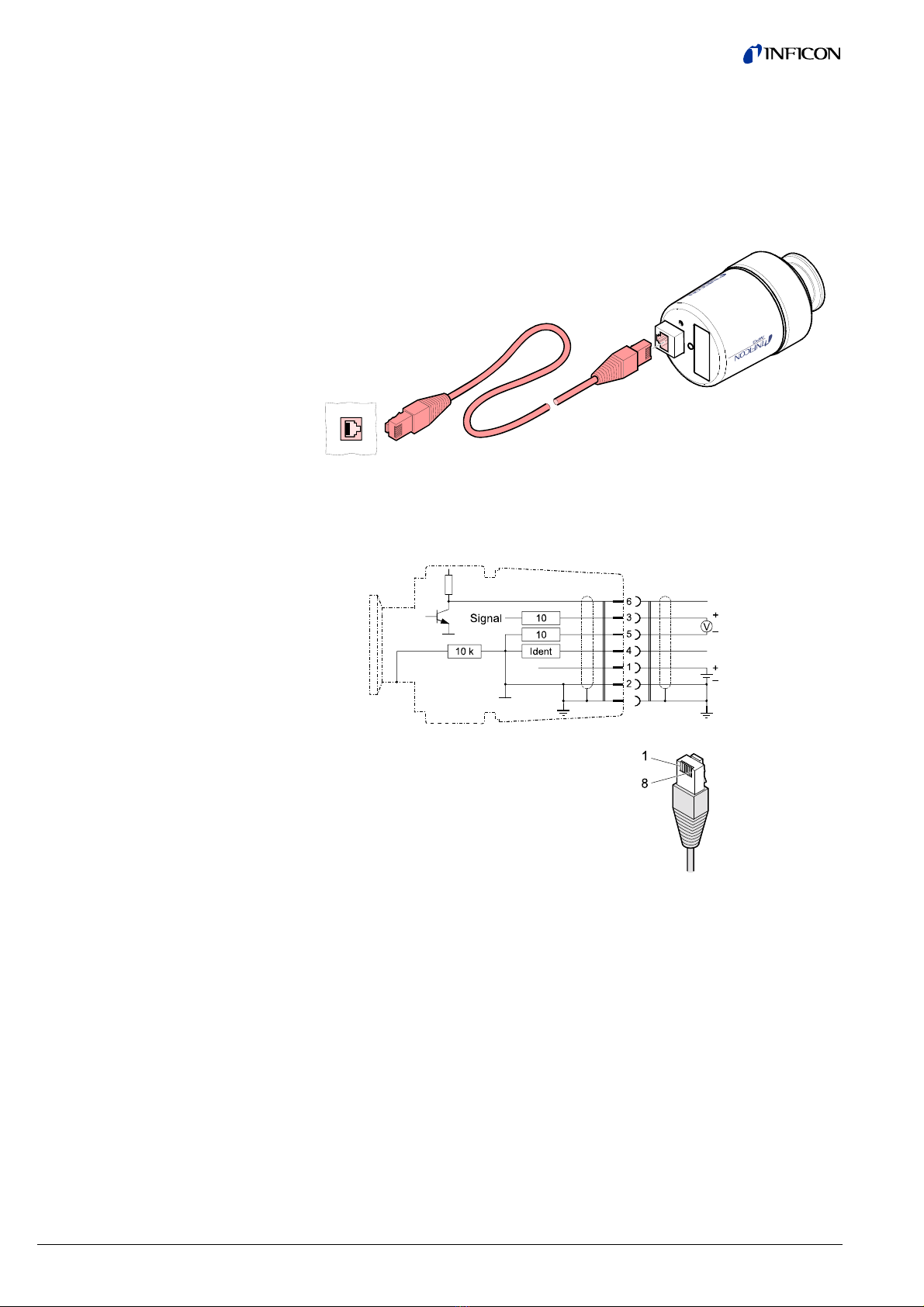
As long as the cold cathode measuring circuit has not yet ignited, the measured
value of the Pirani is output as measuring signal. The identification output (pin 6,
low) indicates the Pirani-only mode.
If the gauge is activated at a pressure p < 3×10⁻⁹, the gauge cannot
recognize whether the cold cathode system has ignited.
Once flanged on, permanently leave the gauge in the operating mode
irrespective of the pressure range. Like this, the ignition delay of the cold
cathode measuring circuit is always negligible (<1 s), and thermal
stabilizing effects are minimized.
Gauge failures due to contamination, as well as expendable parts
(filament), are not covered by the warranty.
Gauge contamination is influenced by the process media used as well as by any
present or new contaminants and their respective partial pressures. Continuous
operation in the range of 10-4 mbar … 10-2 mbar can cause severe contamination
as well as reduced up-time and maintenance cycles. With constantly low pressures
(p <1×10⁻⁶ mbar), the gauge can be operated for more than one year without
cleaning (cleaning the gauge →18, 21).
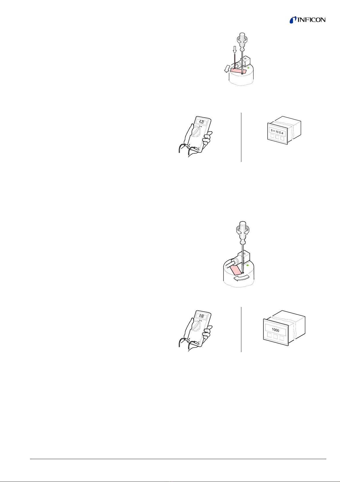
Contamination of the gauge generally causes a deviation of the measured values:
•In the high pressure range (1×10⁻³ mbar … 0.1 mbar), the pressure reading is
too high (contamination of the Pirani element). Readjustment of the Pirani
measuring system →16.
•In the low pressure range (p < 1×10⁻³ mbar), the pressure reading is usually too
low (contamination of the cold cathode system). In case of severe contami-
nation, instabilities can occur (layers of the measuring chamber peel off).
Contamination due to insulation layers can even lead to a complete failure of
the discharge ("Underrange" is displayed).
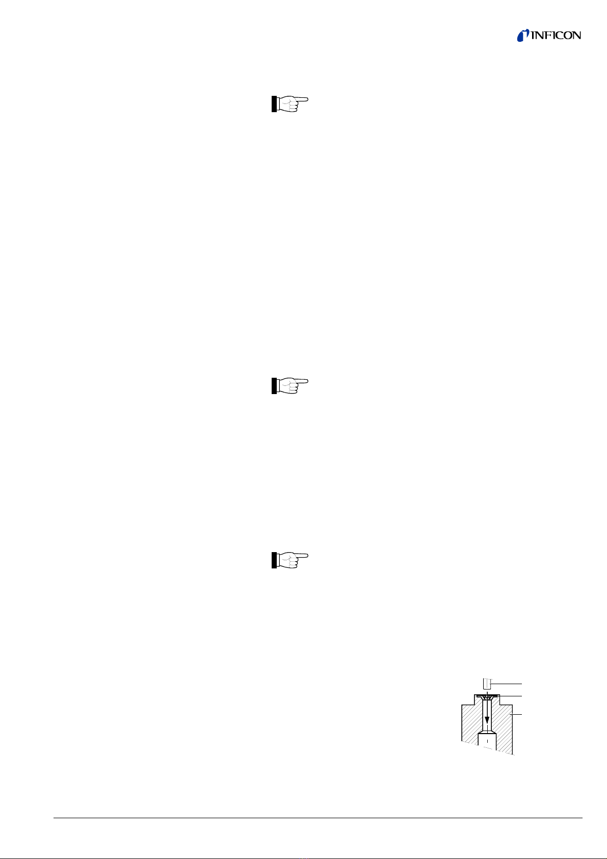
Contamination can to a certain extent be reduced by:
•geometric protection measures (e.g. screenings, elbows) for particles that
spread rectilinearly
•mounting the flange of the gauge at a place where the partial pressure of the
pollutants is particularly low.
Special precautions are required for vapors deposited under plasma (of the cold
cathode measuring system). It may even be necessary to temporarily switch of the
gauge while such vapors occur.
Contamination

tina48e1-c (2017-10) MPG400-401.om 15
5 Deinstallation
DANGER
DANGER: contaminated parts
Contaminated parts can be detrimental to health and environment.
Before beginning to work, find out whether any parts are contami-
nated. Adhere to the relevant regulations and take the necessary
precautions when handling contaminated parts.
Caution
Caution: vacuum component
Dirt and damages impair the function of the vacuum component.
When handling vacuum components, take appropriate measures to
ensure cleanliness and prevent damages.
Caution
Caution: dirt sensitive area
Touching the product or parts thereof with bare hands increases the
desorption rate.
Always wear clean, lint-free gloves and use clean tools when working
in this area.
Vent the vacuum system.
Put the gauge out off operation and unplug the sensor cable.
Remove the gauge from the vacuum system and install the protective lid.
When deinstalling the CF flange connection, it may be
advantageous to temporarily remove the magnet unit (→11).
Protective lid
Procedure

16 tina48e1-c (2017-10) MPG400-401.om
6 Maintenance
Gauge failures due to contamination, as well as expendable parts
(filament), are not covered by the warranty.
DANGER
DANGER: contaminated parts
Contaminated parts can be detrimental to health and environment.
Before beginning to work, find out whether any parts are contami-
nated. Adhere to the relevant regulations and take the necessary
precautions when handling contaminated parts.
Caution
Caution: vacuum component
Dirt and damages impair the function of the vacuum component.
When handling vacuum components, take appropriate measures to
ensure cleanliness and prevent damages.
Caution
Caution: dirt sensitive area
Touching the product or parts thereof with bare hands increases the
desorption rate.
Always wear clean, lint-free gloves and use clean tools when working
in this area.
The gauge is factory-calibrated. If used under different climatic conditions, through
extreme temperatures, aging or contamination, and after exchanging the sensor,
the characteristic curve can be offset and readjustment may become necessary
The cold cathode measuring circuit, which is dominant for low pressures
(<1×10⁻³ mbar), is factory-calibrated and cannot be adjusted. By way of contrast,
the Pirani measuring circuit can be adjusted. Any adjustment has a negligible effect
on the pressure range between approx. 10-2 mbar and 102mbar.
•Screw driver 1.5 mm
•Cylindrical pin ø≈3 mm
If you are using a seal with centering ring and filter, check that they are
clean or replace them if necessary (→15).
Put the gauge into operation (if possible, in the position, in which it will be
used later on).
Evacuate the vacuum system to p << 10-4 mbar, and then wait 10 minutes.
Turn the nameplate counter-clockwise until the mechanical stop is reached.
6.1 Adjusting the Gauge
Tools required
Procedure

tina48e1-c (2017-10) MPG400-401.om 17
While depressing the pin with the cylindrical pin, adjust the <HV>
potentiometer …
… to 4.20 V or … to 5×10⁻⁴ mbar.
After that, turn the potentiometer
counter-clockwise by 1/3 of a turn.
Vent the gauge with air or nitrogen to atmospheric pressure, and wait at
least 10 minutes.
Turn the nameplate clockwise until the mechanical stop is reached.
Using the 1.5 mm screwdriver, adjust the <ATM> potentiometer …
… to 8.60 V or … to 1×10³mbar.
Turn the nameplate back to its original position (it catches).

18 tina48e1-c (2017-10) MPG400-401.om
DANGER
DANGER: cleaning agents
Cleaning agents can be detrimental to health and environment.
Adhere to the relevant regulations and take the necessary precautions
when handling cleaning agents and disposing of them. Consider
possible reactions with the product materials (→7).
We recommend replacing the Pirani element when cleaning the gauge.
•Allen wrench AF 1.5
•Allen wrench AF 3
•Open-end wrench 7 mm
•Pliers for circlip
•Polishing cloth (400 grain) or Scotch-Brite
•Tweezers
•Cleaning alcohol
•Mounting tool for ignition aid
•Ignition aid
•Pirani element (13) incl. FPM seal (13a)
•FPM seal (11) for anode feedthrough
6
3
2
4
1
5
7
13
13a
8
8a
9
10
11
12
10a
Remove the gauge from the vacuum system (→15).
Unfasten the hexagon socket set screw (1) on the electronics unit (2).
Remove the electronics unit without twisting it.
The cover of the electronics unit cannot be removed.
6.2 Cleaning MPG400,
Replacing Parts
Tools / material required
6.2.1 Disassembling MPG400

tina48e1-c (2017-10) MPG400-401.om 19
Unfasten the hexagon head screw (3) on the magnet unit (4) and remove
the magnet unit.
The magnetic force and the tendency to tilt make it difficult to
separate the magnet unit and the measuring chamber (7).
Remove the circlip (5) and the polarity insert (6) from the measuring
chamber
Remove the three hexagon socket screws (8) incl. lock washers (8a) on the
back of the measuring chamber.
Carefully remove the following parts in this order (without exerting stress on
the Pirani element (13)): pressure piece (9), complete anode (10), FPM seal
(11) incl. support ring (12), Pirani element (13) incl. FPM seal (13a).
The parts can now be cleaned or replaced individually.
Using a polishing cloth rub the inside walls of the measuring chamber and
the polarity insert to a bright finish.
The sealing surfaces must only be worked concentrically.
Rinse the measuring chamber and the polarity insert with cleaning alcohol.
Allow both to dry.
Remove the used ignition aid (10a) with tweezers.
Using a polishing cloth rub the anode pin to a bright finish.
Do not bend the anode. Do not carry out mechanical work on the
ceramic part.
Rinse the anode with cleaning alcohol.
Allow the anode to dry.
Insert a new ignition aid (10a) into the mounting tool.
Carefully press the anode (clean or new)
centered and parallel to the tool axis into
the ignition aid and insert it to a depth of
approx. 15 mm. The final positioning is
established after the anode is installed.
Ignition aid
Mounting tool
Anode
6.2.2 Cleaning MPG400
Cleaning the measuring
chamber and the polarity
insert
Cleaning or replacing the
anode

20 tina48e1-c (2017-10) MPG400-401.om
Remove the FPM seal (13a) from the Pirani element (13).
Fill the Pirani measuring tube with cleaning alcohol and let it work.
Pour the alcohol out of the tube.
Dry the tube (e.g. with a blow dryer <150 °C).
Slide a new FPM seal over the Pirani element and insert it into the corre-
sponding groove.
Reinstall the Pirani element (→20).
If it is severely contaminated or defective.
Slide a new FPM seal (13a) over the Pirani element (13) and insert it into
the corresponding groove.
Mount the Pirani element (→20).
(→figure 18)
Insert the FPM seal (11) with the support ring (12) centered into the
measuring chamber (7). The sealing surface, seal, and ceramic part must
be clean.
Carefully insert the anode (10) incl. ignition aid (10a) into the measuring
chamber.
Insert the Pirani element (13) with the FPM seal (13a) slid over it into the
corresponding bore hole.
Carefully place the pressure piece (9) on the measuring chamber and
tighten them with the three hexagon socket screws (8) incl. lock washers
(8a) uniformly until the stop position is reached.
Position the ignition aid (10a) by pushing the mounting tool over the anode
pin until the mechanical stop is reached.
Blow the particles in the measuring chamber with dry nitrogen (be careful to
hold the measuring chamber with the flange pointing downwards).
Slide the polarity insert (6) into the measuring chamber until the mechanical
stop is reached.
Place the circlip (5) snugly fitting on the polarity insert.
Visually check that the anode pin is centered over the middle
hole of the polarity insert (max. eccentricity = 0.5 mm).
Cleaning the Pirani element
Replacing the Pirani element
6.2.3 Reassembling MPG400
This manual suits for next models
1
Table of contents
Other Inficon Test Equipment manuals

Inficon
Inficon MCT150 User manual

Inficon
Inficon TL3-5 User manual

Inficon
Inficon FTC3000 Quick guide

Inficon
Inficon ULTRATEST UL3000 Fab PLUS User manual

Inficon
Inficon Quantus LP100 User manual

Inficon
Inficon 122 20 User manual

Inficon
Inficon 122 20 Quick guide

Inficon
Inficon 12329 Quick guide

Inficon
Inficon TGF10 User manual

Inficon
Inficon VORTEX User manual