OfiTE 170-00-2 User manual

HTHP Filter Press for Cement Testing
with 175-mL, Double-Capped Test Cell and N2Pressuring Manifold
#170-00-2: (115 V)
#170-01-2: (230 V)
Instruction Manual
Updated 7/31/2017
Ver. 3.0
OFI Testing Equipment, Inc.
11302 Steeplecrest Dr. · Houston, Texas · 77065 · U.S.A.
Tele: 832.320.7300 · Fax: 713.880.9886 · www.ote.com
©Copyright OFITE 2015

OFITE, 11302 Steeplecrest Dr., Houston, TX 77065 USA / Tel: 832-320-7300 / Fax: 713-880-9886 / www.ote.com 1
Intro..................................................................................................2
Specications .................................................................................2
Components ...................................................................................3
Safety...............................................................................................5
Diagrams .........................................................................................6
Operation.........................................................................................7
Warranty and Return Policy ........................................................ 11
Table of
Contents

OFITE, 11302 Steeplecrest Dr., Houston, TX 77065 USA / Tel: 832-320-7300 / Fax: 713-880-9886 / www.ote.com 2
The OFITE HTHP (High Temperature, High Pressure) Filter Press is designed
for testing cement under elevated temperatures and pressures. It simulates
various downhole conditions and provides a reliable method for determining
the effectiveness of the material being tested. The complete assembly
consists of the following:
- A controlled Nitrogen pressure source (not included)
- A pressure manifold with two regulators (primary and back pressure)
- A high-pressure test cell with removable cement screens
- A heating jacket for heating the test cell
- A suitable stand
Size: 7.5" × 11" × 23.5" (19.1 × 27.9 × 59.7 cm)
Weight: 27 lb (12.3 kg)
Shipping Size: 17" × 23.5" × 12.5" (43.2 × 59.7 × 31.8 cm)
Shipping Weight: 38 lb (17.2 kg)
Maximum Temperature: 400°F (204°C)
Maximum Pressure: 2,000 PSI (10,343 kPa)
Pressure Source: Nitrogen (at least 1,500 PSI / 10,343 kPa) -
Not Included
Test Cell Capacity: 175 mL
Power Requirement: #170-00-2: 115V; #170-01-2: 230V
Heater: 400 Watt
Intro
Specications

OFITE, 11302 Steeplecrest Dr., Houston, TX 77065 USA / Tel: 832-320-7300 / Fax: 713-880-9886 / www.ote.com 3
Components #153-14 Graduated Cylinder, 50 mL × 1 mL
#154-10 Dual-Scale Thermometer with Dial, 5" Stem, 50°– 500°F
(0° – 260°C)
#170-00-1 Heating Jacket (115V) -OR-
#170-01-1 Heating Jacket (230V):
#130-10-52 JamNut,⅜"-24,StainlessSteel,Qty:2
#130-38-005 Strain Relief
#164-32 Male Connector for Power Cable (230V Only)
#170-05 Thermostat
#170-09 Insulation Board
#170-10 Thermostat Pilot Lot
#170-11 HeatingElement,115V,200W,Qty:2
#170-15 Base
#170-21 StandSupportRod,Qty:2
#170-25 Aluminum Well
#170-30 Stainless Steel Thermostat Cover
#170-30-001 Fish Paper
#170-44 ½"RubberFoot,Qty:4
#171-32 Midget Knob
#171-82 AC Power Cord (115V Only)
#170-06-1 Back Pressure Receiver, 15-mL Stainless Steel Tube for N2
#144-11 ⅛"90StreetEll
#144-15 PlateBrassBushing,¼"NPTMaleto⅛"NPTFemale
#170-07 O-ring
#170-28 Receiver Body
#170-32 NeedleValve,Male,⅛"×⅛"NPT
#171-23-1 Safety Pin with Lanyard
#170-19 Filter Paper, 2½" (6.35 cm), Specially Hardened for Filter Presses
#170-35 6" Adjustable Wrench
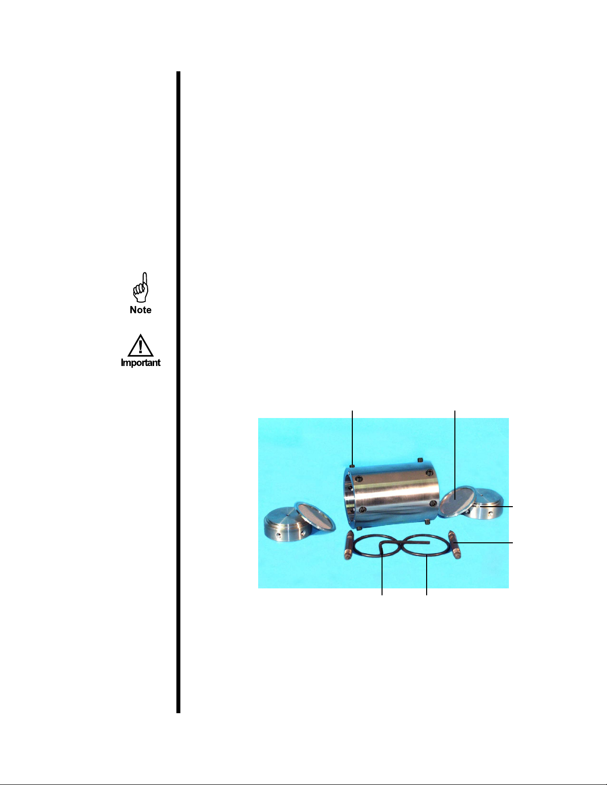
#170-45 Test Cell Assembly, Double-Capped for Cement Testing,
With Cement Screens, 2,000 PSI
#170-13-3 O-ring,Viton,Qty:4
#170-16 ValveStem,Qty:2
#170-17 ValveStemO-ring,Qty:4
#170-18 DetachableScreen,325-Meshwith60-MeshBackup,Qty:2
#170-24 2,000-PSIEndCap,Qty:2
#170-26-1 HardenedLockingScrew,Qty:12
#170-27 " Allen Wrench
#170-45-3 Cell Body
#171-24 1350 / 750 PSI (9,308 / 5,171 kPa) Nitrogen Manifold
#142-39 PipePlug,¼",Qty:2
#170-20 Manifold Block
#170-32 NeedleValve,Male,⅛"×⅛"NPT
#171-23-1 Safety Pin with Lanyard
#171-24-002 Regulator,Qty:2

OFITE, 11302 Steeplecrest Dr., Houston, TX 77065 USA / Tel: 832-320-7300 / Fax: 713-880-9886 / www.ote.com 4
#171-24-1 Chrome Nut, R.H., Reg Inlet CGA-580
#171-24-2 Nipple with Filter
#171-24-3 Fitting,¼"Flare×⅛"FNPTFemale
#171-24-5 Fitting,¼"NPTStreetTee,316StainlessSteel,Qty:2
#171-25-1 Relief Valve set at 750 PSI (5,171 kPa)
#171-25-2 Relief Valve set at 1,350 PSI (9308 kPa)
#171-26 5,000# Hose, "×3',Qty:2
#171-28 Dual Manifold Body
#171-38 Gauge, 1,000 PSI, 2½", ¼" NPT Bottom
#171-40 Gauge, 1,500 PSI, 2½", ¼" NPT Bottom
#171-42 Gauge, 3,000 PSI, 2½", ¼" NPT Bottom
#171-90-06 ReducingBushing,¼"MNPT×⅛"FNPT,316Stainless
#171-90-07 HexNipple,¼"NPT,Qty:2
#171-90-13 Fitting, ¼" Flare × ¼" Male NPT
Optional:
#170-37 Nitrogen Cylinder, 21" × 7", Right-hand Thread
#170-00-2-SP Spare Parts for One Year:
#143-00-1 Diaphragm for Airco Regulator
#143-07 Repair Kit for #143-00 Regulator
#153-14 GlassGraduatedCylinder,50mL×1mL,Qty:2
#154-10 Dual-Scale Thermometer with Metal Dial, 5" Stem,
50° – 500°F (10° – 260°C)
#170-07 O-ringforBackPressureReceiver,Qty:3
#170-13-3 TestCellO-ring,Viton,Qty:24
#170-16 ValveStem,Qty:4
#170-17 ValveStemO-ring,Qty:48
#170-18 Detachable Screen with 325 Mesh and 60 Mesh Backup,
Qty:4
#170-26-1 HardenedLockingScrew,Qty:24
#171-23-1 SafetyPinwithLanyard,Qty:2

OFITE, 11302 Steeplecrest Dr., Houston, TX 77065 USA / Tel: 832-320-7300 / Fax: 713-880-9886 / www.ote.com 5
Safety Nitrogen must be supplied in an approved Nitrogen gas cylinder and secured
to meet safety standards.
Do not use Nitrous Oxide cartridges as pressure sources for high-
temperature, high-pressure (HTHP) ltration. Under high temperature
and pressure, Nitrous Oxide can detonate in the presence of grease, oil,
or carbonaceous materials. Nitrous Oxide cartridges are to be used only
for Garrett Gas Train Carbonate Analysis.
Due to the high temperatures and pressures involved in this test, extreme
care must be exercised at all times. All safety precautions must be met,
especiallyinthecellbreakdownprocedureaftertheltrationprocedurehas
been completed.

OFITE, 11302 Steeplecrest Dr., Houston, TX 77065 USA / Tel: 832-320-7300 / Fax: 713-880-9886 / www.ote.com 6
Diagrams
Heating Jacket
(#170-00-1 or #170-01-1)
Cell Cap (#170-24)
Test Cell (#170-45)
Back Pressure Receiver
(#170-06-1)
Bleeder Valve (#170-32)
O-ring (#170-13-3)
Locking Screw (#170-26-1)
Valve Stem (#170-16)
Screen (#170-18)
Safety Pin (#171-23-1)
With Lanyard
Bleeder Valve (#170-32)
Manifold Block (#170-20)
Safety Pin (#171-23-1)
With Lanyard
Outlet Valve Stem
(#170-16)
Nitrogen Manifold
Primary Pressure
Gauge (#171-40)
Source Pressure
Gauge (#171-42)
Back Pressure
Gauge (#171-38)
Connect to Back
Pressure Receiver
Manifold Block
(#170-20)

OFITE, 11302 Steeplecrest Dr., Houston, TX 77065 USA / Tel: 832-320-7300 / Fax: 713-880-9886 / www.ote.com 7
1. Connect the heating well power cord to an appropriate power source.
Place a dial-type metal thermometer into the well in the heating jacket
and preheat to 10°F (6°C) above the desired test temperature. A pilot light
will come on when the heating jacket is at the desired temperature as
selected by the thermostat control knob.
2. Be sure all of the o-rings on the valve stems are in good working condition
(pliable with no nicks or cuts, etc.), and are not damaged during the
assemblyprocedures.Placeathinlmofsiliconegreaseonallo-rings.
Place an o-ring into one end of the test cell and place the screen on top of
itwiththeatsidefacingdown.Slowlypushoneofthecellcapsintothe
cell, making sure the arrow on the cap lines up with the arrow on the cell
body. Tighten the locking screws with the supplied allen wrench. Screw a
valve stem into the cell cap and tighten it completely.
Standard Buna N o-rings (#170-13) should be used only for tests up to
300°F (149°C). For tests over 300°F (149°C), use Viton®o-rings (#170-
13-3). After tests that come close to the maximum temperature, it will
probably be necessary to replace the o-rings.
If the cap locking screw seats are oval shaped and no longer
round, there is a possibility of stress failure and the cap should be
replaced.
3. PreparethetestsampleaccordingtoAPIspecications.Carefullypour
thesampleintothecell.Donotllthecellcloserthan0.5"(13mm)from
theo-ringgroovetoallowforheatexpansionoftheuid.Becarefulnotto
spilluidontheo-ringgrooveinsidethecell.
Operation
Cap Locking
Screws (#170-26-1)
Removable Screen
(#170-18)
Cell Cap O-ring
(#170-13-3)
Allen Wrench
" (#170-27)
Cell Cap
(#170-24)
Valve Stem
(#170-16)

OFITE, 11302 Steeplecrest Dr., Houston, TX 77065 USA / Tel: 832-320-7300 / Fax: 713-880-9886 / www.ote.com 8
4. Repeat step 2 on the other end of the cell.
Needle Valve
(#170-32)
Safety Pin
and Lanyard
(#171-23-1)
Needle Valve
(#170-32)
Manifold Block
(#170-20)
Back Pressure
Receiver
(#170-06-1)
5. Place the cell in the heating jacket. Rotate the cell in the heating jacket
so that the pin in the bottom of the heating well seats into the hole in the
bottom of the cell. This will anchor the cell inside the well and prevent the
cell from rotating as the valve stems are opened and closed. Transfer the
thermometer from the heating jacket to the thermometer well within the
cell.
6. Connect the pressuring assembly to the top valve stem and lock it in
place with the retaining pin. Place the back pressure receiver on the
bottom valve assembly and also lock it in place with the retaining pin.
Cap Locking Screws
(#170-26-1) Arrows
7. Unscrew the T-screws (counter-clockwise) on the pressure manifold to
make sure both regulators are completely closed. Connect a nitrogen
cylinder (at least 1,500 PSI) to the center inlet on the pressure manifold.
Open the pressure release valve on the nitrogen bottle and note the bottle
pressure as registered on the middle manifold gauge.

OFITE, 11302 Steeplecrest Dr., Houston, TX 77065 USA / Tel: 832-320-7300 / Fax: 713-880-9886 / www.ote.com 9
8. Keeping the valve stems closed, adjust the two regulators on the nitrogen
manifold to the recommended back pressure for your test (refer to the
chart below). Open (loosen) the top valve stem ½ turn to pressurize the
sample.Maintainthispressureontheuiduntilthedesiredtemperature
is stabilized as indicated by the thermometer. The heating time of the
sample should never exceed one hour.
The upper and lower limits of the test pressure differential are determined
by the test temperature. As this temperature exceeds 212°F (100°C), the
back pressure must be increased in order to prevent vaporization of the
ltrate.The1,000PSIdifferentialpressuremustbemaintained,sothetop
pressure will have to be increased accordingly. The table below shows
the pressures recommended for various test temperatures.
Recommended Minimum Back Pressure
Test Temperature Vapor Pressure Minimum Back Pressure
°F °C PSI kPa PSI kPa
212 100 14.7 101 100 690
250 121 30 207 100 690
300 149 67 462 100 690
350 177 135 932 160 1,104
400* 204 247 1,704 275 1,898
500* 260 680 4,692 700 4,830
*For tests above 400°F, use Teon o-rings.
9. Whentheuidsamplereachesthedesiredtesttemperature,increasethe
primary pressure (the regulator on the left) to 1,000 PSI (3,448 kPa) more
than the back pressure. Open (loosen) the bottom valve stem ½ turn to
initiateltration.
10. Collecttheltratefor30minutesmaintainingtheselectedtest
temperature within ± 5°F (± 3°C). If the back pressure rises above the
recommended setting during the test, cautiously reduce the pressure by
openingthevalveonthereceiveranddrawingoffsomeoftheltrateinto
the graduated cylinder.
11. At the end of the test, close (tighten) the top and bottom valve stems to
seal off the cell. Turn the regulator t-screws counter-clockwise to close off
theowofpressurizedgas.Openthevalveonthebackpressurereceiver
tocollectalloftheltrateinthegraduatedcylinder.Releasetheremaining
pressure from the nitrogen manifold by opening the bleeder valve on the
manifold block.

OFITE, 11302 Steeplecrest Dr., Houston, TX 77065 USA / Tel: 832-320-7300 / Fax: 713-880-9886 / www.ote.com 10
12. Remove the top and bottom valve stem retaining pins and remove the
manifoldblockandthebackpressurereceiver.Drainanyresidualltrate
collected in the receiver into the graduated cylinder. Remove the cell from
the heating jacket after once again checking that the cell valve stems are
tightly closed. Allow it to cool to room temperature or quick cool the cell by
immersion in cool water.
Pressure inside the sample cell will still be approximately 1,000 PSI
(3,450 kPa). Keep the cell upright and cool it to room temperature
before disassembling. The cell must be cool for at least one hour
at room temperature or at least 10 minutes in cool water before
loosening the cap locking screws and removing the cell cap.
13. Correctthetotalltratevolumecollectedtoastandardltrationtest
area of 7.1 in2(45.8 cm2)bydoublingtheltratevolumecollectedin
30minutes.Recordthistotalltratevolume(doubled),temperature,
pressure, and time.
14. Placethecooledcelluprightwiththeoutlet(capside)orltersidedown.
Open (loosen) the inlet valve stem to bleed off pressure from the cell
body.
It is a good idea to open the valve stem with the cell inside a sink, or with a
rag over the valve stem in order to catch any liquid that might be ejected.
15. Loosen, but do not remove, the six cap locking screws, and separate the
capfromthecellwithaslightrockingmotion.Discardtheuidinsidethe
cell unless it is required for further testing.
16. Clean and dry the apparatus thoroughly after each use. Inspect and, if
necessary, replace all of the o-rings.

OFITE, 11302 Steeplecrest Dr., Houston, TX 77065 USA / Tel: 832-320-7300 / Fax: 713-880-9886 / www.ote.com 11
Warranty and
Return Policy
Warranty:
OFI Testing Equipment, Inc. (OFITE) warrants that the products shall be free from liens and defects in
title,andshallconforminallrespectstothetermsofthesalesorderandthespecicationsapplicableto
the products. All products shall be furnished subject to OFITE’s standard manufacturing variations and
practices. Unless the warranty period is otherwise extended in writing, the following warranty shall apply:
if, at any time prior to twelve (12) months from the date of invoice, the products, or any part thereof, do
notconformtothesewarrantiesortothespecicationsapplicablethereto,andOFITEissonotiedin
writing upon discovery, OFITE shall promptly repair or replace the defective products. Notwithstanding
the foregoing, OFITE’s warranty obligations shall not extend to any use by the buyer of the products in
conditions more severe than OFITE’s recommendations, nor to any defects which were visually observable
by the buyer but which are not promptly brought to OFITE’s attention.
In the event that the buyer has purchased installation and commissioning services on applicable products,
the above warranty shall extend for an additional period of twelve (12) months from the date of the original
warranty expiration for such products.
In the event that OFITE is requested to provide customized research and development for the buyer,
OFITE shall use its best efforts but makes no guarantees to the buyer that any products will be provided.
OFITE makes no other warranties or guarantees to the buyer, either express or implied, and the warranties
provided in this clause shall be exclusive of any other warranties including ANY IMPLIED OR STATUTORY
WARRANTIES OF FITNESS FOR PURPOSE, MERCHANTABILITY, AND OTHER STATUTORY
REMEDIES WHICH ARE WAIVED.
This limited warranty does not cover any losses or damages that occur as a result of:
• Improper installation or maintenance of the products
• Misuse
• Neglect
• Adjustment by non-authorized sources
• Improper environment
• Excessive or inadequate heating or air conditioning or electrical power failures, surges, or other
irregularities
• Equipment, products, or material not manufactured by OFITE
• Firmwareorhardwarethathavebeenmodiedoralteredbyathirdparty
• Consumable parts (bearings, accessories, etc.)
Returns and Repairs:
Items being returned must be carefully packaged to prevent damage in shipment and insured against
possibledamageorloss.OFITEwillnotberesponsibleforequipmentdamagedduetoinsufcient
packaging.
Any non-defective items returned to OFITE within ninety (90) days of invoice are subject to a 15%
restocking fee. Items returned must be received by OFITE in original condition for it to be accepted.
Reagents and special order items will not be accepted for return or refund.
OFITE employs experienced personnel to service and repair equipment manufactured by us, as well as
other companies. To help expedite the repair process, please include a repair form with all equipment
sent to OFITE for repair. Be sure to include your name, company name, phone number, email address,
detailed description of work to be done, purchase order number, and a shipping address for returning the
equipment. All repairs performed as “repair as needed” are subject to the ninety (90) day limited warranty.
All“CertiedRepairs”aresubjecttothetwelve(12)monthlimitedwarranty.
Returns and potential warranty repairs require a Return Material Authorization (RMA) number. An RMA
form is available from your sales or service representative.
Please ship all equipment (with the RMA number for returns or warranty repairs) to the following address:
OFI Testing Equipment, Inc.
Attn: Repair Department
11302 Steeplecrest Dr.
Houston, TX 77065
USA
OFITE also offers competitive service contracts for repairing and/or maintaining your lab equipment,
including equipment from other manufacturers. For more information about our technical support and
repair services, please contact techservice@ote.com.
This manual suits for next models
1
Table of contents
Other OfiTE Test Equipment manuals
Popular Test Equipment manuals by other brands

Reach Technology
Reach Technology PoE4N/10G manual

Agilent Technologies
Agilent Technologies 85110L User's and service guide

TESTO
TESTO 0632 3301 Instruction manual and users guide

Test Equipment Depot
Test Equipment Depot Rapport 337 user manual

VIAVI Solutions
VIAVI Solutions T-BERD quick guide

Tektronix
Tektronix 2465 instruction manual