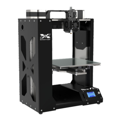
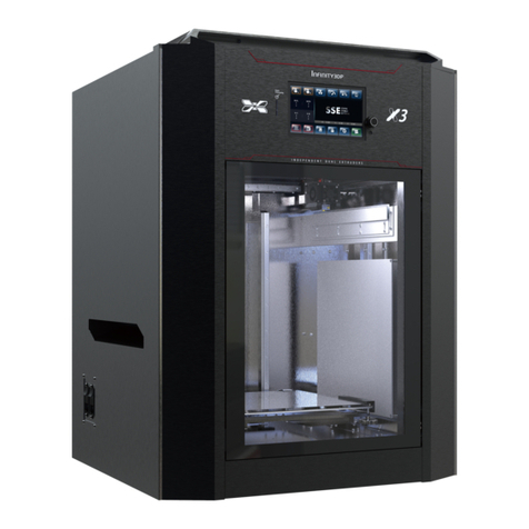
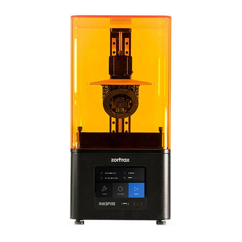
INFINITY3DP INFINITY X2 User manual

- User Manual -

1. Unpacking the X2 out of the cardboard box before doing the rest of actions.
2. Keep the X2 in a clean, dust-free and dry environment that away from fire is essential for proper operation.
3. Keep the X2 with a clean and free of obstacles build plate as to ensure a successful leveling.
4. X2 generates high temperatures as the nozzle can reach up to 500°C (932°F),
the build plate up to 130°C (266°F) that may cause injury. Never reach inside of the X2 while it is in operation.
5. Avoiding vibrate the components or open the cabinet door during printing by improper operation
as to prevent any damages.
6. Leave the machine do certain action automatically should protect the mainboard caused by reverse current.
7. Remain the structural integrity of the X2 as to ensure the safety and the utility of authorized maintenance.
8. Please aware of the warning labels and operate the X2 carefully.
9. Always read the safety statements, and be aware of the following safety signs when you see them on the printer.
Warnings and Cautions precede the paragraph to which they pertain.
CAUTION
This manual describes the application operation of the precision electronic machine.
Please read and understand the user manual carefully.
Failure to read the manual may lead to personal injury, or damage to the INFINI T Y3DP X2.
If any errors in operating or specific problems,
please contact our technical team via website or Facebook for timely support.
Keep b ody par ts
out of t he
moti on path
Movi ng Par ts
Hot
Parts
Do not touch unless wait 1.5 hour
after turning off the power
Hot
Par ts

TABLEOF
CONTENTS SPECIFICATIONS
UNBOXING
ACCESSORIES
BUILD PLATE INSTALLATION/REMOVE
HARDWARE INSTALLATION
WELCOME SETUP
BUILD PLATE LEVELING
FILAMENT LOADING
FILAMENT UNLOADING/REPLACEMENT
START A PRINT
FILAMENT RUN-OUT SENSOR
COMPLETE A PRINT
CALIBRATION(DURING PRINTING)
CALIBRATION(DURING PRINTING)_NOZZLE TEMPERATURE
CALIBRATION(IDLE STATE)_NOZZLE TEMPERATURE
CALIBRATION(DURING PRINTING)_BUILD PLATE TEMPERATURE
CALIBRATION(IDLE STATE)_BUILD PLATE TEMPERATURE
CALIBRATION(DURING PRINTING)_FAN SPEED
CALIBRATION(IDLE STATE)_FAN SPEED
CALIBRATION(DURING PRINTING)_PRINT SPEED
CALIBRATION(DURING PRINTING)_DYNAMIC Z OFFSET
CALIBRATION(IDLE STATE)_Z-AXIS ZERO POSITION
CALIBRATION(IDLE STATE)_MOVEMENT OF HOTEND MODULE (X, Y, Z, E)
CALIBRATION(IDLE STATE)_HOTEND REPLACEMENT
MAINTENANCE_BELT
MAINTENANCE_EXTRUDER
MAINTENANCE_TROUBLESHOOTING
01
02
03
04
06
07
08
09
12
13
14
15
16
17
18
19
20
21
22
23
24
25
26
27
29
33
35
INTRODUCTION
PREPARATION
OPERATION
CALIBRATION
MAINTENANCE

SPECIFICATIONS
Dimensions
Build Volume
Language Support
Print Technology
Printer Structure
Layer Resolution
Nozzle Diameter
Nozzle Temperature
Extruder Type
Build Plate Temperature
Build Plate Leveling
Fan Cooler
Driver
XY Axis
Z Axis
Stepper Motor
Electrical Controller
Electrical Control
Precaution Mechanism
Filament Diameter
Supported Filament
Flexible Material
Connectivity
Power Input
Slicer
Net Weight
W504 x D562 x H600 mm (W20”x D22” x H24”)
300 x 300 x 260mm (11.8” x 11.8” x 10.2”)
Chinese, English, Japanese
FDM
Enclosed Chamber
0.01mm
0.5mm (default)|0.4,0.6,0.8mm
350°C (default)|500°C
Direct Extruder (One-clip Removable Hotend Module)
up to 130°C (266°F)
Pre-calibration
Dual / 45mm
Infinity3DP GT81
Japan, THK Caged Ball Linear Guide (Model SRS)
Japan, THK Ball Screws (Accuracy Grades C3)
Japan, THK Caged Ball LM Guide (Model SHS) *2
57mm 0.9°
32bit MCU
Germany, igus Chainflex® Flexible Cables
Filament Run-out Sensor
1.75 mm
PLA/ABS/Nylon/Carbon-Nylon/PETG/PC/Flexible/
Glass Wool Filled PP/ASA/PPS/PEKK/PEEK+CF/PEEK+GF
Printable (Shore 50A)
SD card
100-120 V; 50/60 Hz; 12A or 200-240 V; 50/60 Hz; 7.5A, 600W
Cura Infinity3DP Edition
35kg / 77 Ibs
01

Step 1: Pull out the tenons on the bottom of carton.
Step 2: Unboxing the X2.
Step 3: Pull out the X2 with side handles.
Step 4: Accessories Kit would be put underneath the build
platform of the X2.(See page 3 for details)
02
UNBOXING

03
ACCESSORIES
Please review and check the included accessories packed as below:
1. SD card *1 <plug on 3D printer>
2. Glue Sticks *1
3. Filament Rack (Top Feeding)*1
4. Filament Holder (Side Feeding)*2
5. Power Cord (NEMA 5-15P to IEC C13 ) *1 (Option -110v or 220v)
6. Build Plate_Borosilicate Glass*1 <assembled on 3D printer>
7. Warranty Card *1
8. USB Cable *1
9. Cleaning Brush (Steel) *1
10. Scraper *1
11. Maintenance Kit *1
⼤陸的X2X3 台灣全球的
X2X3
X1

REMOVE
Step 1:Pull the board clip toward front as to loosen the build plate and platform.
Step 2:Pull slightly up the build plate and apart the clips behind.
04
BUILDPLATEINSTALLATION/REMOVE
The actions are limited to the cool-down (room temperature) build platform.

05
BUILDPLATEINSTALLATION/REMOVE
05
The actions are limited to the cool-down (room temperature) build platform.
INSTALLATION
Step 1:Insert with build plate to the clean build platform and tighten with the clips behind.
Step 2:Buckle the board clips on the sides.

Step 1: Connect power cord to the side of X2.
Step 2: Place filament on the rack (top) or holder (side).
※ Top feeding suggest for flexible materials; Side feeding suggest for others.
※ Make sure to put the rack with the filament as the direction of below picture.
06
HARDWAREINSTALLATION
06

Step 1: Turn on the printer using the power switches on the side of X2.
Step 2: The Actuator would move from side to side and back to home position.
X, Y, Z axis would run to home position and ready to print.
07
WELCOMESETUP

Step 1: Select Build Plate Leveling icon,
the build plate will automatically level to a designated height.
Step 2: Select one corner of the nine-square grids,
hotend module would move to the designated position.
Step 3: Put a piece of standard paper (thickness of 100gsm) between
the nozzle and the build plate after platform leveled.
Step 4: Rotate the bottom knurled nut to roughly adjust the distance between
the nozzle and the build plate until tighten the paper.
Step 5: Repeat for all four corners with above procedures for completing the
build plate leveling adjustment.
BUILDPLATELEVELING
08
OK Cancel
Remind
Are you sure to adjust?
※ Please DO NOT randomly click the icons.
The reaction and operating procedure would be more complex,
please contact INFINITY3DP for further instruction if necessary.
※ Rotate the knurled nut in counterclockwise would
increase the distance between the nozzle and the build plate.
※ Rotate the knurled nut in clockwise would
decrease the distance between the nozzle and the build plate.

09
FILAMENTLOADING
Side Feeding
Step 1: Insert and push the sharp-pointed tip of filament gently into the side feeding,
until it reaches the end of the hotend module. Wait for heated nozzle for continue.
(Side Feeding)

10
FILAMENTLOADING
A
C
B
Top Feeding (Suggest for flexible materials)
Step 1: A –Pull the tube (long) out of the hotend module and fix it on side corner of the
inner printer (as picture). Insert the tube (short) on the hotend module.
B –Insert the sharped-pointed tip filament into the tube outside of X2.
C –Grab it from inner side, insert and push gently into the tube on hotend module
until reach the end. Wait for heated nozzle for continue.
(Top Feeding )

FILAMENTLOADING
Step 2: Select “Calibration” icon on the menu for setting the assigned temperature
of filament and wait for X2 to heat up the nozzle till the actual temperature
reached as setting.
Step 3: Press the clip on the hotend module till the Release Button up.
Step 4: Push the filament gently until it comes out of the nozzle.
Step 5: Press the Release Button and the clip would back to grab the filament for completing the loading.
11
(Top Feeding )(Side Feeding)
※ Temperature set-up procedure, see page 18.
Nozzle
Curr.:215
Targ.:215°c

Step 1: Heat up the nozzle until the filament melted with its target temperature.
Step 2: Press the clip on the hotend module till the Release Button up as to loosen the filament.
Step 3: (A) Pull out the existed filament firstly.
(B) Insert and push gently the sharp-pointed filament until it comes out of the nozzle.
Step 4: Press the and the clip would back to tighten the filament for completing the changing.Release Button
Nozzle
Curr.:215
Targ.:215°c
12
FILAMENTUNLOADING/REPLACEMENT
※ Temperature set-up procedure, see page 18.
B
A
(Side feeding as example)

Step 1: Insert SD card; select the“SD Card” icon.
Step 2: Select one of the files (gcode) and confirm to print.
※ The default print files (gcode) on the SD card are ABS particular; Please loading ABS for your initial tested print.
※ Print with filament-PLA: We suggest opening the front door and top cover while printing. Otherwise, keep it closing while printing.
13
STARTAPRINT
SD:
IX2_10hex20cm_ABS.gcode
IX2_moai_ABS.gcode
IX2_X2_280280 03_ABS.gcode
SD:
IX2_10hex20cm_ABS.gcode
IX2_moai_ABS.gcode
IX2_X2_280280 03_ABS.gcode
OK Cancel
Start a Print
IX2_moai_ABS.gcode

3dp file 02.gcode
Nozzle : 215 °c
H. Bed: 102 °c
00d00h-19m44s
OK
Remind
Continue printing?
3dp file 02.gcode
Nozzle : 215 °c
H. Bed: 102 °c
00d00h-19m44s
OK
Remind
Stop printing?
The printing procedure would pause and alert a notice when sensor detected the condition of filament run-out.
Step 1: Replace the filament. ※ see page 12.
Step 2: Select the for completing the replacement. or
14
FILAMENTRUN-OUTSENSOR
3dp file 02.gcode
Nozzle : 215 °c
H. Bed: 102 °c
00d00h-19m44s
3dp file 02.gcode
Nozzle : 215 °c
H. Bed: 102 °c
00d00h-19m44s
OK
Remind
Out of Filament!

When the print finished, wait for the build plate cooling down and back to home position;
take the print and build plate out of X2 then grab the print from it.
※ Once take apart the print from “heating build plate”, there would be possible injure or print defect.
15
COMPLETEAPRINT
04

16
CALIBRATION(DURINGPRINTING)
During printing, select the “Menu” icon (in ) for switching the calibration item. GREEN
Click the once > Calibration of Nozzle Temperature
Continue click the icon, it will show as followed:GREEN
1.Calibration of Build Plate Temperature
2.Calibration of Fan Speed
3.Calibration of Print Speed
4.Calibration of Dynamic Z Offset
3dp file 02.gcode
Nozzle : 215 °c
H. Bed: 102 °c
00d00h-19m44s
Back to MENU
Dynamic Z Offset
Nozzle Temperature
Build Plate Temperature
Fan SpeedPrint Speed
NOZZLE
Curr.:215
Targ.:215°c
FAN
Curr.: 35
Targ.: 35%
SPEED
Curr. : 100 %
Min. : 10 %
Max.: 250 %
BED
Curr.:95°c
Targ.:100°c
Z Adjust
Curr. : 009.76
Min. : 000.00
Max.: 012.00

17
CALIBRATION(DURINGPRINTING)_NOZZLETEMPERATURE
Set the nozzle temperature with separate stages (as picture).
1) The page icon-Nozzle Temperature
2) Stop the action (increasing/decreasing the temperature)
3) Reduce the nozzle temperature
4) Increase the nozzle temperature
5) The unit of parameter for reducing or increasing the nozzle temperature
6) The unit of parameter is selected. (Triangle icon)
7) Current Nozzle Temperature
8) Target Nozzle Temperature
9) Back to the front page
Step 1: Continue click the icon > Calibration of Nozzle Temperature > select the unit of temperatureGREEN
Step 2: Choose or adjusting the nozzle temperature. The current temperature would meet the target temperature.
Example: Current nozzle temperature 60°C, set 10 (the unit of temperature) and click once.
The current nozzle temperature would be 70°C, one click for up 10 degree at a time.
※ It would be better take the median of suggested temperature when printing with unfamiliar material for the first time.
Above seng is parcular for the prompt adjustment.
We suggest seng the parameter via the slicing soware.
NOZZLE
Curr.:60°c
Targ.:70°c
NOZZLE
Curr.:70°c
Targ.:70°c
NOZZLE
Curr.:60°c
Targ.:60°c
NOZZLE
Curr.:215
Targ.:215°c
3dp file 02.gcode
Nozzle : 215 °c
H. Bed: 102 °c
00d00h-19m44s
Table of contents
Other INFINITY3DP 3D Printer manuals
