Infinova V5422IR-A8065ST-W User manual

INSTRUCTION MANUAL
V5422IR-A8 Series
High Resolution Day/Night IR Minidome
Camera

Notice
Copyright Statement
This manual may not be reproduced in any form or by any means to create any
derivative such as translation, transformation, or adaptation without the prior
written permission of Infinova.
Infinova reserves the right to change this manual and the specifications without
prior notice. The most recent product specifications and user documentation for
all Infinova products are available on our web site www.infinova.com.
Trademarks
Infinova
® is a trademark of Infinova.
All other trademarks that may appear belong to their respective proprietors.
FCC Warning
The V5422IR-A8 series High Resolution Day/Night IR minidome cameras
comply with the FCC rules.
Operation is subject to the following two conditions:
This device will not cause harmful interference.
This device must accept any interference received, including interference
that may cause undesired operations.
The The V5422IR-A8 series High Resolution Day/Night IR minidome cameras
have been tested and found to comply with the limits for a Class A digital
device, pursuant to the FCC rules. With these rules and regulations being
obeyed to maintain the good working condition of device, the operation is not
supposed to be affected by external interruptions under certain circumstances.
This device is electromagnetic, so all the installation and application processing
along the device has to follow strictly to the manual or it may hamper the
telecommunication around. Meanwhile, there is no guarantee that interference
will not occur in a certain particular installation situation.

Read this manual carefully before installation. This manual
should be saved for future use.
Important Safety Instructions and Warnings:
Electronic devices must be kept away from water, fire or high magnetic
radiation.
Clean with a dry cloth.
Provide adequate ventilation.
Unplug the power supply when the device is not to be used for an extended
period of time.
Only use components and parts recommended by manufacturer.
Position power source and related wires to assure to be kept away from
ground and entrance.
Refer to qualified personnel for all service matters.
Save product packaging to ensure availability of proper shipping containers
for future transportation.
Indicate that the un-insulated components within the product may carry a
voltage harmful to humans.
Indicate operations that should be conducted in strict compliance with
instructions and guidelines contained in this manual.
Warning: To avoid risk of fire and electric shock, keep the product away
from rain and moisture!

CONTENTS
Chapter I System Introduction....................................................................... 1
1.1 Product Description............................................................................. 1
1.2 Product Features................................................................................. 2
1.3 Product Model...................................................................................... 3
1.4 Specifications....................................................................................... 4
1.5 Notice .................................................................................................... 6
Chapter II Menu Settings................................................................................ 7
2.1 Image..................................................................................................... 7
2.2 Advanced.............................................................................................. 8
2.2.1 Zone Masking ·····························································8
2.2.2 Motion Detection ·························································9
2.3 Day & Night .......................................................................................... 9
2.4 Language.............................................................................................. 9
2.5 Load Default......................................................................................... 9
2.6 Soft Version.......................................................................................... 9
2.7 Save & Exit........................................................................................... 9
2.8 Exit....................................................................................................... 10
Appendix I Cable Diameter Calculation and Lightning & Surge Protection
...........................................................................................................................11


1
CHAPTER I SYSTEM INTRODUCTION
1.1 Product Description
Thank you very much for purchasing our product!
V5422IR-A8 series high resolution day/night IR minidome camera is specially
designed by Infinova for the surveillance application of elevators. This camera
adopts 1/1.9" progressive scan CMOS sensor. With built-in 2.8mm fixed lens
and high resolution of 800 TV lines, users can acquire better image quality. It
also boasts of low illumination, excellent color rendering ability and digital
noise reduction function. This camera also has infrared night vision function, so
it can still surveille the area even if there is no light. As a result, 24 hours
continuous surveillance can be achieved.
This camera supports OSD menu display function. It’s friendly and intuitive
user-interface make it easy to operate.
This camera supports privacy mask which up to 8 masks, so it can protect the
privacy area effectively. Besides, its motion detection function makes your
surveillance area safer.

2
1.2 Product Features
Infinova’s V5422IR-A8 series camera has the following features and functions:
1/3" progressive scan CMOS sensor
High Resolution: 800TV lines
IR-Cut Removable (ICR) Filter for Day/Night switching
15m IR Range
Supports OSD menu display function
3D noise reduction
Auto electronic shutter
Auto white balance: rich modes of auto white balance
Real and natural color reproduction
Supports image enhancement
Supports digital zoom
Motion detection up to 4 areas
Privacy mask up to 8 programmable masks
Internal synchronization
Small size, low power consumption and simple installation
3-axis adjustment
Twelve volts of direct current (12VDC)

3
1.3 Product Model
This manual is for the following models:
V5422IR-A8065ST-W High Resolution Day/night IR minidome camera,
1/3-inch progressive scan CMOS sensor, 2.8mm lens,
800TV lines, PAL, 15m IR range, Indoor, White
exterior, Surface mount, 12VDC
V5422IR-A8065ST-B High Resolution Day/night IR minidome camera,
1/3-inch progressive scan CMOS sensor, 2.8mm lens,
800TV lines, PAL, 15m IR range, Indoor, Grey
exterior, Surface mount, 12VDC
V5422IR-A8075ST-W High Resolution Day/night IR minidome camera,
1/3-inch progressive scan CMOS sensor, 2.8mm lens,
800TV lines, NTSC, 15m IR range, Indoor, White
exterior, Surface mount, 12VDC
V5422IR-A8075ST-B High Resolution Day/night IR minidome camera,
1/3-inch progressive scan CMOS sensor, 2.8mm lens,
800TV lines, NTSC, 15m IR range, Indoor, Grey
exterior, Surface mount, 12VDC

4
1.4 Specifications
Model V5422IR-A8 Series
Image Sensor 1/3" progressive scan CMOS
Video Format PAL/NTSC
Effective Pixels
(H×W)
PAL: 1280×960;
NTSC: 1280×952
Resolution 800TVL
Day/Night
Functionality ICR
Lens Fixed lens: F2.0, f=2.8mm
Lens Mount M12
Camera Angle
Adjustment
X (Panning): 0°~360°;
Y (Tilting): 0°~75° (-3°~0° deviation);
Z (Rotating): 0°~344°
Aperture Fixed
Sensitivity Color mode: 0.01 lux; B/W mode: 0 lux (IR ON)
S/N Ratio 50dB
Shutter Auto: 1/50000s~1/25s
Gamma
Correction 0.45
White Balance AWB-GW, AWB-CCT, AWB-PRO, AWB-TEMPORAL,
AWB-AI
Noise Reduction 3D, Auto/Manual (0~15 adjustable)
Image
Enhancement Sharpness, Contrast, Saturation
Rotating Mirror, Reverse
Digital Zoom Support, 0~5 adjustable
Privacy Mask Up to 8 programmable masks
5
Motion Detection Up to 4 programmable areas
Sync. System Internal
Video Output 1.0 Vp-p (75 Ohm)
Power Supply 12VDC, ±10%
Power
Consumption 180mA (Maximum), 12VDC
Operating
Temperature -4°F~122°F (-20°C~+50°C)
Storage
Temperature -4°F~140°F (-20°C~+60°C)
Operating
Humidity 0%-90% RH (non-condensing)
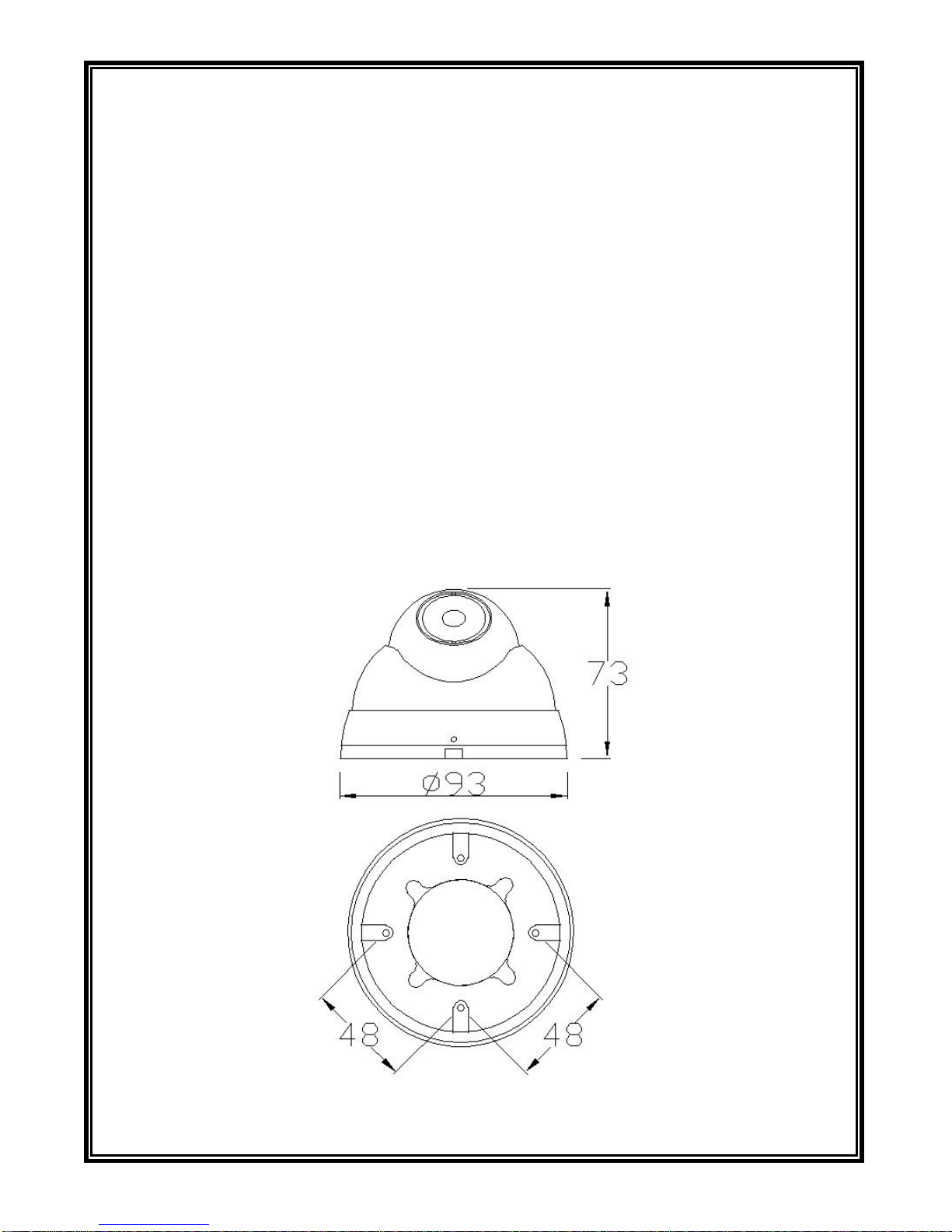
Unit Dimensions
(H×Ф) 2.87"×Ф3.66" (73mm×93mm)
6
1.5 Notice
1. Do not place the camera under strong light for fear of damaging the CMOS
chip.
2. Do not directly touch the CMOS element. If it is necessary to clean the
element, use a soft cloth moistened with alcohol to wipe off the dust.
3. When utilizing power supply, please refer to our specifications.
4. Camera should be firmly installed so that the damage of people or other
objects for its precariousness and fall can be avoided.
5. Do not put the camera near or above the radiator or heating resistor.
6. Please be careful and avoid intense impact when using the camera.
7. Please refer to the following dimension figure when installing this product.
(Unit: mm)

7
CHAPTER II MENU SETTINGS
Main menu settings are as follows:
MAINMENU
IMAGE ↲
ADVANCED ↲
DAY&NIGHT EXTERNAL
LANGUAGE ENGLISH
LOAD DEFAULT
SOFT VERSION V2.00.00
SAVE&EXIT
EXIT
2.1 Image
3D-DNR ↲
IRIS ↲
EXPOSURE CONTROL ↲
WB ↲
IMAGE ENHANCE ↲
ZOOMIN 0
RETURN ↲
8
2.2 Advanced
ZONEMASKING ↲
MOTION DETECTION ↲
MIRROR OFF
FLIP OFF
RETURN ↲
2.2.1 Zone Masking
COLOR MOSAIC
AREANO.1 ↲
AREANO.2 ↲
AREANO.3 ↲
AREANO.4 ↲
AREANO.5 ↲
AREANO.6 ↲
AREANO.7 ↲
AREANO.8 ↲
RETURN ↲
9
2.2.2 Motion Detection
SENSITIVITY HIGH
AREANO.1 ↲
AREANO.2 ↲
AREANO.3 ↲
AREANO.4 ↲
RETURN ↲
2.3 Day & Night
DAY&NIGHT EXTERNAL【COLOR/B&W/AUTO】
2.4 Language
LANGUAGE ENGLISH【中文】
2.5 Load Default
LOAD DEFAULT
2.6 Soft Version
SOFT VERSION V2.00.00
2.7 Save & Exit
SAVE&EXIT

10
2.8 Exit
EXIT

11
APPENDIX I CABLE DIAMETER CALCULATION AND
LIGHTNING & SURGE PROTECTION
Relation between 24VAC Cable Diameter and Transmission Distance
In general, the maximum allowable voltage loss rate is 10% for AC-powered devices. The table below
shows the relationship between transmission power and maximum transmission distance under a certain
specified cable diameter, on condition that the 24VAC voltage loss rate is below 10%. According to the
table, if a device rated at 50W is installed 17-meter away from the transformer, the minimum cable
diameter shall be 0.8000mm. A lower diameter value tends to cause voltage loss and even system
instability.
0.8000 1.000 1.250 2.000
10 283 (86) 451 (137) 716 (218) 1811 (551)
20 141 (42) 225 (68) 358 (109) 905 (275)
30 94 (28) 150 (45) 238 (72) 603 (183)
40 70 (21) 112 (34) 179 (54) 452 (137)
50 56 (17) 90 (27) 143 (43) 362 (110)
60 47 (14) 75 (22) 119 (36) 301 (91)
70 40 (12) 64 (19) 102 (31) 258 (78)
80 35 (10) 56 (17) 89 (27) 226 (68)
90 31 (9) 50 (15) 79 (24) 201 (61)
100 28 (8) 45 (13) 71 (21) 181 (55)
110 25 (7) 41 (12) 65 (19) 164 (49)
120 23 (7) 37 (11) 59 (17) 150 (45)
130 21 (6) 34 (10) 55 (16) 139 (42)
140 20 (6) 32 (9) 51 (15) 129 (39)
150 18 (5) 30 (9) 47 (14) 120 (36)
160 17 (5) 28 (8) 44 (13) 113 (34)
170 16 (4) 26 (7) 42 (12) 106 (32)
180 15 (4) 25 (7) 39 (11) 100 (30)
190 14 (4) 23 (7) 37 (11) 95 (28)
200 14 (4) 22 (6) 35 (10) 90 (27)
Power (W)
Diameter (mm)
Distance (ft / m)

12
Lightning & Surge Protection
The product adopts multi-level anti-lightning and anti-surge technology integrated with gas discharge tube,
power resistor and TVS tube. The powerful lightning and surge protection barrier effectively avoids
product damage caused by various pulse signals with power below 4kV, including instantaneous lightning,
surge and static. However, for complicated outdoor environment, refer to instruction below for lightning
and surge protection:
The product features with dedicated earth wire, which must be firmly grounded. As for surveillance
sites beyond the effective protection scope, it’s necessary to erect independent lightening rods to
protect the security devices. It’s recommended to separate the lightning rod from the mounting pole,
placing the rod on an independent pole, as shown in the figure below. If the product has to be installed
on the same pole or pedestal for lightning rod, there should be strict insulation between the video cable
BNC terminal, power cable, control cable and the standing pole of the lightning rod.
For suburb and rural areas, it’s recommended to adopt direct burial for the transmission cables.
Overhead wiring is prohibited, because it’s more likely to encounter lightning strike. Use shielded
cables or thread the cables through metal tubes for burial, thus to ensure the electric connection to the
metal tube. In case it’s difficult to thread the cable through the tube all the way, it’s acceptable to use
tube-threaded cables only at both ends of the transmission line, yet the length in burial should be no
less than 15 meters. The cable sheath and the tube should be connected to the lightning -proof
grounding device.
Additional high-power lightning-proof equipment and lightning rods should be installed for strong
thunderstorm or high induced voltage areas (such as high-voltage substation).
The lightning protection and grounding for outdoor devices and wires should be designed in line with
the actual protection requirement, national standards and industrial standards.
The system should perform equipotential grounding by streaming, shielding, clamping and earthing.
The grounding device must meet anti-interference and electric safety requirements. There should be no
short-circuiting or hybrid junction between the device and the strong grid. Make sure there’s a reliable
grounding system, with grounding resistance below 4Ω(below 10Ωfor high soil resistivity regions).
The cross-sectional area of the earthing conductor should be no less than 25mm².
Lightning rod
Front device
for surveillance
system
Separated layout for the lightning
rod and the standing pole
LPZOB
LPZOA
Mounting
pole for
front device
30° 30°


Infinova
51 Stouts Lane,
Monmouth Junction, NJ 08852, U.S.A.
Tel: 1-888-685-2002 (USA only)
1-732-355-9100
Fax: 1-732-355-9101
sales@infinova.com
V1.0 1512
This manual suits for next models
3
Table of contents
Other Infinova IP Camera manuals

Infinova
Infinova V1700N-NE2 Series User manual

Infinova
Infinova V5112IR-A8 series User manual

Infinova
Infinova V6202-T03 Series User manual

Infinova
Infinova V1492N-18N05 User manual

Infinova
Infinova V6812IR-H0 Series User manual

Infinova
Infinova V6812-T00 Series User manual

Infinova
Infinova V6202IR-H02 Series User manual

Infinova
Infinova V1700N-NE2 Series User manual

Infinova
Infinova V6202-TA Series User manual

Infinova
Infinova V6202-T00 Series User manual


