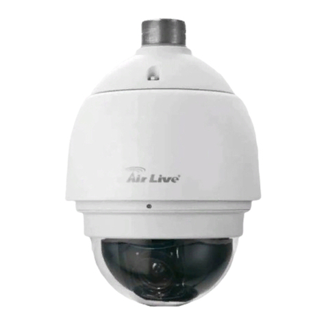
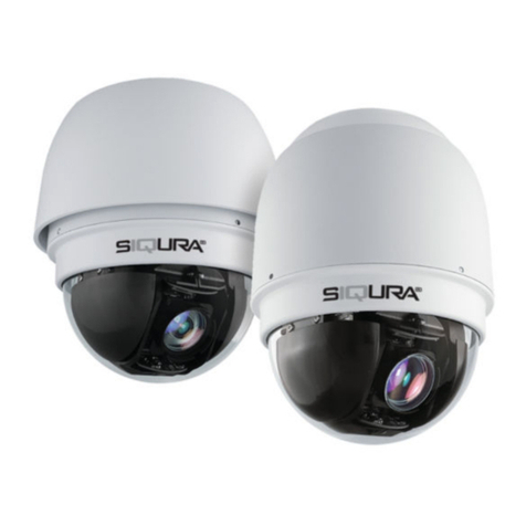
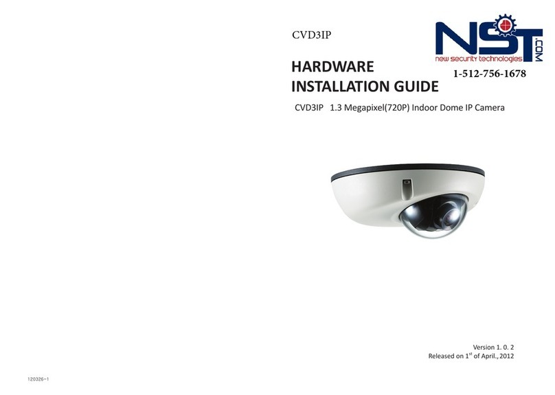
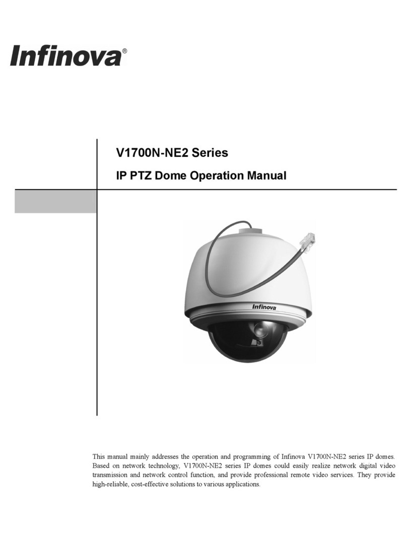
Infinova V1700N-NE2 Series User manual

V1700N-NE2 Series
IP PTZ Domes Installation Guide
Wall Mounting Corner Mounting Pole Mounting Pendant Mounting
Over-roof horizontal
Surface Mounting
Over-roof Side
Wall Mounting Ceiling Mounting Ceiling Mounting
indoor outdoor
indoor outdoor
This manual addresses the installation procedures of Infinova V1700N-NE2 series IP domes. The domes feature
an all-in-one design and compact structure that makes its installation an easy and time-saving job.
Please familiarize yourself with the instructions and guidelines discussed in this manual before attempting to
install your IP domes.


Notice
Copyright Statement
This manual may not be reproduced in any form or by any means to create any derivative such as translation, transformation, or adaptation
without the prior written permission of Infinova.
Infinova reserves the right to change this manual and the specifications without prior notice. The most recent product specifications and user
documentation for all Infinova products are available on our website www.infinova.com.
Trademarks
Infinova
®
is a trademark of Infinova.
Copyright © 1993-2012 Infinova. All rights reserved.
All other trademarks that may appear belong to their respective proprietors.
FCC Warning
The IP domes comply with the FCC rules.
Operation is subject to the following two conditions.
zThis device may not cause harmful interference.
zThis device must accept any interference received, including interference that may cause undesired operation.
The IP domes have been tested and found to comply with the limits for Class A digital device, pursuant to Part 15 of the FCC rules. These
limits are designed to provide reasonable protection against harmful interference when the equipment is operated in a residential environment.
This equipment generates, uses, and can radiate radio frequency energy and, if not installed and used in accordance with the instructions, may
cause harmful interference to radio communications. However, there is no guarantee that interference will not occur in a particular
installation.

Read this manual carefully before installation. This manual should be saved for future use.
Important Safety Instructions and Warnings
zElectronic devices must be kept away from water, fire or high magnetic radiation.
zClean with a dry cloth.
zProvide adequate ventilation.
zUnplug the power supply when the device is not to be used for an extended period of time.
zOnly use components and parts recommended by manufacturer.
zPosition power source and related wires to assure they will be kept away from ground and access way.
zRefer all service matters to qualified personnel.
zSave product packaging to ensure availability of proper shipping containers for future transportation.
zThe power should be subject to below conditions (except for ceiling mounting and pendant mounting) when 24VAC is adopted:
Technical data: Rated output 24VAC, min. 2.3A, marked "LPS" or "Class 2"
Product Category CCN(s) : QQGQ or EPBU
Required Marks of Conformity: UL+ cUL
Indicates that the un-insulated components within the product may carry a voltage harmful to humans.
Indicates operations that should be conducted in strict compliance with instructions and guidelines contained in this manual.
Warning: To avoid risk of fire and electric shock, keep the indoor product away from rain and moisture!

Table of Contents
Chapter I Precautions ...................................................................1
1.1 Be Careful During Transportation........................................1
1.2 Plan Your Installation Beforehand .......................................1
1.3 Pay Extra Care During Installation ......................................1
1.4 Take Necessary Cautions for Electrical Safety.....................1
1.5 Ensure Proper Operation and Maintenance..........................1
Chapter II Requirements and Connections.................................2
2.1 Environmental Requirements...............................................2
2.2 Wiring Requirements ...........................................................2
Chapter III Mounting ...................................................................3
3.1 Ceiling Mounting.................................................................3
3.1.1 Indoor Mounting Specifications .................................... 3
3.1.2 Outdoor Mounting Specifications.................................. 3
3.1.3 Installation Procedures for Recessed ceiling Mounting. 3
3.2 Over-roof Mounting.............................................................4
3.2.1 Over-roof Mounting Specifications............................... 4
3.2.2 Installation Procedures for Over-roof Mounting ...........5
3.3 Wall Mounting .....................................................................6
3.3.1 Specifications for Short-Arm Wall mounting................ 6
3.3.2 Specifications for Long-Arm Wall Mounting................ 6
3.3.3 Installation Procedures for Wall Mounting ................... 6
3.4 Corner Mounting..................................................................7
3.4.1 Indoor Mounting Specifications .................................... 7
3.4.2 Outdoor Mounting Specifications ................................. 7
3.4.3 Installation Procedures for Corner Mounting ................ 7
3.5 Pole Mounting .....................................................................8
3.5.1 Indoor Mounting Specifications .................................... 8
3.5.2 Outdoor Mounting Specifications ................................. 8
3.5.3 Installation Procedures for Pole Mounting .................... 9
3.6 Pendant Mounting................................................................9
3.6.1 Indoor Mounting Specifications .................................... 9
3.6.2 Outdoor Mounting Specifications ............................... 10
3.6.3 Installation Procedures for Pendant Mounting ............ 10
Appendix I DIP Setting............................................................... 11
Appendix IIAssembly and Disassembly Procedures................14
Appendix III Usage of Dustproof Sponge..................................15
Appendix IV Usage of Waterproof Tape....................................15
Appendix ⅤCable Diameter Calculation and Lightning &
Surge Protection..........................................................................16


1
Chapter I Precautions
The IP domes have been designed and manufactured to ensure
maximum reliability for various applications. However, the actual
performance may also depend on how you plan and make the
installation. Before attempting to install or operate the IP domes,
therefore, please thoroughly familiarize yourself with the following
instructions, and make sure that they are strictly followed.
1.1 Be Careful During Transportation
To avoid damage, protect the units against extremes of pressure,
shock or vibration during transportation. The products must be
shipped in parts disassembled as the original packing did, and kept
away from water, fire and high magnetic radiation. In no event will
Infinova be liable for any damage or loss arising from improper
transportation or storage.
1.2 Plan Your Installation Beforehand
zDo not install an indoor dome in outdoor environment.
zKeep the domes away from electric or magnetic fields. Devices
such as TV, audio speaker, high-capacity transformer, electric
motor and radio transmitter usually generate magnetic fields that
may distort the camera images.
zProtect the domes from dampness and dust. Do not install the
domes where the humidity is over 90%, or where there is greasy
smoke, steam, or too much dust.
zAvoid installations in a hostile environment. The domes are
designed to work at a temperature ranging from -10oC to +60oC
(indoor) or -40 ℃to +60 ℃(outdoor).
1.3 Pay Extra Care During Installation
zHandle the unit carefully, and do not drop or subject it to strong
shock or vibration.
zAlways use proper safety equipment for the location and
installation.
zMake sure that the materials are capable of supporting four times
the maximum specified load.
zThe unit contains electrostatic-sensitive components. Be careful
not to touch any exposed circuits directly when connecting wires
and assembling the domes. It is recommended to use proper
static-proof equipment when handling the PCB.
zMake sure that the domes are powered off when connecting wires
to avoid accident during installation.
zDo not directly touch the lower dome bubble. The dome bubble
is a precision component, and any scratch could result in a
degradation of image quality.
zMake sure that no metal objects or flammable substance
accidentally get inside the domes to avoid damage caused by
short circuit or fire.
1.4 Take Necessary Cautions for Electrical Safety
zAlways conform to local electrical safety codes when installing
or operating the domes.
zWhen powering the domes and the auxiliary devices connected,
check that the power supply specifications correspond to those
required.
zKeep the domes and communication cables at least 165 ft. (50 m)
away from high voltage equipment or cables. If a particular
installation requires closer wiring, shield the communication
wires with steel tube, and make it properly grounded.
zIn certain circumstances, the following measures are necessary
for electrical safety:
zWhen making outdoor installation, route cables under eaves
whenever possible.
zDo not use trolley wire in open area. Instead, place cables in steel
tubes that are properly shielded underground.
zBe sure to install extra strong lightning proof equipment where
strong thunderstorms are frequent or where there is a high faradic
facility (e.g., a high voltage transformer substation) nearby.
1.5 Ensure Proper Operation and Maintenance
zProtect the domes from excessive light. Do not point the domes
directly at such extremely bright light sources as the sun.
Otherwise, the CCD might be permanently damaged.
zDo not dissemble the dome drive module. There are no user
serviceable parts inside the module, and failure to observe this
instruction will cause loss of warranty. For internal settings and
repairs, please refer to authorized personnel only.
zThe dome bubble should be cleaned periodically to get clear and
crisp images. Clean the dome bubble with a soft cloth, and be
careful to hold its edge only. Do not directly touch the dome
bubble. Any finger marks or scratches on the cover might cause
vague or distorted images.
zDo not use chemical products like benzine or thinner. If neutral
cleanser is required, make sure to read all accompanying
instructions to determine that no negative effect will be caused.
zPrevent any plastic or rubber material from staying in contact
with the cabinet for a long period of time. Otherwise, it might
cause paint peeling or damages.

2
Chapter II Requirements and Connections
Please refer to the following instructions when preparing for your
installation.
2.1 Environmental Requirements
Check the operating environment and power requirements for your
installation. To assure that your dome cameras will work safely and
properly, place each hardware component in a suitable operating
environment with an appropriate power source.
Indoor Domes Outdoor Domes
Maximum
temperature -10 ~ +60℃-40 ~ +60℃
Humidity < 90% < 90%
Air Pressure 86 ~ 106 KPa 86 ~ 106 KPa
AC Power 24VAC,1.5A,50/60Hz 24VAC,2.5A,50/60Hz
DC power 12VDC, 1.8A 12VDC, 2.5A
2.2 Wiring Requirements
The signal quality and maximum working distance is related to the
cable connecting with dome, therefore please select the appropriate
cable to connect the dome.
There are power cable, network cable (alarm cables and audio
cables optional) included in V1700N-NE2 series dome. Please
connect them with relevant external devices or power supply
respectively according to the labels on the cable.
The video cable use coax cable, and shielded twisted paired cable
for the control cable.
Video coaxial cable
The video coaxial cable must meet the requirements as following:
1. 75 ohm resistance
2. All-copper center conductor
3. 95% braided copper shield
For maximum operating distance, please refer to the following
table.
Coaxial Cable Type Maximum Operating Distance
RG59/U 750 ft (229 m)
RG6/U 1000 ft (305 m)
Lightning proof Grounding
To better protect the domes against damages by lightning surge (≤
±2KV), please pay attention to the following notes before
attempting to install the domes:
1. The system should be equipotential grounding. The grounding
impedance is supposed to be not larger than 4Ω, and the sector
area of grounding wire should be larger than 25 mm².
2. The lightning protection and grounding for outdoor devices and
wires should be designed in line with the lightning protection
requirements of buildings, state standards and industry standards.
3. In thunderstorm area or high inductive voltage area such as
high-voltage station, extra-high power lightningproof devices and
lightning rod should be installed.

3
Chapter III Mounting
This chapter describes the installation procedures for different
mounting domes.
3.1 Ceiling Mounting
3.1.1 Indoor Mounting Specifications
Below figures demonstrate the installation specifications for ceiling
mounting (Unit: mm).
Indoor Ceiling Mounting:
Figure 3-1 Indoor Ceiling Mounting
Note: Push steel wire or other strong cord into the small hole on the
top of the housing and tie one end of the cord to the ceiling. The
operation could fix the dome in case of the screw break off.
3.1.2 Outdoor Mounting Specifications
Outdoor Ceiling Mount:
Figure 3-2 Outdoor Ceiling Mounting
3.1.3 Installation Procedures for Recessed ceiling
Mounting
Easily install your IP dome in below steps:
1. Locate the center point of a suitable mounting location, and draw
a circle with 199+3(indoor) or 246+3 (outdoor) mm in diameter
on the ceiling. (It is necessary to add a mounting plate to the
ceiling, so that the dome can be mounted steadily to the ceiling.)
Indoor Outdoor
Figure 3-3 Drawing a circle on the ceiling
2. Use a cutting tool suitable for the material of the ceiling, and cut
the circle out of the ceiling.
Figure 3-4 Cutting the Circle out of the Ceiling
3. Upper housing installation: Take out the upper housing from the
dome package. For indoor mounting: take off the two flexible
buckles from upper housing and then pull the upper housing
(with screw rod) through the circle in the ceiling. After that, put
the flexible buckles onto the screw rod and secure the screw rod
until the housing is fixed to the ceiling tightly; for outdoor
mounting: Locate the upper housing into the circle on the ceiling
and make it locked tightly. Fasten two M5X60mm daisy-groove
screw on the bottom edge of upper housing to fix upper housing
on the ceiling.
Indoor Mounting Outdoor Mounting
Figure 3-5 Installing Housing
4. Take out the dome drive from the dome package. (Note:
dimisters are included in outdoor dome drive). The address ID
and baud rate can be set via either software or DIP switch. If
setup via DIP switch is selected, refer to Appendix I.
Line up the two tabs located on the upper side of the dome drive
with the corresponding grooves in the housing. Insert both tabs
into the grooves. Push up the dome insert until both tabs click
into place. Be sure that you hear two clicks.
Indoor Mounting Outdoor Mounting
Figure 3-6 Installing Dome Drive
5. Take out the dome bubble from the dome package and fix the
safety cord. As one end of safety cord has already fixed to the
upper housing, and the other end should be tied to the dome
bubble.
6. Line up the screw holes of the dome bubble with corresponding
holes on the housing, and then secure the cover with supplied
screws, shown as Figure 3-7.

4
Indoor Mounting Outdoor Mounting
Figure 3-7 Installing Dome Bubble
7. Turn on the power. The dome will pan, tilt, and zoom to initiate
system parameters as well as to verify the normal operation of
the dome drive.
After the initiation sequence, the dome will stop and be ready for
programming and operation.
3.2 Over-roof Mounting
3.2.1 Over-roof Mounting Specifications
The over-roof mounting includes plane installation and sidewall
installation. Below figure demonstrates the dome and brackets
specifications (Unit: mm):
Over-roof Installation
Peripherals
Upright Bracket
Base
Pedestal
Fasten bracket
Fasten screw
Over-roof horizontal surface Mounting
Over-roof sidewall Mounting
118
128
31
134
196
96
95
70
6- 8
130
203
170
6- 8.5
140 100
45
Upright Bracket Dimensions
54
84
4- 7
39
100
100
60
30
3
70
Fastening Bracket dimensions

5
Pedestal Bracket Dimensions
Figure 3-8
3.2.2 Installation Procedures for Over-roof Mounting
Note: When installing the dome (bracket mount), as to the usage of
dustproof sponge and waterproof tape, please refer to Appendix III
and Appendix IV separately.
Easily install your IP dome in below steps:
1. Place and secure the bracket base at a suitable position against
the wall. For over-roof horizontal surface installation, the base,
upright bracket, pedestal bracket and fastening bracket should be
secured with the sustaining pipe together. For over-roof sidewall
installation, only the pedestal bracket and fastening bracket
should be secured with the sustaining pipe. Refer to sector 3.2.1
for the brackets’ detailed information.
Sidewall Mounting Horizontal surface Mounting
Figure 3-9 Install Bracket Base
2. Take out the upper housing from the dome package. Pull the
system cables (power cable, network cable and etc.) through the
bracket and lead them out from the bottom of bracket.
3. Screw the upper housing onto the mount bracket. For outdoor
housing, it is recommended to apply thread compound to the
threads on the housing. Secure the connection with a holding
screw.
Sidewall Mounting Horizontal Surface Mounting
Figure 3-10 Installing Housing
4. Take out the dome drive from the dome package. (Note:
dimisters are included in outdoor dome drive). The address ID
and baud rate can be set via either software or DIP switch. If
setup via DIP switch is selected, please refer to Appendix I.
5. Line up the two tabs located on the upper side of the dome drive
with the corresponding grooves in the housing. Insert both tabs
into the grooves. Push up the dome insert until both tabs click
into place. Be sure that you hear two clicks.
6. Take out the dome bubble from the dome package and fix the
safety cord. As one end of safety cord has already fixed to the
upper housing, and the other end should be tied to the dome
bubble. Line up the screw holes of the dome bubble with
corresponding holes on the housing, and then secure the cover
with supplied screws.
Figure 3-11 Installing Dome Bubble
7. Turn on the power. The dome will pan, tilt, and zoom to initiate
system parameters as well as to verify the normal operation of
the dome drive.
After the initiation sequence, the dome will stop and be ready for
programming and operation.

6
3.3 Wall Mounting
3.3.1 Specifications for Short-Arm Wall mounting
Below figures demonstrate the installation specifications for
short-arm wall mounting (Unit: mm).
Indoor Mounting:
Figure 3-12 Indoor Short Arm Wall Mounting
Outdoor Mounting:
Figure 3-13 Outdoor Short Arm Wall Mounting
3.3.2 Specifications for Long-Arm Wall Mounting
Below figures demonstrate the installation specifications for
long-arm wall mounting (Unit: mm).
Indoor Mounting:
Figure 3-14 Indoor Long Arm Wall Mounting
Outdoor Mounting:
Figure 3-15 Outdoor Long Arm Wall Mounting
3.3.3 Installation Procedures for Wall Mounting
Note: When installing the dome (bracket mount), as to the usage of
dustproof sponge and waterproof tape, please refer to Appendix III
and Appendix IV separately.
Easily install your IP dome in below steps:
1. Install the wall mount at a suitable location.
Figure 3-16 Installing Wall Mount
For dimensional diagram of the mount, please refer to the following
figure (Unit: mm).
Long-Arm Wall Mount

7
Short-Arm Wall Mount
Figure 3-17 Dimensional Diagram for Wall Mount
2. Take out the upper housing from the dome package. Pull the
system cables (power cable, network cable and etc.) through the
bracket and lead them out from the bottom plate of bracket.
3. Screw the upper housing onto the wall mount. For outdoor
housing, it is recommended to apply thread compound to the
threads on the housing. Secure the connection with a holding
screw.
Holding Screw
Outdoor Mounting
Holding Screw
Indoor Mounting
Figure 3-18 Installing Housing
4. Take out the dome drive from the dome package. (Note:
dimisters are included in outdoor dome drive). The address ID
and baud rate can be set via either software or DIP switch. If
setup via DIP switch is selected, please refer to Appendix I.
5. Line up the two tabs located on the upper side of the dome drive
with the corresponding grooves in the housing. Insert both tabs
into the grooves. Push up the dome insert until both tabs click
into place. Be sure that you hear two clicks.
6. Take out the dome bubble from the dome package and fix the
safety cord. As one end of safety cord has already fixed to the
upper housing, and the other end should be tied to the dome
bubble. Line up the screw holes of the dome bubble with
corresponding holes on the housing, and then secure the cover
with supplied screws.
Indoor Mounting Outdoor Mounting
Figure 3-19 Installing Dome Bubble
7. Turn on the power. The dome will pan, tilt, and zoom to initiate
system parameters as well as to verify the normal operation of
the dome drive.
After the initiation sequence, the dome will stop and be ready for
programming and operation.
3.4 Corner Mounting
3.4.1 Indoor Mounting Specifications
Below figures show the corner mounting specifications (Unit: mm):
320
280
130
80
100
60
120
A
235
140
81
R77.8
Ø154
Ø218 8-Ø7
A View
Figure 3-20
3.4.2 Outdoor Mounting Specifications
Below figures show the corner mounting specifications (Unit: mm):
A View
A
120
60
100
80
130
280
320
275
162
150
255
81
R77.8
Ø240
Ø218 8-Ø7
Figure 3-21
3.4.3 Installation Procedures for Corner Mounting
Note: When installing the dome (bracket mount), as to the usage of
dustproof sponge and waterproof tape, please refer to Appendix III
and Appendix IV separately.
Easily install your IP dome in below steps:
1. Place the bracket base at a suitable position against the corner,

8
and secure it with eight expansion bolts. For dimensional
diagram of the bracket base, please refer to the following figure
(Unit: mm).
A
A view
2 thick
130
100
80
R3
135°
160
120
60
87
Figure 3-22 Installing Bracket Base
2. Use the four screws supplied with the mount bracket to secure
the bracket onto the base.
Figure 3-23 Installing Mount Bracket
3. Take out the upper housing from the dome package. Pull the
system cables (power cable, network cable and etc.) through the
bracket and lead them out from the central hole on the base plate
of bracket.
4. Screw the upper housing onto the mount bracket. For outdoor
housing, it is recommended to apply thread compound to the
threads on the housing. Secure the connection with a holding
screw.
Holding Screw
Outdoor Mounting
Holding Screw
Indoor Mounting
Figure 3-24 Installing Housing
5. Take out the dome drive from the dome package. (Note:
dimisters are included in outdoor dome drive). The address ID
and baud rate can be set via either software or DIP switch. If
setup via DIP switch is selected, please refer to Appendix I.
6. Line up the two tabs located on the upper side of the dome drive
with the corresponding grooves in the housing. Insert both tabs
into the grooves. Push up the dome insert until both tabs click
into place. Be sure that you hear two clicks.
7. Take out the dome bubble from the dome package and fix the
safety cord. As one end of safety cord has already fixed to the
upper housing, and the other end should be tied to the dome
bubble. Line up the screw holes of the dome bubble with
corresponding holes on the housing, and then secure the cover
with supplied screws.
8. Turn on the power. The dome will pan, tilt, and zoom to
initiate system parameters as well as to verify the normal operation
of the dome drive.
After the initiation sequence, the dome will stop and be ready for
programming and operation.
3.5 Pole Mounting
3.5.1 Indoor Mounting Specifications
Below figures show the Pole mounting specifications (Unit: mm):
Figure 3-25
3.5.2 Outdoor Mounting Specifications
Below figures show the Pole mounting specifications (Unit: mm):

9
280
R5
45 °
40
R77.8
Ø240
Ø218
ØD
Figure 3-26
3.5.3 Installation Procedures for Pole Mounting
Note: When installing the dome (bracket mount), as to the usage of
dustproof sponge and waterproof tape, please refer to Appendix III
and Appendix IV separately.
Easily install your IP dome in below steps:
1. Place the bracket base at a suitable position against the pole, and
secure it to the pole with two clamps.
Clamps
Bracket Base
Figure 3-27 Installing Bracket Base
2. Use the four screws supplied with the mount bracket to secure
the bracket onto the base.
Mounting Bracket
Figure 3-28 Installing Mount Bracket
3. Take out the upper housing from the dome package. Pull the
system cables (power cable, network cable and etc.) through the
bracket and lead them out from the central hole on the base plate
of bracket.
4. Screw the upper housing onto the mount bracket. For outdoor
housing, it is recommended to apply thread compound to the
threads on the housing. Secure the connection with a holding
screw.
Holding Screw
Outdoor mounting
Holding Screw
Indoor mounting
Figure 3-29 Installing Housing
5. Take out the dome drive from the dome package. (Note:
dimisters are included in outdoor dome drive). The address ID
and baud rate can be set via either software or DIP switch. If
setup via DIP switch is selected, please refer to Appendix I.
6. Line up the two tabs located on the upper side of the dome drive
with the corresponding grooves in the housing. Insert both tabs
into the grooves. Push up the dome insert until both tabs click
into place. Be sure that you hear two clicks.
7. Take out the dome bubble from the dome package and fix the
safety cord. As one end of safety cord has already fixed to the
upper housing, and the other end should be tied to the dome
bubble. Line up the screw holes of the dome bubble with
corresponding holes on the housing, and then secure the cover
with supplied screws.
8. Turn on the power. The dome will pan, tilt, and zoom to initiate
system parameters as well as to verify the normal operation of
the dome drives.
After the initiation sequence, the dome will stop and be ready for
programming and operation.
3.6 Pendant Mounting
3.6.1 Indoor Mounting Specifications
Below figures show the Pendant mounting specifications (Unit:
mm):

10
A View
4-Ø6.5
Ø85
Ø100
A
Ø218
R77.8
Ø154
81
81
Ø57
275
235
140
Through hole
evenly distributing
Figure 3-30
3.6.2 Outdoor Mounting Specifications
27
5
Ø240
R77.8
81
255
150
162
Ø218
50
Ø57
A View
3-Ø6.5
Ø85
Ø100
A
Through hole
evenly distributing
A view
275
Ø240
R77.8
81
255
150
162
Ø218
50
Ø57
9
0°
4-Ø6.5
Through hole
evenly distributing
90°xØ9bottom
Ø66
Ø85
Ø100
A
Figure 3-31
3.6.3 Installation Procedures for Pendant Mounting
Note: When installing the dome (bracket mount), as to the usage of
dustproof sponge and waterproof tape, please refer to Appendix III
and Appendix IV separately.
Easily install your IP dome in below steps:
1. Place the pendant mount base at a suitable position against firm
ceiling, and secure it with expansion bolts.
For dimensional diagram of the pendant mount base, please refer to
the following figure.
85
4 Through hole
Evenly distributing
6.5
Bottom
90°
9
×
Indoor mounting
120°
3-6.5Throughhole
100
85
Evenlydistributing
Outdoor mounting
Figure 3-32 Installing Mount Base
2. Screw the suspender into the pendant mount base, and then the
housing holder into the suspender. Secure the connections with
holding screws.
Indoor Outdoor
Figure 3-33 Installing Suspender and Housing Holder
3. Take out the upper housing from the dome package. Pull the
system cables (power cable, network cable and etc.) through the
bracket and lead them out from the base plate of bracket.
4. Screw the upper housing onto the housing holder. Secure the
connection with two holding screws. It is recommended to apply
thread compound to the threads on the housing. Secure the
connection with a holding screw.

11
Indoor
mounting Outdoor mounting
Figure 3-34 Installing Housing
5. Take out the dome drive from the dome package. (Note:
dimisters are included in outdoor dome drive). The address ID
and baud rate can be set via either software or DIP switch. If
setup via DIP switch is selected, please refer to Appendix I.
6. Line up the two tabs located on the upper side of the dome drive
with the corresponding grooves in the housing. Insert both tabs
into the grooves. Push up the dome insert until both tabs click
into place. Be sure that you hear two clicks.
7. Take out the dome bubble from the dome package and fix the
safety cord. As one end of safety cord has already fixed to the
upper housing, and the other end should be tied to the dome
bubble. Line up the screw holes of the dome bubble with
corresponding holes on the housing, and then secure the cover
with supplied screws.
8. Turn on the power. The dome will pan, tilt, and zoom to initiate
system parameters as well as to verify the normal operation of
the dome drive.
After the initiation sequence, the dome will stop and be ready for
programming and operation.
Indoor
mounting Outdoor mounting
Figure 3-35 Pendant mounting
Appendix I DIP Setting
The address ID and baud rate can be set via either software or DIP
switch. Whatever way users choose, there are 1~254 address ID
available for PELCO-P/D and INFINOVA protocol.
If setup via DIP switch is selected, refer to this section to make
relevant settings before installing the dome. Please note that
Address ID=Rx Address No. + 1 (off=0, on=1)
When the positions of S2 are all on “ON” status, the address and
baud rate can be set via software.
If users select setup via DIP switch, S2 is used to set address, while
S1 is used to set baud rate, protocol and terminal resistor
connection status. Refer to the figure below for the specific position
of switch S1 and S2.
Indoor
Mounting Outdoor Mounting

12
1. Setting Camera ID

13

14
2. Setting Communication Baud Rate&Protocol
Communication baud rate of the domes can be set via the first 2
positions of 6--position DIP Switch S1; The 3rd position is used
to set protocol; the 6th position is used to set RS485 terminal
resistor connection status; the other 2 positions are reserved Refer
to the following tables for specific setting: X indicates not
available.
Note: The 4th position of S1 must be set to ON.
DIP Switch S1
Baud Rate 1 2 3 4 5 6
2400 BPS OFF OFF X ON XX
4800 BPS ON OFF X ON XX
9600 BPS OFF ON X ON XX
IDP Self-adaptive X X OFF ON X X
485 Terminal
resistor X X X ON X ON
No 485 Terminal
resistor X X X ON X OFF
Appendix II Assembly and Disassembly
Procedures
Assembly Procedures
Line up the two tabs located on the upper side of the dome drive
with the corresponding grooves in the housing. Insert both tabs into
the grooves. Push up the dome insert until both tabs click into place.
Be sure that you hear two clicks.
Disassembly Procedures
Disassembly is the inverse procedure of installation. Ensure that the
disassembly must be carried out after the dome power has been turn
off.
Note: The following instructs how to disassemble the dome drive:
Hold the dome drive at the bottom of the two tabs located on the
upper side of the dome drive. Then use your fingers to press inward
until they are divorced from the grooves in the housing. Keeping
the tabs and the grooves at this status, pull the dome drive down
slowly.
Press inward
Other manuals for V1700N-NE2 Series
2
Table of contents
Other Infinova IP Camera manuals
Infinova
Infinova V1492N-18N05 User manual
Infinova
Infinova V5112IR-A8 series User manual
Infinova
Infinova V6202-T03 Series User manual
Infinova
Infinova V6202IR-H02 Series User manual
Infinova
Infinova V6202-TA Series User manual

Infinova
Infinova V6812IR-H0 Series User manual
Infinova
Infinova V6202-T00 Series User manual
Infinova
Infinova V5422IR-A8065ST-W User manual
Infinova
Infinova V1700N-NE2 Series User manual

Infinova
Infinova V6812-T00 Series User manual
