manuals.online logo
Brands
  1. Home
  2. •
  3. Brands
  4. •
  5. Ingersoll-Rand
  6. •
  7. Tools
  8. •
  9. Ingersoll-Rand D1610-A147 Setup guide

Ingersoll-Rand D1610-A147 Setup guide

45595642
Edition 1
May 2008
Save These Instructions
Geared Oset Heads
Models D1610-A147 and D1411-A147
Maintenance Information
2 45595642_ed1
WARNING
Always wear eye protection when operating or performing maintenance on this tool.
Always turn o the air supply and disconnect the air supply hose before installing, removing or adjusting any accessory on this tool or
before performing any maintenance on this tool.
Note: When reading the instructions, refer to exploded diagrams in parts Information Manuals when applicable (see under Related Documentation
for form numbers).
Lubrication
WARNING
Do not grease excessively. Too much lubricant will result
in overheating. Grease leakage from the Spindle end is an
indication of excessive lubrication.
Ingersoll Rand No. 28
Whenever an oset Head is disassembled for overhaul or
replacement of parts, lubricate all parts lightly with Ingersoll Rand
No. 28 grease.
After Each 40 hours of operation, inject 0.5 cm³ of Ingersoll Rand
No. 28 grease into grease tting.
Disassembly
General Instructions
Do not disassemble the tool any further than necessary to replace
or repair damaged parts.
Whenever grasping a tool or part in a vise, always use leather-
covered or copper-covered vise jaws to protect the surface of
the part and help prevent distortion. This is particularly true of
threaded members and housings.
Do not remove any part which is a press t in or on a subassembly
unless the removal of that part is necessary for repairs or
replacement.
Do not disassemble the tool unless you have a complete set of
new gaskets and O-rings for replacement.
Disassembly of Model D1610 Geared Oset Head
1. Carefully grasp the Gear Oset Head in copper or leather-covered
Vise jaws with Drive Gear (807) facing upward.
NOTICE
In the following step, the Spindle Bearing Cap has a left-hand
thread.
2. Loosen and remove Spindle Bearing Cap (804) from Housing
Cover (810).
3. Use a 5/32 Hex. Wrench to loosen and remove Screw (809).
4. Slide Coupling Nut (803) back and remove Retainer (802) from
the Housing Cover. Slide the Coupling Nut o the Housing Cover.
5. Use Snap Ring Pliers to remove Retainer (805) from the Housing
Cover.
6. Tip the Housing Cover and pull Drive Gear (807) free of the
Housing Cover.
7. Bearing (806) and Washer (808) may now be removed from the
Drive Gear.
8. Use a 3/16 Hex Wrench to loosen and remove Cap Screws (829)
and Lock washers (828). When the Cap Screws are removed
the Housing will separate into four pieces: Gear Housing (801),
Housing Cover (810), Gasket (811), and Extension Adapter (827).
9. Pull Idler Gear (814), Washer (813) and Washer (815) out of the
Gear Housing. Remove the Washers from the Idler Gear Shaft.
10. Pull Spindle Drive (819), Washer (817), Bearing (818) and
Washer (820) out of the Gear Housing. Remove Washers and
Bearing from the Spindle Drive.
11. Place the at side of Housing Cover (810) on a wooden block on
an Arbor Press table with the Splined Hub end away from you.
Use a round metal rod and the Press to remove Bearing (812)
from the center hole in the Housing Cover.
12. Turn the Housing Cover 180 degrees to position it on the wooden
block at side up. Use a round metal rod and the Press to remove
Bearing (816) from the bottom hole in the Housing Cover.
1.
2.
3.
4.
13. Place Gear Housing (801) at side up on the wooden block. Use a
round metal rod and the Press to remove Bearing (821),
Bearing (822), Bearing (823), and Seal (824) from the Gear Housing.
14. Remove Grease Fitting (826) and Washer (825) from the Gear
Housing.
Disassembly of Model D1411 Geared Oset Head
1. Carefully grasp the Geared Oset Head in copper or leather-
covered Vise with the Drive Gear (861) facing upward.
NOTICE
In the following step, the Spindle Bearing Cap has a left-hand
thread.
2. Loosen and remove Spindle Bearing Cap (854) from Gear
Housing (851).
3. Slide Coupling Nut (853) back and remove Retainer (852) from
the Housing. Slip the Coupling Nut o the Housing.
4. Use Snap Ring Pliers to remove Retainer (855) from the Housing.
5. Use a 3/16 Hex Wrench to loosen and remove Cap Screws (880)
and Lockwashers (879). When the Cap Screws are removed the
Spacer (876) will be detached from the Gear Housing.
6. Pull Drive Gear (861), and Bearing (856) out of the Gear Housing.
7. The Bearing may now be removed from the Drive Gear.
8. Pull spindle Drive (875), Bearing (877), Seal (878), and Washer
(876) out of the Gear Housing.
9. The Bearing, Seal, and Washer may now be removed from the
Spindle Drive.
10. Use a 3/16 Hex Wrench to loosen and remove Cap Screws (873)
and Lockwashers (872). When the Cap Screws are removed the
Housing Cover (871) can be separated from the Gear Housing by
pulling the Housing Cover away from the Housing and o
Pin (859). Remove Gasket (860).
11. Place the Housing Cover on a wooden block on an Arbor Press
table with the end having the four mounting screw recesses
facing up. Use a round metal rod or a bearing insertion tool, press
Bearing (868) and Bearing (870) out of the Housing Cover.
12. Pull Idler Gear (869) and Washer (864) out of the Gear Housing.
Remove the Washer from the Idler Gear Shaft.
13. Place Gear Housing (851) on the wooden block with the Splined
Hub end down. Use a round metal rod and the Press to remove
Cap (865) from the Gear Housing.
14. Rotate the Gear Housing 180 degrees to position it on the
wooden block at side down. Use a 3/16 Hex Wrench to loosen
and remove Plug (862) then, use a round metal rod and the Press
to remove Bearing (863), Bearing (866), and Bearing (867) from
the Gear Housing.
15. Remove Grease Fitting (858) and Washer (857) from the Gear
Housing.
45595642_ed1 3
General Instructions
Whenever grasping a tool or part in a vise, always use leather-
covered or copper-covered vise jaws.Take extra care with
threaded parts and housings.
Always clean every part and wipe every part with a thin lm of oil
before installation.
Apply a lm of O-ring lubricant to all O-rings before nal
assembly.
Assembly of Model D1610 Geared Oset Head
1. Lubricate all parts lightly with Ingersoll Rand No. 28 grease.
2. Place the at side of Gear Housing (801) on a wooden block on an
Arbor Press table and press Bearing (821), Bearing (822),
Bearing (823), and Seal (824) into the Gear Housing.
3. Place Washer (825) over the threaded shaft of Grease Fitting (826)
and install the Grease Fitting in the Gear Housing. Set the assembled
Gear Housing aside until needed.
4. Place the at side of Housing Cover (810) on the wooden block
with the Splined Hub end away from you and press Bearing (816)
into the bottom hole in the Housing Cover.
5. Turn the Housing Cover 180 degrees to position it on the wooden
block at side up. Use a round metal rod and the Press to install
Bearing (812) against the shoulder in the center hole in the
Housing Cover.
6. Grasp the Housing Cover from the at side and slip Coupling
Nut (803) over the splined end of the Housing Cover. Use snap
ring pliers to install Retainer (802) in the groove of the spline.
7. Use a 5/32 Hex Wrench to tighten Screw (809) into the Housing
Cover. Tighten between 12 and 18 in-lb (1.4 and 2.0 Nm) torque.
8. Slide the Bearing (818) and Washer (817) onto Spindle Drive (819)
and insert the Spindle Drive into the Bearing in the lower hole in
the Housing Cover. Place the Washer (820) on the Spindle Drive.
9. Slide Washer (813) onto the shaft of Idler Gear (814). Insert the
idler gear shaft into the Bearing in the center hole in the Housing
Cover. Slide Washer (815) onto the gear shaft.
10. Set Gasket (811) in position against the Housing Cover. Align and
assemble the Gear Housing with the Housing Cover.
11. Position the Extension Adapter (827) against the Housing Cover
and fasten the Housing Cover, Gear Housing and Adapter
together using the Cap Screws (829) and Lock Washers (828).
Tighten the Cap Screws between 12 and 18 in-lb (1.4 and 2.0 Nm)
torque.
12. Press Bearing (806) on Drive Gear (807) with the ground surface
of the Bearing facing the Drive Gear. Press against the painted
surface of the Bearing.
13. Slide Washer (808) onto the Drive Gear and insert the Drive Gear
into the Housing Cover.
14. Carefully grasp the Geared Oset Head in copper or leather-
covered Vise jaws with drive end facing upward.
15. Install retainer (805) in the Housing Cover using Snap Ring Pliers.
NOTICE
In the following step, the Spindle Bearing Cap has a left-hand
thread.
16. Apply Perma-Loc LH050 Pipe Sealant* to the rst two threads of
Cap (804) and screw the Cap into the Housing Cover. Tighten the
Cap between 60 and 65 in-lb (6.75 and 7.35 Nm) torque.
1.
2.
3.
Assembly of Model D1411 Geared Oset Head
1. Lubricate all parts lightly with Ingersoll Rand No. 28 grease.
2. Place Housing Cover (871) on a wooden block on an Arbor Press
table with the end having the four mounting screw recesses facing
down. Using a round metal rod or a bearing insertion tool and the
Press, install Bearing (868), Bearing (870), and Bearing (877) into
the Housing Cover. Set the Housing Cover aside until needed.
3. Press the Bearing (856), stained side trailing, onto the hub at the
spline end of the Drive Gear (861).
4. Secure the Bearing to the Drive Gear using snap ring pliers to
install the retainer (855) in the groove on the shaft of the gear.
5. Position the Gear Housing (851) on a wooden block with the
spline hub downward. Using bearing inserting tools, press
Bearing (863), Bearing (866) and Bearing (867) into the Gear
Housing.
NOTICE
In the following step, the Spindle Bearing Cap has a left-hand
thread.
6. Press Pin (859) into the Gear Housing.
7. Insert the Drive Gear, bearing end trailing, into the central
opening of the Gear Housing. Insert it from the end having the
large splined hub.
8. Apply Perma-Loc LH050 Pipe Sealant to the rst two threads of
Cap (854) and screw the Cap into the Gear Housing. Tighten the
Cap between 60 and 65 in-lb (6.75 and 7.35 Nm) torque.
9. Insert Washer (864), Idler Gear (869), and Spindle Drive (877) into
the Gear Housing making certain that the gear teeth are properly
meshed.
10. Place the Housing Cover (871) over the Spindle Drive and slide
it into position just short of the point where the gears on the
Spindle Drive mesh with the Idler gears.
11. Place Gasket (860) on the Gear Housing ange.
12. Carefully join the Gear Housing and the Housing Cover making
certain that the shafts protruding from the Gear Housing are
properly aligned with the Bearings in the Housing Cover. The
Pin in the Gear Housing must align with the locating hole in the
Housing Cover.
13. Fasten the Gear Housing to the Housing Cover using four Cap
Screws (873) and four Lockwashers (872). Tighten the Cap screws
between 12 and 18 in-lb (1.4 and 2.0 Nm) torque.
14. Fasten Spacer (874) to the Housing Cover using three Cap
Screws (880) and three Lockwashers (879). Tighten the Cap
Screws between 12 and 18 in-lb (1.4 and 2.0 Nm) torque.
15. Place Washer (857) over the thread shaft of Grease Fitting (858) and
install the Grease Fitting in the Gear Housing. Set the assembled
Gear Housing aside until needed.
16. Carefully grasp the Geared Oset Head in copper or leather-
covered Vise jaws with the large spline end facing upward. Slip
Coupling Nut (853) over the splined end of the Gear Housing.
Install Retainer (852) in the groove on the splined end of the Gear
Housing.
17. Install Plug (862) and Cap (865) in the Gear Housing.
18. Press Seal (878) onto the Spindle Drive and down into the
Housing Cover.
* Product of National Starch and Chemical Corporation
Assembly
Related Documentation
For additional information refer to:
Product Safety Information Manual 16573685.
Product Information Manual 16576951.
Parts Information Manual 04581021.
Manuals can be downloaded from www.irtools.com.
www.irtools.com
© 2008 Ingersoll Rand Company

This manual suits for next models

1

Other Ingersoll-Rand Tools manuals

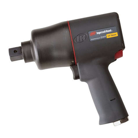
Ingersoll-Rand 772 User manual

Ingersoll-Rand

Ingersoll-Rand 772 User manual

Ingersoll-Rand QA1L High Torque Series User manual

Ingersoll-Rand

Ingersoll-Rand QA1L High Torque Series User manual

Ingersoll-Rand 3103XP User manual

Ingersoll-Rand

Ingersoll-Rand 3103XP User manual

Ingersoll-Rand 1807256 User manual

Ingersoll-Rand

Ingersoll-Rand 1807256 User manual

Ingersoll-Rand PowerForce PF600 User manual

Ingersoll-Rand

Ingersoll-Rand PowerForce PF600 User manual

Ingersoll-Rand 772 User manual

Ingersoll-Rand

Ingersoll-Rand 772 User manual

Ingersoll-Rand 1-EU Series User manual

Ingersoll-Rand

Ingersoll-Rand 1-EU Series User manual

Ingersoll-Rand 125-A User manual

Ingersoll-Rand

Ingersoll-Rand 125-A User manual

Ingersoll-Rand A Series User manual

Ingersoll-Rand

Ingersoll-Rand A Series User manual

Ingersoll-Rand 2141 Setup guide

Ingersoll-Rand

Ingersoll-Rand 2141 Setup guide

Ingersoll-Rand A Series User manual

Ingersoll-Rand

Ingersoll-Rand A Series User manual

Ingersoll-Rand 772 Setup guide

Ingersoll-Rand

Ingersoll-Rand 772 Setup guide

Ingersoll-Rand 2934P2 User manual

Ingersoll-Rand

Ingersoll-Rand 2934P2 User manual

Ingersoll-Rand 121 User manual

Ingersoll-Rand

Ingersoll-Rand 121 User manual

Ingersoll-Rand 2200 Series Setup guide

Ingersoll-Rand

Ingersoll-Rand 2200 Series Setup guide

Ingersoll-Rand AIR HAMMER 114G User manual

Ingersoll-Rand

Ingersoll-Rand AIR HAMMER 114G User manual

Ingersoll-Rand 772 User manual

Ingersoll-Rand

Ingersoll-Rand 772 User manual

Ingersoll-Rand C225H Installation guide

Ingersoll-Rand

Ingersoll-Rand C225H Installation guide

Ingersoll-Rand IR30BV Installation guide

Ingersoll-Rand

Ingersoll-Rand IR30BV Installation guide

Ingersoll-Rand 2DA Series User manual

Ingersoll-Rand

Ingersoll-Rand 2DA Series User manual

Ingersoll-Rand 9001-EU User manual

Ingersoll-Rand

Ingersoll-Rand 9001-EU User manual

Ingersoll-Rand 324 Series User manual

Ingersoll-Rand

Ingersoll-Rand 324 Series User manual

Ingersoll-Rand 327-EU User manual

Ingersoll-Rand

Ingersoll-Rand 327-EU User manual

Ingersoll-Rand PowerForce PF600 User manual

Ingersoll-Rand

Ingersoll-Rand PowerForce PF600 User manual

Popular Tools manuals by other brands

Sealey SG10E instructions

Sealey

Sealey SG10E instructions

jbc FAE020 instruction manual

jbc

jbc FAE020 instruction manual

Valley Industries MHR-M owner's manual

Valley Industries

Valley Industries MHR-M owner's manual

Trax ARX-0123A Operation, maintenance & instruction manual

Trax

Trax ARX-0123A Operation, maintenance & instruction manual

NICOPRESS 5606M instructions

NICOPRESS

NICOPRESS 5606M instructions

Markator FlyMarker PRO Brief instructions

Markator

Markator FlyMarker PRO Brief instructions

SKF PowerLuber 1882E User and maintenance instructions

SKF

SKF PowerLuber 1882E User and maintenance instructions

Neilsen CT4342 Original instructions

Neilsen

Neilsen CT4342 Original instructions

Tyco Electronics 549043-1 operating instructions

Tyco Electronics

Tyco Electronics 549043-1 operating instructions

Rothewald 10018717 Instructions for use

Rothewald

Rothewald 10018717 Instructions for use

Black & Decker BDL190S-XE instruction manual

Black & Decker

Black & Decker BDL190S-XE instruction manual

Bosch GTA 3800 Professional Original instructions

Bosch

Bosch GTA 3800 Professional Original instructions

Ryobi R18TR2 Original instructions

Ryobi

Ryobi R18TR2 Original instructions

DeWalt DCGG570 instruction manual

DeWalt

DeWalt DCGG570 instruction manual

Fumex ASE 130 manual

Fumex

Fumex ASE 130 manual

MSW MSW-HFT-01 user manual

MSW

MSW MSW-HFT-01 user manual

Cherry Aerospace H83B-6MBU Technical data sheet

Cherry Aerospace

Cherry Aerospace H83B-6MBU Technical data sheet

VARO POWERplus XQ POWXQ9100 manual

VARO

VARO POWERplus XQ POWXQ9100 manual

manuals.online logo
manuals.online logoBrands
  • About & Mission
  • Contact us
  • Privacy Policy
  • Terms and Conditions

Copyright 2025 Manuals.Online. All Rights Reserved.