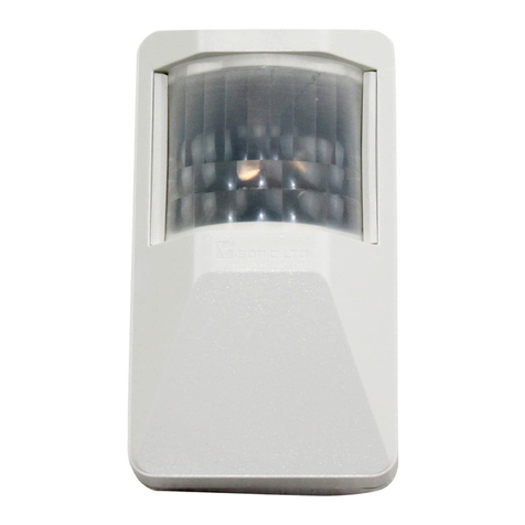
INIM Electronics Air2 Series Assembly instructions

1
Installation and programming manual
Air2-ODI100W
Dual PIR wireless detector
for outdoor use
Installation and programming manual

2
Air2-ODI100W
Table of
contents
1 General information. . . . . . . . . . . . . . . . . . . . . . . . . . . . . 3
1-1 About this manual . . . . . . . . . . . . . . . . . . . . . . . . . . . . . . . . . . . . . . .3
1-2 Manufacturer's details. . . . . . . . . . . . . . . . . . . . . . . . . . . . . . . . . . . . .3
1-3 Description of the product . . . . . . . . . . . . . . . . . . . . . . . . . . . . . . . . . .3
1-4 Package contents . . . . . . . . . . . . . . . . . . . . . . . . . . . . . . . . . . . . . . . .5
2 Functioning. . . . . . . . . . . . . . . . . . . . . . . . . . . . . . . . . . . 5
2-1 Detection range . . . . . . . . . . . . . . . . . . . . . . . . . . . . . . . . . . . . . . . . .5
2-2 Operating principles . . . . . . . . . . . . . . . . . . . . . . . . . . . . . . . . . . . . . .6
2-3 “Test” function. . . . . . . . . . . . . . . . . . . . . . . . . . . . . . . . . . . . . . . . . .7
2-4 “Inhibition” function . . . . . . . . . . . . . . . . . . . . . . . . . . . . . . . . . . . . . .7
3 Installation . . . . . . . . . . . . . . . . . . . . . . . . . . . . . . . . . . . 7
3-1 Placement . . . . . . . . . . . . . . . . . . . . . . . . . . . . . . . . . . . . . . . . . . . . .7
3-2 Mounting. . . . . . . . . . . . . . . . . . . . . . . . . . . . . . . . . . . . . . . . . . . . . .8
4 Programming . . . . . . . . . . . . . . . . . . . . . . . . . . . . . . . . . 9
5 Maintenance and periodic checks . . . . . . . . . . . . . . . . . . . 9
6 Disposal and scrapping . . . . . . . . . . . . . . . . . . . . . . . . . . 9
Appendix 1 declaration of conformity . . . . . . . . . . . . . . . . . . . . . . . . . 10
Appendix 2 Order codes . . . . . . . . . . . . . . . . . . . . . . . . . . . . . . . . . . 11
Copyright
The information contained in this document is the sole property of INIM
Electronics s.r.l. No part may be copied without written authorization
from INIM Electronics s.r.l.
All rights reserved.

General information 3
Installation and programming manual
1
GENERAL INFORMATION
1-1
About this manual
MANUAL CODE
DCMIINIEA2ODI100W
VERSION
1.10
1-2Manufacturer's details
Manufacturer: INIM ELECTRONICS S.R.L.
Production plant: Via Fosso Antico snc - Fraz. Centobuchi
63076, Monteprandone (AP) - Italy
Tel.: +39 0735 705007
Fax: +39 0735 704912
e-mail: [email protected]
Web: www.inim.biz
The persons authorized by the manufacturer to repair or replace the parts of this
system, hold authorization to work on INIM Electronics brand devices only.
1-3Description of the product
• Wireless detector for outdoor use
• Air2 two-way wireless intrusion protection system (868MHz frequency)
• Dual PIR infrared sensors, low consumption and UV filter
• UV resistant Fresnel lens
• Low consumption, power supply range 3 to 9V
• “Test” function to signalling each alarm by LED blinking; auto power off after 4
minutes
• Tamper and dislodgement system
• Inhibition LED and transmitting function for battery life saving (always on)
• AND/OR selectable function
• Mechanism for horizontal coverage adjustment
• Precision adjustment of lower beam (patented)
• Stainless steel pole brackets (not supplied)
• UV resistant polycarbonate casing
Note
The manufacturer cannot guarantee the declared battery life.
Table 1: Air2-ODI100W technical features
Power-supply
from 3 to 9V
Stand-by current
12μA
Maximum current
25mA
Detection range
from 3 to 12m
Horizontal coverage angle
60°
Horizontal coverage adjustment
+/- 45°
IP protection degree
IP44
Working temperature
from -20° to 55°C
Dimensions
189x81x95 mm
Weight (only detector)
450g
Battery
Lithium CR17450 3V (2)
Battery life
4 years

4General information
Air2-OTT100W
I I
Table 2: Mechanical parts description
A
“U” shaped bracket
B
“L” shaped bracket
C
Hermetic casing base
D
Electronic holder
(sensors in front and
transceiver on the back)
E
Cover with Fresnel lens
F
Lower PIR range
adjustment knob
G
Anti tamper microswitch
H
Electronics and sensors
I
“O-ring” gasket
J
Cover enclosure screw
K
Inner screw for “L” and
“U” brackets fixing
L
External screw for “L”
and “U” brackets fixing
M
Base enclosure screw
Table 3: Electronic part description
N
Terminal board for wire connection
O
Red LED for radio transmission
P
Left green LED for each higher PIR
detection
Q
Right green LED for each lower PIR
detection
R
Jumper
S
Higher infrared sensor (PIR 1)
T
Lower infrared sensor (PIR 2)
U
DIP switches
V
Batteries
W
Transmission green LED
X
ENROLL button
A
B
C
D
E
H
A
F
G
I
J
K L
M
M
N
S
T
PQ
R
U
F
Sensors
O
V
X
W
N
Transceiver

Functioning 5
Installation and programming manual
The Air2-ODI100W detector communicates with INIM intrusion control panel via
the Air2 two-way wireless intrusion protection system.
1-4Package contents
Inside the package you will find:
• Air2-ODI100W detector
• Hermetic casing base
• Installing manual (this)
• Plastic bag containing:
•• 6 stainless steel metric screw M3 x 20
•• 4 anchor screws and plugs for wall mounting
•• “O ring” gasket
Items not included in the package (accessory items to be purchased separately;
see Appendix 2, Order codes):
•• “U” shaped brackets
•• “L” shaped brackets
2
FUNCTIONING
2-1
Detection range
ADJUSTMENT
By using the knob (table 2, F) it is possible to move the PIR2 (lower) in order to
obtain different ranges from 3m to 12m.
The knob moves vertically the RIP along the marked positions on the holder. Each
position corresponds to a distance:
Table 4: Technical specifications of Air2 system
Operating frequency range
868.0 - 868.6MHz
selectable channels
868.1, 868.3, 868.5MHz
Communication type
Two-way
Modulation
GFSK
Device supervision
From 12 to 250 minutes
Table 5: Top view
A
Zones that can not be
covered
B
Zones that can be
covered by electronic
holder rotation
150°
60°
15°
15°
B
A
B
A

6Functioning
Air2-OTT100W
These distances are reached when the detector is installed at about 120cm
(height).
2-2Operating principles
The detector operates in the AND mode of PIRs generating an alarm when both
sensors detect a presence.
The figures below shows some of most relevant working examples.
Table 6: Side view
PIR2
position Distance
A
3 m
B
4 m
C
7 m
D
10 m
E
12 m
1.2m
3m 4m 7m 10m 12m
EA
Table 7: Working examples
A
Detector
B
Protected area limit
C
The pet is detected by one of the two sensors (lower PIR).
No alarm
D
The person is detected by all sensors (upper PIR and lower PIR).
Alarm
E
The person is detected by one of the two sensors (upper PIR).
No alarm
F
If the detector is installed on a tilted wall, or pole, the detection range will be
reduced.
Both, upward as downward.
Uncorrected installation
No alarm
D EC B
A
E B
F

Installation 7
Installation and programming manual
2-3“Test” function
This function has been implemeted in order to make the detector easy to set up.
The function can be activated disconnecting and connecting again the jumper
(table 3, R); within a minute the function will be operative. In this mode the LED
will be lighted for each detection. Below the meanings of the LEDs:
•
Red LED
(table 3, O): switch on when there is an alarm or tamper situation.
•
Left green LED
(table 3, P): switch on when the upper PIR detects a motion.
•
Right green LED
(table 3, Q): switch on when the lower PIR detects a motion.
After about 4 minutes the test mode is automatically switched off, and the LED are
deactivated (paragraph 2-4 “Inhibition” function).
Note
Be sure to have screwed up the cover with Fresnel lens before perform the tests.
LEDs activation can be seen through the lens.
Once performed detection and radio transmission range tests, the detector is
ready to work.
Note
LEDs are active only in test mode.
In working mode the LEDs are automatically deactivated. In order to verify if the
detector is working properly, remove the front cover disconnect and connect again
the jumper to activate the testing mode; at the end screw the cover up.
2-4“Inhibition” function
In working mode (LEDs deactivated) the function inhibition is automatically
activated in order to safe battery life. This implies that if the detector has been
installed in a populated area, the detector will no switch the alarm relay if the
detection area is free for three minutes at least.
This function avoid that the detector triggers the alarm relay continuously.
In order to verify if the detector is working properly, wait at least three minutes
after each detection.
3
INSTALLATION
WARNING
It is important to evaluate the installation site previously. Bush close to the
detector might cause false alarm.
The detector is equipped with UV filters in order to avoid problems due to
sunshine rays. Anyway, if it is possible, do not direct the detector versus the sun.
3-1Placement
Start the “test” mode (paragraph 2-3 “Test” function), in order to obtain a real
simulation, keep out the protected area, and avoid any crossing into it.
After 30÷40 seconds without events, come in to the detection area and, looking
the red LED, verify if the detector works correctly.
After the detection, wait at least 7÷8 seconds before the next detection. Refer to
the coverage diagram to estimate the detection area (table 5 "Top view" and table
6 "Side view").
Environmental conditions are important elements to be evaluated during the
installation. Bump, bottomland or slops can modify the performances of the
detector.
If into the detection area any medium size animal can walk, it is suggested to
choose carefully the installation height in order to avoid false alarms.
Note
The maximum coverage range, 12m, is reached when the detector is installed at
about 120cm (height).
Do not obscure partially or completely the detector’s field of view.

8Installation
Air2-OTT100W
3-2Mounting
1. Unscrew the screw for the cover enclosure (table 2, J).
2. Remove the cover with lens (table 2, E).
3. Unscrew the fixing screws (table 2, M) of the detector to the waterproof
rear casing.
4. Fix the hermetic casing (table 2, C) on the wall, or on a pole (be sure the
pole is stable and ripple free).
POLE FIXING
5. Fix the “L” shape bracket (table 2, B) behind the hermetic casing with one
screw (table 2, K).
Note
Use the upper hole to fix the case to the “L” shaped bracket.
6. Position the two “U” (table 2, A) shaped bracket around the pole.
7. Block them with the inner screws (table 2, L) and the external screws (table
2, K).
WALL FIXING
5. Perforate the wall in correspondence of the holes on the casing.
6. Insert the wall plugs into the holes.
7. Screw up the case with the screws. Pay attention to not damage anti tam-
per switch support knock-out.
Note
Use the lower hole to fix the hermetic casing on the wall.
8. Enroll the detector (refer to Air2-BS200 transceiver installation manual).
9. Insert the o-ring gasket (table 2, I) into its seat located on the electronic
holder (table 2, D).
Note
Pay attention to not stretch out the o-ring gasket during its installation.
10. Couple the detector and the hermetic casing then screw (table 2, M).
11. Run the range settings (PIR 2 position adjustment and PIRs sensitivity).
See paragraph 2-1 Detection range.
12. Close the detector with the front cover with Fresnel lens as shown opposite.
13. Screw up the metric screw (table 2, J).

Programming 9
Installation and programming manual
4
PROGRAMMING
In order to make the detector suitable for outdoor applications, a single sensor
adjustment system has been implemented.
In the tables below are shown the DIP switch configurations (table 3, U):
5
MAINTENANCE AND
PERIODIC CHECKS
Keep the lens clean to guarantee proper operation of the detector.
A lens which is not perfectly clean may cause detection problem.
The cleaning must be done when necessary or when clearly dirty.
CLEANING
PROCEDURE
Clean the lid and the lens with a cloth dampened with water.
Wipe with a dry cloth.
ATTENTION!
Do not use chlorine-based or abrasive products or alcohol to remove particularly
noticeable dirt.
6
DISPOSAL AND
SCRAPPING
DISMANTLING
1. Unscrew the screws that fasten the front lid and remove it.
2. Disconnect the detector; disconnect all the terminals on the terminal block.
3. Divide the parts by type and dispose of them in accordance with applicable
laws.
ATTENTION!
Do not dispose of the components or any other product material in the
environment.
Seek the assistance of companies authorised to dispose of and recycle waste
materials.
Table 8: Infrared sensitivity adjustment
OFF ON
DIP 1
PIR 1 sensitivity
LOW PIR 1 sensitivity
HIGH
DIP 2
PIR 2 sensitivity
LOW PIR 2 sensitivity
HIGH

10 declaration of conformity
Air2-OTT100W
Appendix 1
DECLARATION OF
CONFORMITY
Deutsch: Hiermit erklärt INIM Electronics s.r.l., dass sich das Gerät Air2-
ODI100W in Übereinstimmung mit den grundlegenden Anforderungen und den
übrigen einschlägigen Bestimmungen der Richtlinie 1999/5/EG befindet.
ǩȢȓȋȈȘșȒȐ: ǹȕȈșȚȖȧȡȍȚȖ INIM Electronics s.r.l. ȌȍȒȓȈȘȐȘȈ, ȟȍ Air2-ODI100W
ȖȚȋȖȊȈȘȧ ȕȈ șȢȡȍșȚȊȍȕȐȚȍ ȐȏȐșȒȊȈȕȐȧ ȐȌȘțȋȐȚȍ ȗȘȐȓȖȎȐȔȐ ȐȏȐșȒȊȈȕȐȧ ȕȈ
ǬȐȘȍȒȚȐȊȈ 1999/5/ǭǹ.
ƪNJNJdžnjLjljƾ: ƳİǍǎȺNJLjıNjǗǐ ĮǑIJǗǐ ıǑNjNjǎǏijǙnjİIJĮLj Njİ IJdžnj ƪǑǏǔȺĮLjljǀ ƳįdžDŽǁĮ 1999/
5/ƪƮ
Español: Por la presente, el INIM Electronics s.r.l declara que este "producto"
cumple con la requisitos esenciales y otras disposiciones relevantes de la Directiva
1999/5/CE.
Français: Par la présente, INIM Electronics s.r.l. déclare que l’appareil Air2-
ODI100W est conforme aux exigences essentielles et aux autres dispositions
pertinentes de la directive 1999/5/CE.
Dansk: Undertegnede INIM Electronics s.r.l. erklærer herved, at følgende udstyr
Air2-ODI100W overholder de væsentlige krav og øvrige relevante krav i direktiv
1999/5/EF.
Magyar: Ez a berendezés megfelel az európai 1999/5/EC irányelvnek.
Malti: Hawnhekk, INIM Electronics s.r.l., jiddikjara li dan Air2-ODI100W
jikkonforma mal-řtiœijiet essenzjali u ma provvedimenti ořrajn relevanti li hemm
fi d-Dirrettiva 1999/5/EC.
Islenska: Hér með lýsir INIM Electronics yfi r því að Air2-ODI100W er í samræmi
við grunnkröfur og aðrar kröfur, sem gerðar eru í tilskipun 1999/5/EC.
Italiano: Con la presente, INIM Electronics s.r.l. dichiara che questo Air2-
ODI100W è con-forme ai requisiti essenziali ed alle altre disposizioni pertinenti
stabilite dalla direttiva 1999/5/CE.
Lietuviž: Šiuo INIM Electronics s.r.l. deklaruoja, kad šis Air2-ODI100W atitinka
esminius reikalavimus ir kitas 1999/5/EB Direktyvos nuostatas.
English: Hereby, INIM Electronics s.r.l., declares that this Air2-ODI100W is in
compliance with the essential requirements and other relevant provisions of
Directive 1999/5/EC.
Nederlands
: Hierbij verklaart INIM Electronics s.r.l. dat het toestel Air2-ODI100W in
overeenstemming is met de essentiële eisen en de andere relevante bepalingen van
richtlijn 1999/5/EG.
Norsk: INIM Electronics s.r.l. erklærer herved at utstyret Air2-ODI100W er i
samsvar med de grunnleggende krav og øvrige relevante krav I direktiv 1999/5/
EF.
Polski: Niniejszym INIM Electronics s.r.l. deklaruje Īe Air2-ODI100W jest zgodny
z zasadniczymi wymaganiami i innymi wáaĞciwymi postanowieniami Dyrektywy
1999/5/EC.
Português: Eu, INIM Electronics s.r.l., declaro que o Air2-ODI100W cumpre os
requisitos essenciais e outras provisões relevantes da Directiva 1999/5/EC.
Româna: Prin prezenta, INIM Electronics s.r.l., declarăcăaparatul Air2-ODI100W
este în conformitate cu cerinĠele esenĠiale úi cu alte prevederi pertinente ale
Directivei 1999/5/CE.
Svenska: Denna utrustning är i överensstämmelse med de väsentliga kraven och
andra relevanta bestämmelser i Direktiv Försäkran om över 1999/5/EC.
Slovenski: INIM Electronics s.r.l. izjavlja, da je ta Air2-ODI100W v skladu z
bistvenimi zahtevami in drugimi relevantnimi doloþili direktive 1999/5/ES.
The declaration of conformity may be consulted at: www.inim.biz/dc.html

Order codes 11
Installation and programming manual
Appendix 2
ORDER CODES
Please quote the following order codes when ordering items from the INIM
Electronics product range:
DCMIINIEA2ODI100W-R110-20160512
Code Product description
Air2-Aria
Tastiera via radio con display grafico retroilluminato
Air2-BS200/10
Wireless transceiver module, 10 terminals
Air2-BS200/30
Wireless transceiver module, 30 terminals
Air2-BS200/50
Wireless transceiver module, 50 terminals
Air2-DT200T
Wireless dual-technology curtain detector, in white or brown colour
Air2-FD100
Wireless smoke detector
Air2-Hedera-F
Wireless outdoor sounder with anti-foam protection
Air2-Hedera-FM
Wireless outdoor sounder with anti-foam protection, in metal effect enclosure
Air2-IR100
Two-way wireless PIR with 12m coverage
Air2-IR100/C
Two-way wireless PIR with 20m coverage
Air2-KF100
4 button remote-control keyfob
Air2-MC100
Wireless magnetic contact with 2 inputs/outputs, in white or brown colour
Air2-MC200
Two-way wireless magnetic contact, in white or brown colour
Air2-ODI100W
Wireless outdoor double infrared detector
Air2-OTT100W
Wireless outdoor triple-technology detector
Air2-UT100
Universal wireless transceiver
Air2-XDT200W
Double technology wireless detector
Air2-XIR200W
Infrared wireless detector
DCMIINI0A2BS200E
Air2 devices installation manual
DCMIINIEA2ODI100W
Air2-ODI100W installation and programming manual
OTTBK200
Inox mounting bracket kit, 2 “U” shaped brackets and 1 “L”-shaped bracket
OTTCV100
Weather proof cover
SmartLiving10100L
Intrusion control panel: manages 10 to 100 terminals, 15 partitions, switching power supply
@5A, optional TCP/IP connectivity, comes in metal enclosure with housing for 1 battery @17Ah
SmartLiving10100L/G3
Intrusion control panel: manages 10 to 100 terminals, 15 partitions, switching power supply
@5A, optional TCP/IP connectivity, comes in metal enclosure with housing for 1 battery @17Ah.
EN50131-6 grade 3 certified.
SmartLiving1050
Intrusion control panel: manages 10 to 50 terminals, 10 partitions, switching power supply
@3A, comes in metal enclosure with housing for 1 battery @ 7 or 9Ah
SmartLiving1050/G3
Intrusion control panel: manages 10 to 50 terminals, 10 partitions, switching power supply
@3A, comes in metal enclosure with housing for 1 battery @ 7 or 9Ah. EN50131-6 grade 3
certified.
SmartLiving1050L
Intrusion control panel: manages 10 to 50 terminals, 10 partitions, switching power supply
@3A, optional TCP/IP connectivity, comes in metal enclosure with housing for 1 battery @17Ah
SmartLiving1050L/G3
Intrusion control panel: manages 10 to 50 terminals, 10 partitions, switching power supply
@3A, optional TCP/IP connectivity, comes in metal enclosure with housing for 1 battery @17Ah.
EN50131-6 grade 3 certified.
SmartLiving505
Intrusion control panel: manages 5 terminals, 5 partitions, switching power supply @ 1.2A,
comes in metal enclosure with housing for 1 battery @7 or 9Ah
SmartLiving515
Intrusion control panel: manages 5 to 10 terminals, 5 partitions, switching power supply @
1.2A, comes in metal enclosure with housing for 1 battery @7 or 9Ah

14
Air2-ODI100W
via Fosso Antico snc - fraz. Centobuchi
63076 Monteprandone (AP) ITALY
Tel. +39 0735 705007 _ Fax +39 0735 704912
ISO 9001 Quality Management
certified by BSI with certificate number FM530352
Other manuals for Air2 Series
3
This manual suits for next models
2
Table of contents
Other INIM Electronics Security Sensor manuals
INIM Electronics
INIM Electronics ID100 User manual
INIM Electronics
INIM Electronics Moon 700 Series User manual
INIM Electronics
INIM Electronics ODI100H Assembly instructions
INIM Electronics
INIM Electronics OTT100H Assembly instructions
INIM Electronics
INIM Electronics EB0020 User manual
INIM Electronics
INIM Electronics ED100 Technical specifications
INIM Electronics
INIM Electronics Air2-OTT100W Assembly instructions
INIM Electronics
INIM Electronics Air2 Series Assembly instructions
