Inogen One G3HF User manual

96-06434-00-01 revA
Service Manual, Inogen One G3HF
-2-
TABLE OF
CONTENTS
SP-502 and SP-550 Inogen One G3HF Front and Rear Housing Replacement..............................3
SP-503 Inogen One G3 User Interface Panel Replacement ............................................................6
SP-504 Inogen One G3 LCD Replacement...................................................................................11
SP-560 Inogen One G3HF Top Column Receptacle Replacement...............................................16
SP-561 and SP 562 Inogen One G3HF Molded Column Tubes ...................................................21
SP-551 Inogen One G3 Inlet Tube Replacement ..........................................................................27
SP-552 Inogen One G3 Exhaust Tube Replacement.....................................................................32
SP-507 Inogen One G3 Filter Box Lid Replacement....................................................................38
SP-553 Inogen One G3HF Fan
Replacement
................................................................................40
SP-509 Inogen One G3 CompressorReplacement........................................................................46
SP-554 Inogen One G3HF Power Cable Replacement .................................................................54
SP-555 Inogen One G3HF Product Manifold Replacement..........................................................59
SP-556 Inogen One G3HF Feed Waste Manifold Replacement ...................................................66
SP-513 Inogen One G3 Accumulator Replacement......................................................................73
SP-514 Inogen One G3 Breath Detect Sensor Replacement.........................................................82
SP-557 Inogen One G3HF Motherboard Replacement.................................................................90
SP-516 Inogen One G3 Filter Body Replacement.........................................................................97
SP-558 Inogen One G3HF Tube Bracket and Muffler Replacement..........................................102
SP-519 Inogen One G3 LCD Cable Replacement.......................................................................105
SP-520 Inogen One G3 Dual Feed Tube Replacement ...............................................................109
SP-521 Inogen One G3 Column Latch Replacement..................................................................115
SP-522 Inogen One G3 Column Receptacle Replacement .........................................................120
SP-523 Inogen One G3F Chassis Replacement ..........................................................................125

96-06434-00-01 revA
Service Manual, Inogen One G3HF
-3-
SP-502 and SP-550 Inogen One G3HF Front and Rear Housing
Replacement
Parts Required:
1. SP-502, Housing, Rear
2. SP-550, G3HF Housing, Front
Tools Required:
1. T10 Torx Driver
Notes:
1. When removing screws from the device, carefully set in a bin or secure area as these
screws will used to secure the replacement parts.
2. Many of the screws used on the Inogen One G3 have pre-applied loctite on the threads.
These loctite screws can be re-used up to four times before replacement screws are
required (If exceeded four uses please contact Inogen for a screw replacement kit).
Instructions for Removing the Housing:
1. While facing the front housing, remove the battery from the concentrator by pushing
down on the blue battery release clip and sliding the device away (Figure 1).
Figure 1: Direction to slide device to remove battery

96-06434-00-01 revA
Service Manual, Inogen One G3HF
-4-
2. To remove the back housing, place the device on its front side and remove the two screws
that secure the back housing to the chassis (Figure 2).
Figure 2: Location of screws
3. With the concentrator still on its front side, slide the back housing down and away from
the device then lift up to remove (Figure 3).
Figure 3: Direction to slide housing
4. To remove the front housing, place the device on its back side and remove the two screws
that secure the front housing to the chassis (Figure 4).

96-06434-00-01 revA
Service Manual, Inogen One G3HF
-5-
Figure 4: Location of screws
5. Slide the front housing down and away from the device then lift up to remove.
Instructions for Replacing the Housing:
1. Place the device on its back side.
2. Seat the feet of the front housing into the corresponding grooves on the chassis (Figure 5)
then push down and toward the device to secure the housing in the chassis.
Figure 5: Housing feet and corresponding chassis grooves
3. Place the device on its front side and repeat step 2 to secure the back housing into the
chassis.
4. Replace the two screws that connect the back housing to the chassis and the two screws
that connect the front housing to the chassis (Figures 2 and 4). Tighten to 3 in-lbs.
5. Return the concentrator to the upright position
6. Slide the battery back into the chassis. Ensure the battery clip is fully seated.

96-06434-00-01 revA
Service Manual, Inogen One G3HF
-6-
SP-503 Inogen One G3 User Interface Panel Replacement
Parts Required:
1. SP-503, User Interface Panel
Tools Required:
1. T10 Torx Driver
Notes:
1. When removing screws from the device, carefully set in a bin or secure area as these
screws will be used to secure the replacement parts.
2. Many of the screws used on the Inogen One G3 have pre-applied loctite on the threads.
These loctite screws can be re-used up to four times before replacement screws are
required (If exceeded four uses please contact Inogen for a screw replacement kit).
3. The connectors for the LCD and User Interface Panel are delicate and should be handled
carefully. They must be inserted into the connector straight and be clean of all debris or
contamination in order to ensure proper LCD and User Interface Panel Operation.
Instructions for Removing the Housing:
Refer to “SP-502 and SP-550 Inogen One G3HF Front and Rear
Housing
Replacement
”
on Page 3. Follow steps 1-5 for “Instructions for Removing the Housing.”
Instructions for Removing the User Interface Panel:
1. With the side housing removed, locate and remove the four screws that connect the user
interface panel to the chassis (Figures 1 and 2).
Figure 1: Location of rear screws

96-06434-00-01 revA
Service Manual, Inogen One G3HF
-7-
Figure 2: Location of front screws
2. Gently pull upward on the user interface panel to lift it about a centimeter off the device,
being careful not to pull on the cables that are connected to the user interface panel. With
the UIP cable connector exposed on the motherboard, gently unplug the UIP cable from
the motherboard (Figure 3).
Figure 3: Unplug UIP cable from motherboard

96-06434-00-01 revA
Service Manual, Inogen One G3HF
-8-
3. Gently unplug the cannula tube and the LCD cable from the user interface panel (Figure
4). Remove the user interface panel.
Figure 4: Remove cannula tube and LCD cable from user interface panel
Instructions for Replacing the User Interface Panel:
1. Lay the user interface panel upside down with the underside of the LCD facing upward.
Remove the two screws securing the LCD to the user interface panel (Figure 5).
Figure 5: Location of LCD screws
Cannula Tube
LCD Cable

96-06434-00-01 revA
Service Manual, Inogen One G3HF
-9-
2. Place the LCD module against the back side of the UIP window on the new user interface
panel. Orient the LCD module so that the LCD cable connector is on the right side of the
user interface panel (as in Figure 5).
3. Re-install the two screws securing the LCD to the user interface panel, making sure that
the LCD is straight and properly aligned in the UIP window (Figure 5). Tighten screws to
5 in-lbs.
4. Reconnect the power cable to the LCD module (Figure 6). Note the location of the red
wire.
Figure 6: Orientation of LCD cable
5. Re-attach the cannula tubing to the cannula connector (Figure 4).
6. Plug the UIP cable back into the motherboard (Figure 3). Double check that the cables
are fully seated to ensure a complete connection.
7. Test the function of each button and the LCD. If anything does not work, reseat the
cables in the connectors and check for debris in the connectors.
8. Re-install the four screws that connect the user interface panel to the chassis (Figures 1
and 2). Tighten screws to 5 in-lbs.
Instructions for Replacing the Housing:
1. Place the device on its back side.
2. Seat the feet of the front housing into the corresponding grooves on the chassis (Figure
7) then push down and toward the device to secure the housing in the chassis.

96-06434-00-01 revA
Service Manual, Inogen One G3HF
-10-
Figure 7: Housing feet and corresponding chassis grooves
3. Place the device on its front side and repeat step 2 to secure the back housing into the
chassis.
4. Replace the two screws that connect the back housing to the chassis and the two screws
that connect the front housing to the chassis. Tighten screws to 3 in-lbs.
5. Return the concentrator to the upright position.
6. Slide the battery back into the chassis. Ensure the battery clip is fully seated.

96-06434-00-01 revA
Service Manual, Inogen One G3HF
-11-
SP-504 Inogen One G3 LCD Replacement
Parts Required:
1. SP-504, LCD
Tools Required:
1. T10 Torx Driver
Notes:
1. When removing screws from the device carefully set in a bin or secure area as these
screws will used to secure the replacement parts.
2. Many of the screws using on the Inogen One G3 have pre-applied loctite on the threads.
These loctite screws can be re-used up to four times before replacement screws are
required (If exceeded four uses please contact Inogen for a screw replacement kit).
3. The connectors for the LCD and User Interface Panel are delicate and should be handled
carefully. They must be inserted into the connector straight and be clean of all debris or
contamination in order to ensure proper LCD and User Interface Panel Operation.
Instructions for Removing the Housing:
Refer to “SP-502 and SP-550 Inogen One G3HF Front and Rear
Housing
Replacement
”
on Page 3. Follow steps 1-5 for “Instructions for Removing the Housing.”
Instructions for Removing the User Interface Panel:
1. With the side housing removed, locate and remove the four screws that connect the user
interface panel to the chassis (Figures 1 and 2).
Figure 1: Location of rear screws

96-06434-00-01 revA
Service Manual, Inogen One G3HF
-12-
Figure 2: Location of front screws
2. Gently pull upward on the user interface panel to lift it about a centimeter off the device,
being careful not to pull on the cables that are connected to the user interface panel. With
the UIP cable connector exposed on the motherboard, gently unplug the UIP cable from
the motherboard (Figure 3).
Figure 3: Unplug UIP cable from motherboard

96-06434-00-01 revA
Service Manual, Inogen One G3HF
-13-
3. Gently unplug the cannula tube and the LCD cable from the user interface panel (Figure
4). Remove the user interface panel.
Figure 4: Remove cannula tube and LCD cable from user interface panel
4. Lay the user interface panel upside down with the underside of the LCD facing upward.
Remove the two screws securing the LCD to the user interface panel and remove the
LCD (Figure 5).
Figure 5: Location of LCD screw
Cannula Tube
LCD Cable

96-06434-00-01 revA
Service Manual, Inogen One G3HF
-14-
Instructions for Replacing the LCD:
1. Place the new LCD module against the back side of the UIP window on the user interface
panel. Orient the LCD module so that the power cable connector on the LCD is on the
right side of the user interface panel (as shown in Figure 5).
2. Re-install the two screws securing the LCD to the user interface panel, making sure that
the LCD is straight and properly aligned in the UIP window (Figure 5). Tighten screws to
5 in-lbs.
3. Reconnect the cable to the LCD module (Figure 6).
Note the location of the red wire.
Figure 6: Orientation of LCD cable
4. Re-attach the cannula tubing to the cannula connector (Figure 4).
5. Plug the UIP cable back into the motherboard (Figure 3). Double check that the cables
are fully seated to ensure a complete connection.
6. Test the function of each button and the LCD. If anything does not work, reseat the
cables in the connectors and check for debris in the connectors.
7. Re-install the four screws that connect the user interface panel to the chassis (Figures 1
and 2). Tighten screws to 5 in-lbs.

96-06434-00-01 revA
Service Manual, Inogen One G3HF
-15-
Instructions for Replacing the Housing:
1. Place the device on its back side.
2. Seat the feet of the front housing into the corresponding grooves on the chassis (Figure
7) then push down and toward the device to secure the housing in the chassis.
Figure 7: Housing feet and corresponding chassis grooves
3. Place the device on its front side and repeat step 2 to secure the back housing into the
chassis.
4. Replace the two screws that connect the back housing to the chassis and the two screws
that connect the front housing to the chassis. Tighten screws to 3 in-lbs.
5. Return the concentrator to the upright position.
6. Slide the battery back into the chassis. Ensure the battery clip is fully seated.

96-06434-00-01 revA
Service Manual, Inogen One G3HF
-16-
SP-560 Inogen One G3HF Top Column Receptacle Replacement
Parts Required:
1. SP-560, Column Receptacle, Top, G3HF
Tools Required:
1. T10 Torx Driver
Notes:
1. When removing screws from the device carefully set in a bin or secure area as these
screws will used to secure the replacement parts.
2. Many of the screws using on the Inogen One G3 have pre-applied loctite on the threads.
These loctite screws can be re-used up to four times before replacement screws are
required (If exceeded four uses please contact Inogen for a screw replacement kit).
3. The connectors for the LCD and User Interface Panel are delicate and should be handled
carefully. They must be inserted into the connector straight and be clean of all debris or
contamination in order to ensure proper LCD and User Interface Panel Operation.
Instructions for Removing the Housing:
Refer to “SP-502 and SP-550 Inogen One G3HF Front and Rear
Housing
Replacement
”
on Page 3. Follow steps 1-5 for “Instructions for Removing the Housing.”
Instructions for Removing the User Interface Panel:
1. With the side housing removed, locate and remove the four screws that connect the user
interface panel to the chassis (Figures 1 and 2).
Figure 1: Location of rear screws

96-06434-00-01 revA
Service Manual, Inogen One G3HF
-17-
Figure 2: Location of front screws
2. Gently pull upward on the user interface panel to lift it about a centimeter off the device,
being careful not to pull on the cables that are connected to the user interface panel. With
the UIP cable connector exposed on the motherboard, gently unplug the UIP cable from
the motherboard (Figure 3).
Figure 3: Unplug UIP cable from motherboard

96-06434-00-01 revA
Service Manual, Inogen One G3HF
-18-
3. Gently unplug the cannula tube and the LCD cable from the user interface panel (Figure
4). Remove the user interface panel.
Figure 4: Remove cannula tube and LCD cable from user interface panel
4. Remove the two screws from the receptacle that needs replacing (Figure 5).
Figure 5: Column Receptacle Screws
5. Remove the receptacle from the molded column tube using a small flathead screw driver, if
necessary.
Instructions for Replacing the Column Receptacles:
1. Install the column receptacle into the molded column tube, ensuring that the clocking lines
on the tube are directly on top of the receptacle barb (Figure 6). Place the receptacle on top
of the column.
Cannula Tube
LCD Cable

96-06434-00-01 revA
Service Manual, Inogen One G3HF
-19-
Figure 6: Column Receptacle and Tubing
2. Reinstall the two screws on the column receptacle (Figure 5). Torque to 3 in-lbs.
Instructions for Replacing the Housing:
1. With the new receptacles installed, the user interface panel can now be replaced. Plug the
LCD cable back into the motherboard (Figure 4). Note orientation of red wire. Re-attach
the cannula tubing to the cannula connector.
2. Reconnect the UIP cable to the motherboard (Figure 3).
3. Test the function of each button and the LCD. If anything does not work, reseat the
cables in the connectors and check for debris in the connectors.
4. Re-install the four screws that connect the user interface panel to the chassis (Figures 1
and 2). Tighten screws to 5 in-lbs.
5. Place the device on its back side.
6. Seat the feet of the front housing into the corresponding grooves on the chassis (Figure
9) then push down and toward the device to secure the housing in the chassis.

96-06434-00-01 revA
Service Manual, Inogen One G3HF
-20-
Figure 9: Housing feet and corresponding chassis grooves
7. Place the device on its front side and repeat step 6 to secure the back housing into the
chassis.
8. Replace the two screws that connect the back housing to the chassis and the two screws
that connect the front housing to the chassis. Tighten screws to 3 in-lbs.
9. Return the concentrator to the upright position.
10. Slide the battery back into the chassis. Ensure the battery clip is fully seated.
Table of contents
Other Inogen Medical Equipment manuals
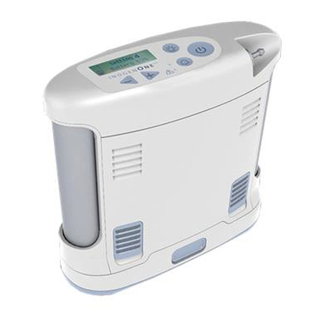
Inogen
Inogen One G3 Technical Document
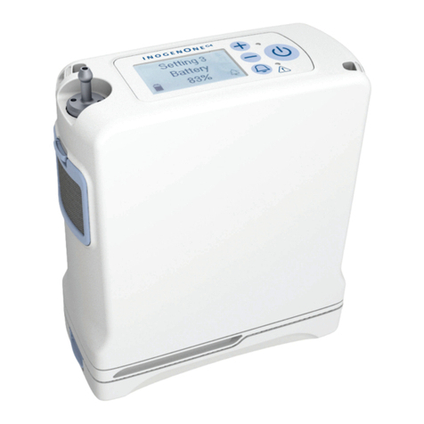
Inogen
Inogen One G4 User manual

Inogen
Inogen One G3 User manual
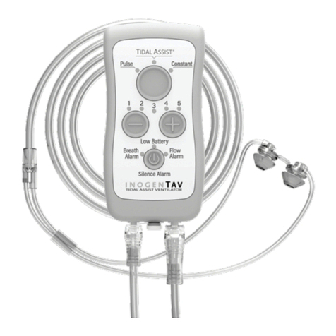
Inogen
Inogen TIDAL ASSIST User manual
Inogen
Inogen InogenOne G4 User manual
Inogen
Inogen Rove 6 User manual

Inogen
Inogen One G3 User manual

Inogen
Inogen One G3 User manual
Inogen
Inogen One G5 User manual
Inogen
Inogen IO-100 User manual

Inogen
Inogen One G3 User manual
Inogen
Inogen TAV User manual

Inogen
Inogen One G3 User manual

Inogen
Inogen One G5 User manual
Inogen
Inogen at home User manual
Inogen
Inogen One G2 User manual

Inogen
Inogen One G4 User manual

Inogen
Inogen One G3 User manual

Inogen
Inogen at home User manual

Inogen
Inogen One G4 User manual


