Inoxtrend GCA-304E2 User manual

EN CONVECTION OVENS
INSTRUCTIONS FOR THE INSTALLATION, USE AND MAINTENANCE
IT FORNI A CONVEZIONE
ISTRUZIONI PER L’INSTALLAZIONE, L’USO E LA MANUTENZIONE
DE HEISSLUFTÖFEN
ANLEITUNGEN FÜR DEN INSTALLATEUR, BEDIENUNGS-UND WARTUNG
FR FOURS À AIR PULSE’
INSTRUCTIONS POUR L’INSTALLATION, L’EMPLOI ET LA MAINTENANCE
ES HORNOS A CONVECCIÓN
INSTRUCCIONES PARA LA INSTALACIÓN, USO Y MANTENIMIENTO
NL CONVECTIEOVENS
INSTRUCTIES VOOR DE INSTALLATIE, GEBRUIK EN ONDERHOUD
B02.0003.00
SN-CA-304E SN-SA-304E
SN-CA-404E SN-SA-404E
SN-CA-304EW SN-CA-604E
SN-CA-404EW SN-UA-604E
SN-CA-304EWS SN-UA-004E
SN-CA-404EWS SN-UA-604EW
SN-UA-304E SN-UA-004EW
SN-UA-404E SN-UA-604ES
SN-UA-304EW SN-UA-004ES
SN-UA-404EW SN-SA-604E
SN-UA-304EWS SN-SA-004E
SN-UA-404EWS
ER304-CAE
ER304-CAEP
ER404-CAE
ER404-CAEP
ER304-CSAE
ER404-CSAE
ER004-UAE
ER004-UAEP
ER004-USAE
FM443
FM423
FM443S
FM461
FM461S
2200740
2200741
GCA-304E2 GUA-304ES
GCA-404E2 GUA-404ES
GCA-304E GUA-604E
GCA-404E GUA-004E
GCA-304ES GUA-604ES
GCA-404ES GUA-004ES
GUA-304E GUA-604EW
GUA-404E GUA-004EW
BRIO43/X-P
BRIO43S/X-P
BRIO64/X-P
GASTRO23/X-P

EN INDEX IT INDICE DE INHALT
Dimensions Dimensioni Abmessungen
Foreword Premessa Vorwort
1.0 Declaration of Conformity Dichiarazione di conformità Konformitätserklärung
1.1 European Directive
ROHS 2012/19/UE Direttiva Europea
ROHS 2012/19/UE Europäische Richtlinie
ROHS 2012/19/UE
1.3 Transport of the oven and
packaging removal Trasporto del forno e rimozione
degli imballi Transport des Ofens und
Entfernung der Verpackung
1.4 Informative labels Targhette informative Informationsetiketten
INSTALLATION INSTALLAZIONE INSTALLATION
1.5 Oven positioning Posizionamento del forno Positionierung des Ofens
1.6 Electrical connection Collegamento elettrico Elektroanschluss
1.7 Technical data for electrical
connection Tabella dati tecnici allacciamento
elettrico Tabelle technische Daten Elektro-
anschluß
2.5 Hydraulic connection
water inlet Collegamento idraulico
entrata acqua Anschluss ans Wassernetz
Wasserzufuhr
3.1 Spare parts replacing Sostituzione parti di ricambio Austausch der ersatzteile
3.2 Checking the functions Controllo delle funzioni Kontrolle der funktionen
USE AND MAINTENANCE USO E MANUTENZIONE BEDIENUNGS-UND WARTUN-
GSANLEITUNG
4.0 Description of the control panel
components Descrizione componenti pannello
comandi Programmierung und Betrieb
4.5 Starting the oven Avviamento del forno Steuerung und
Kontrollvorrichtungen
4.6 Turning the oven o Spegnimento del forno Ausschalten des Gerätes
9.0 Maintenance Manutenzione Wartung
9.1 What to do in the case of a brea-
kdown or non use Comportamento in caso di guasto
e/o prolungato inutilizzo
Anweisungen bei Störungen und/
oder längerem
Gerätestillstand
10.1 Remedies to cooking hitches Rimedi alle anomalie di cottura Abhilfe bei anormalem Garen
FR INDEX ES INDICE NL INHOUDSOPGAVE
Dimensions Dimensiones Afmetingen
Avant-propos Premisa Introductie
1.0 Déclaration de conformité Declaración de conformidad Verklaring van conformiteit
1.1 Directive européenne
ROHS 2012/19/UE Directiva Europea
ROHS 2012/19/UE Europese Richtlijn
ROHS 2012/19/UE
1.3 Transport du four et élimination
de l’emballage Transporte del horno y remoción
de los embalajes Transport van de oven en verwij-
deren van de verpakking
1.4 Etiquettes informatives Tarjetas informativas Informatieve etiketten
INSTALLATION INSTALACIÓN INSTALLATIE
1.5 Positionnement du four Posicionamiento del horno Het plaatsen van de oven
1.6 Raccordement électrique Conexión eléctrica Elektrische aansluiting
1.7 Tableau des données techniques
raccordement électrique Tabla datos técnicos de
conexión eléctrica Tabel technische
gegevens - elektrische
aansluiting
2.5 Raccordement hydraulique - arri-
vée d’eau Conexión hídrica-entrada del
agua Wateraansluiting – waterinlaat
3.1 Remplacement des pièces Piezas de recambio Vervanging reserveonderdelen
3.2 Contrôle des fonctions Control de las funciones Controle van de functies
EMPLOI ET MAINTENANCE USO Y MANTENIMIENTO GEBRUIK EN ONDERHOUD
4.0 Description des éléments du
panneau Descripción componentes panel
de mandos Beschrijving van componenten
bedieningspaneel
4.5 Commandes et contrôles auxi-
liaires Encendido del horno Starten de oven
4.6 Arrêt du four Apagado del horno Het uitschakelen van de oven
9.0 Maintenance Mantenimento Onderhoud
9.1 Que faire en cas de panne ou
d’arrêt prolongé de l’appareil Comportamiento en caso de
avería o de larga inactividad Handelen in geval van
storingen
10.1 Que faire pour résoudre les pro-
blèmes de cuisson Remedios para las anomalías de
cocción Oplossingen voor problemen bij
het koken
2

A
D
B
48 30
33
293
63 50
23 547
570
8147
23
404
641
78
50
BA
D
435
593
409 8989
587
563
641
4 x 2/3 GN - 4 x 460x340
Dimensioni Capacità Distanza teglie Peso a vuoto
Dimensions Capacity Trays distance Empty weight
Abmessungen Kapazität Einschubabstand Leergewicht
Dimensions Capacité Ecartement grilles Poids à vide
Dimensiones Capacidad Distancia bandejas Peso en vacío
Afmetingen Capaciteit Afstand dienbladen Leeggewicht
mm 587 x 610 x h 565 4 x 2/3 GN
4 x 460x340 70 mm 40 kg
3

A
D
B
620
48
698
30
33
362
63 50
58 547
605
8854988
725
8149247
23
404
698
650
78
50
BA
D
4 x 60x40
Dimensioni Capacità Distanza teglie Peso a vuoto
Dimensions Capacity Trays distance Empty weight
Abmessungen Kapazität Einschubabstand Leergewicht
Dimensions Capacité Ecartement grilles Poids à vide
Dimensiones Capacidad Distancia bandejas Peso en vacío
Afmetingen Capaciteit Afstand dienbladen Leeggewicht
mm 725 x 677 x h 600 4 x 60x40 70 mm 52 kg
4

5
FOREWORD
The contents of this manual are generic and not all the functions described may be available on your
product.
The manufacturer declines all responsibility for possible inaccuracies contained in this pamphlet, due to printing
or copy errors. We reserve the right to make on our own products those changes to be considered necessary or
useful, without jeopardizing the essential characteristics.
Read the instructions for use very carefully paying particular attention to the rules concerning safety devices. This
appliance must only be used for what it has been designed for and built for and that is: all baking of dishes and
regenerating pre-cooked and/or frozen food.
WARNING!
Before making any type of connection of this equipment (electrical or hydraulic), carefully read the instructions
in this manual. This manual must be carefully kept to be available for future reference by users or service tech-
nicians. Installation must be carried out by d qualied personnel only.
1.0 DECLARATION OF CONFORMITY
The Manufacturer declares that the appliances conform to the EEC norms.
They must be installed in accordance with current standards, especially regarding aeration of the premises and
the exhaust gas evacuation system.
Note: The Manufacturer declines all and every responsibility for any direct damages caused by: an
incorrect use, wrong installation or bad maintenance.
1.1 EUROPEAN DIRECTIVE ROHS 2012/19/UE
This appliance is marked according to the European directive 2012/19/UE on Waste Electrical and Electronic
Equipment (WEEE). By ensuring this product is disposed correctly, you will help prevent potential negative con-
sequences for the environment and human health, which could otherwise be caused by inappropriate waste han-
dling of this product.
The symbol on the product, or on the documents accompanying the product, indicates that this
appliance may not be treated as household waste.
Instead it shall be handed over to the applicable collection point for the recycling of electrical
and electronic equipment.
Disposal must be carried out in accordance with local environmental regulations for waste dis-
posal.
1.3 TRANSPORT OF THE OVEN AND PACKAGING REMOVAL
Upon receipt of the oven and before installing it, check the packaging is intact and there are not visible damages.
Also check that along with the oven you receive also the documentation, consisting of:
• Instructions for installation, use and maintenance
• Chart to check correct installation
• Wiring diagram
• Label ISO 3864-1
Before bringing the oven to the point, where it must be installed, check the following:
The doors are large enough to allow passage of the oven
The oor supports the weight.
According to the model of oven, its dimensions and its weight, use suitable facilities to handle goods during trans-
port and installation, able to guarantee stability in order to avoid overturning, falls or uncontrolled movements of
the appliance or its components.
Keep the oven packed until you reach the site where the oven is going to be installed.
The packaging makes the handling of goods easier and protects the oven from accidental push.
During moving and installation of the oven, the installer must comply with accident-prevention regulations in
force at the place of installation (use of safety shoes, gloves, etc.) Remove the packaging taking care not to dam-
age the oven. The adhesive lm, that protects the surfaces made of stainless steel can be removed also after you
have positioned the oven on the corresponding stand or the support surface.
ATTENTION: Packaging materials and adhesive lm are potentially dangerous.
For this reason, they must be kept out of the reach of children and properly disposed of in com-
pliance with local directives.
You should separate packaging materials (wood, cardboard, plastic...) and dispose of them se-
parately, in compliance with directives in force at installation site.
Note: Take the protective lm o the stainless steel parts by hand before starting the appliance.
Do not use abrasive substances and/or metal objects. Clear any adhesive residues using a sponge soaked in sol-
vent. If the oven is heated up before removing the adhesive lm, the removal of the lm and cleaning of residues
of glue will be much more dicult.
EN

6
1.4 INFORMATIVE LABELS
On each oven there are applied some metal labels, that give important info concerning characteristics of the oven,
electric and plumbing connections and eventually the drain connection.
On the right hand side panel there is the label A.
The info contained on this label are:
• Name and address of the manufacturer
• Oven model
• IPX protection grade against water jet.
• Conformity to EC directives.
• Power input and power supply (single or three phase).
• Serial number of the oven
• Symbol of European Directive 2012/19/UE
Removing the back side panel, on the oven chassis you nd label B.
On this label the serial number of the oven is repeated.
In this way, the customer or the installer can nd the serial number of the
oven also when the label A is dirty or damaged.
If the oven is equipped with humidication, in the back of the oven, near the
connector for water connection there is the label C.
Label C indicates water features necessary for a correct functioning of the
oven.
Same features are listed at paragraph 2.3A of this manual.
INSTALLATION
1.5 POSITIONING OF THE OVEN
The place where the oven will be installed must comply the following requirements:
• Be protected from atmospheric agents and have an adequate air circulation;
• Comply with regulations concerning safety at work;
• Have a room temperature between 5 °C and 35 °C with a humidication not higher than 70%.
• Place the oven and proceed with levelling using adjustable feet.
•
Keep a suitable distance at the back, in order the label of equipotential clamp is easy to see when the oven has
been installed. The same clamp must be easy to access to install equipotential cable after the oven has been
installed in compliance with our instructions.
Install the appliance in a position that allows access to the right side for installation, maintenance and technical
assistance.
1.6 ELECTRICAL CONNECTION
When the appliance is delivered it is set to work at the voltage given on the rating plate axed on the right side
of the appliance.
The eectiveness of the equipotential system of which the appliance is part of, must conform to current stand-
ards.
Connect using the screw you nd in the back side of the oven, marked with the word EQUIPOTENTIAL.
The Manufacturer declines all and every responsibility if this important accident prevention norm is not complied
with. If the feeding cable is damaged, it must be replaced by the technical service or in any case by similar qual-
ied personnel, in order to avoid any risk.
EN

7
EN
1.7 TECHNICAL DATA FOR ELECTRICAL CONNECTION
Model Power loading
and voltage no. and motor
power Heating
power Grill
power Absorbed
current
4 x 2/3 GN
4 x 460x340
convection
2.7 kW
220-240 V 1N ~
50/60 Hz 1 x 55 W 2.65 kW -- 11.7 A
4 x 2/3 GN
4 x 460x340
humidication
2.7 kW
220-240 V 1N ~
50/60 Hz 1 x 55 W 2.65 kW -- 11.7 A
4 x 2/3 GN
4 x 460x340
convection
powered
3.2 kW
220-240 V 1N ~
50/60 Hz 2 x 55 W 3.1 kW -- 13.5 A
4 x 2/3 GN
4 x 460x340
humidication
powered
3.2 kW
220-240 V 1N ~
50/60 Hz 2 x 55 W 3.1 kW -- 13.5 A
4 x 2/3 GN
4 x 460x340
convection
powered grill
3.6 kW
220-240 V 1N ~
50/60 Hz 2 x 55 W 2.8 kW 0.7 kW 15.6 A
4 x 2/3 GN
4 x 460x340
humidication
powered grill
3.6 kW
220-240 V 1N ~
50/60 Hz 2 x 55 W 2.8 kW 0.7 kW 15.6 A
4 x 2/3 GN
4 x 460x340
with steam
3.3 kW
220-240 V 1N ~
50/60 Hz 1 x 240 W 3.0 kW -- 14.6 A
4 x 60x40
convection
5.8 kW
380–415 V 3N ~
50/60 Hz
1 x 240 W 5.5 kW -- 15.4 A
4 x 60x40
4 x 1/1 GN
humidication
3.2 kW
220-240 V 1N ~
50/60 Hz 2 x 55 W 3.1 kW -- 13.5 A
4 x 60x40
4 x 1/1 GN
humidication
powered
4.9 kW
380–415 V 3N ~
50/60 Hz
2 x 55 W 4.8 kW -- 13.5 A
4 x 60x40
4 x 1/1 GN
humidication
grill
3.6 kW
220-240 V 1N ~
50/60 Hz 2 x 55 W 2.8 kW 0.7 kW 15.6 A
4 x 60x40
4 x 1/1 GN
with steam
5.8 kW
380–415 V 3N ~
50/60 Hz
1 x 240 W 5.5 kW -- 15.4 A
Single phase ovens are supplied with electric power cable, three phases needs 5x1,5 mm2 cable.

8
2.5 HYDRAULIC CONNECTION – WATER INLET
If the humidication system is installed, the ovens have a water inlet coupling at the back.
Always install an on-o valve between the appliance and the water mains, making sure it is easy to operate.
We also suggest installing a cartridge lter on the water inlet pipe.
Always use a set of new water joints, eventual old joints must not be used again.
Plumbing connection must be always eected with cold water and rigid pipes.
Never use hoses to connect the oven to the water main.
The water must be suitable to human use with the following characteristics:
Temperature: included between 15 – 20°C
Total hardness: included between 4 and 12 °f (French degrees), it is advisable to install a softener upstream
from the appliance that will maintain the hardness level at the mentioned values.
Pressure: included between 150 and 250 KPa (1,5 – 2,5 bar).
Attention: higher water pressure values result in increased water consumption and can compromise
the correct functioning of some components.
Maximum chloride concentration (Cl-): less than 150 mg/litre.
Chlorine concentration (Cl2): less than 0.2 mg/litre.
pH: more than 7.
Water conductivity: included between 50 and 2000 µS/cm.
Attention: Water treatment systems that bring to dierent values to the ones above mentioned au-
tomatically invalidate the guarantee.
The use of dosing systems designed to prevent the build-up of lime-scale in pipes (i.e. polyphosphate dosing
systems) is also prohibited since it may impair the performance of the appliance.
3.1 REPLACING SPARE PARTS
The replacement of damaged parts must be done only by qualied personnel.
To request the manufacturer parts to be replaced must be provided the oven model and serial number.
These data can be found on the rating plate attached to the oven (see par. 1.4).
Before starting to replace spare parts make sure, for safety reasons, that the electricity main switch is o
and that the water on-o valve are closed.
3.2 CHECKING THE FUNCTIONS
After completing the installation of the oven is necessary to perform a leak test to the water network.
The installer must check with suitable measurement instruments that the air noise emissions have
a level of sound pressure type weighed A, less than 70 dB (A).
The label ISO 3864-1 here on the side must be stuck on a visible surface, 1,6 mt
height from the ground.
On oor models, the label is already stuck in the suitable position.
On table models, the label is supplied along with the documentation and must be
stuck after installation on a visible part of the appliance at 1.60 mt from the ground.
The installer must verify proper operation of the oven, providing the necessary instructions
to the customer and give this instruction manual that the user must follow carefully.
IMPORTANT:
Before the operator turns the oven on and uses it for any cooking or washing cycle, it is necessary that the install-
er or a qualied technician checks all the connections have been done up to the instructions stated in our manual.
The technician or the installer must therefore check as follows:
• The oven must stand (horizontal position) and be xed on a stand or a shelf, that can guarantee stability.
• Wiring connection must be eected according to the directives and the feed cable section must be no lower than
the one indicated in the manual.
• Pressure and hardness of the water must comply the values indicated in this manual;
• If the oven is supplied with drain pipe, this must be connected properly and the materials used should withstand
the working temperature.
After you have checked everything, open the water on-o valve, eventually the gas on-o valve and the protec-
tion switch, all installed upstream.
The installer must check the proper functioning of the oven and give to the operator necessary instructions for a
correct use of the oven, and also verify that the operator owns a copy of this manual.
At the end the installer must ll in and sign the chart for correct installation and give it to the custo-
mer, who will keep it for all warranty period of the oven.
EN

9
USE AND MAINTENANCE
INSTRUCTIONS FOR A SAFE USE OF THE OVEN
• Ensure the oven is on a stable position and safety devices installed upstream are ecient.
• Always use adequate protection gloves to introduce or pull out the trays.
• Always pay maximum attention to the oor, that due to cooking steam could be slippery.
• In order to avoid burns, never use trays or containers with liquids or uids over a level that can be easily
controlled at sight.
• Don’t put trays or other kitchen tools on the oven.
• Periodically have a check with technical service and replace eventual damaged parts, that could alter the
proper functioning of the oven or be a danger.
• Often clean the oven following the instructions stated in this manual.
MAX. FOOD LOADING
Number of trays Max. food loading
4 x 460x340 8 kg
4 x 2/3 GN 8 kg
4 x 60x40 12 kg
4.0 CONTROL PANNEL COMPONENTS DESCRIPTION
AB
C
D E
F
G
Models:
Convection
Convection with humidication
(with or without grill).
AB
C
D H
Humidity
Models:
Convection with steam
ACooking chamber thermostat. Temperature range between 50 - 270 °C
BPilot light cooking chamber heating ON
CTimer. Adjustment from 0 to 120 minutes or uninterrupted working.
DPilot light timer ON
EGrill timer (models with grill)
FPilot light grill timer ON (models with grill)
GManual humidication button (models convection with humidication)
HSteam regulation (models convection with steam)
4.5 STARTING THE OVEN
Ensure that water supply are turned on and that the electricity supply is switched on.
Select the cooking time with the timer (C) that goes up to a maximum of 120 minutes; for longer cooking
times, select the (∞) nonstop position. When the timer is on and the door is closed the cooking cycle starts
together with the electric fan, heating and steam generation, if selected.
When the set time is nished a buzzer signals that cooking is nished and all the functions stop.
When selecting the cooking time always remember the time needed to pre-heat the oven.
It ‘a good practice to observe this caution before introducing the food to be cooked in the oven.
4.6 TURNING THE OVEN OFF
The oven is turned o by turning the cycle selector knob round to position 0.
EN

10
9.0 MAINTENANCE
All external stainless steel parts should be:
1 - cleaned with clear, soapy water;
2 - rinsed with water;
3- dried thoroughly.
It is absolutely forbidden to use scrapers, metal soap pads and other common steel tools as they could besides
scratching the surface, deposit iron particles that, oxidizing would cause rust to form.
DO NOT WASH THE APPLIANCE WITH JETS OF WATER
DO NOT USE PRODUCTS TO WASH THE STAINLESS STEEL PARTS, WHICH CONTAIN CHLOR (BLEACH,
CHLORINE ACID) EVEN IF WATERED DOWN.
The oven cooking chamber must be cleaned from residues of food and fat at the end of each cooking process.
The juices and fat that drip from the food and fall to the bottom, are conveyed to the drain in the centre. To clean
the oven, use a degreasing product suitable for stainless steel, a spray-on product for instance, that covers all
areas, especially the back of the suction conveyor.
The fan must be kept clean to avoid grease and fat from depositing on the blades causing motor revolutions to
decrease leading to a reduction in the ow of air and dangerous mechanical stress to the motor itself.
When the appliance is not used for long periods of time :
1. Turn the main switch o
2. Close the water on-o valve (both installed upstream from the oven);
3. Leave the door open so air can circulate and prevent bad odors;
4. With a cloth spread a thin protective layer of Vaseline oil on all stainless steel surfaces;
9.1 WHAT TO DO IN CASE OF A BREAKDOWN AND/OR EXTENDED PERIOD OF NON USE
If the oven does not work properly, breaks down or if the safety thermostat triggers, switch the oven o, discon-
nect the electricity and water supply and notify the technical assistance service.
All work of installation, maintenance and repairs should be carried out exclusively by qualied and
authorized personnel.
10.1 REMEDIES TO COOKING HITCHES
If cooking is uneven:
Check that there is at least 3 cm between the food cooking and the tray above it: if there is less space it will not
allow correct ventilation of the food to be cooked. Make sure that the foods to cook are not against each other
which would prevent correct ventilation between them.
Cooking temperature might be too high, try with a lower temperature. If the food cannot stand direct contact with
the hot air it must be put in suitably deep G.N. containers.
If the food is dry:
Reduce cooking time.
The temperature must be adequately lowered. Remember that the lower the temperature is the less weight will
be lost.
The combined cycle for a humidity rich cooking environment was not selected.
The food was not greased with oil or juices before it was put in to cook.
EN

11
PREMESSA
Il contenuto del presente manuale è riferito a diversi modelli di forni, per questo motivo, non tutte le
funzionalità descritte potrebbero essere incluse nel forno da voi acquistato.
Il Costruttore declina ogni responsabilità per le possibili inesattezze contenute nel presente opuscolo, imputabili
ad errori di stampa o di trascrizione. Si riserva il diritto di apportare ai propri prodotti quelle modiche che ritiene
necessarie o utili, senza pregiudicare le caratteristiche essenziali.
Leggere attentamente le istruzioni per l’uso, con particolare attenzione alle norme relative ai dispositivi di sicu-
rezza. Questa apparecchiatura dovrà essere destinata solo all’uso per il quale è stata espressamente progettata e
costruita e cioè per la cottura di alimenti e per la rigenerazione di cibi precotti e/o refrigerati.
ATTENZIONE! Prima di realizzare qualsiasi tipo di connessione di questo apparato (elettrica o idraulica), leggere
con attenzione le istruzioni riportate nel presente manuale. Questo manuale deve essere conservato con cura
per essere disponibile per future consultazioni da parte degli utilizzatori o dei tecnici addetti alla manutenzione.
L’installazione deve essere realizzata esclusivamente da personale tecnico specializzato.
1.0 DICHIARAZIONE DI CONFORMITA’
Il Costruttore dichiara che gli apparecchi sono conformi alle prescrizioni CEE.
L’installazione dovrà essere eettuata in osservanza alle norme vigenti, soprattutto in merito all’areazione dei
locali e dei sistemi per l’evacuazione dei gas combusti.
N.B.: Il Costruttore declina ogni responsabilità in caso di danni diretti derivati da: uso non corretto,
errata installazione e da cattiva manutenzione.
1.1 DIRETTIVA EUROPEA 2012/19/UE
Questo apparecchio è contrassegnato in conformità alla Direttiva Europea 2012/19/UE, Waste Electrical and
Electronic Equipment (WEEE). Assicurandosi che questo prodotto sia smaltito in modo corretto, l’utente contribu-
isce a prevenire le potenziali conseguenze negative per l’ambiente e la salute.
Il simbolo sul prodotto o sulla documentazione di accompagnamento indica che questo prodotto
non deve essere trattato come riuto domestico ma deve essere consegnato presso l’idoneo
punto di raccolta per il riciclaggio di apparecchiature elettriche ed elettroniche.
Disfarsene seguendo le normative locali per lo smaltimento dei riuti.
Per ulteriori informazioni sul trattamento, recupero e riciclaggio di questo prodotto, contattare
l’idoneo ucio locale, il servizio di raccolta dei riuti domestici o il negozio presso il quale il
prodotto è stato acquistato.
1.3 TRASPORTO DEL FORNO E RIMOZIONE DEGLI IMBALLI
Al ricevimento del forno e prima di procedere all’installazione vericare che l’imballo sia integro e che non siano
presenti danni visibili. Vericare che assieme al forno ci sia tutta la relativa documentazione, composta da:
• manuale di installazione, uso e manutenzione
• scheda per la verica della corretta installazione
• schema elettrico
• etichetta ISO 3864-1
Prima di trasportare il forno no al punto dove deve essere installato vericare che:
• le porte abbiano un’ampiezza suciente a consentire il passaggio del forno;
• la pavimentazione sopporti il peso.
A seconda del modello del forno, delle sue dimensioni e del suo peso, utilizzare per la movimentazione in fase di
trasporto e spostamento prima dell’installazione, attrezzature che garantiscano la stabilità al ne di evitare ribal-
tamenti, cadute o movimenti incontrollati dell’apparecchio o delle sue parti componenti.
Mantenere l’imballo del forno no al luogo dove il forno verrà installato.
L’imballo facilita la movimentazione e protegge il forno dagli urti accidentali.
Durante lo spostamento e l’installazione del forno, l’installatore è tenuto a rispettare le norme antinfortunistiche
vigenti nel luogo di installazione (uso di scarpe antinfortunistiche, guanti, ecc.). Rimuovere l’imballo facendo at-
tenzione a non danneggiare il forno. La pellicola adesiva che protegge le superci in acciaio inossidabile può es-
sere rimossa anche dopo aver posizionato il forno sopra il corrispondente supporto o sulla supercie di appoggio.
ATTENZIONE. I materiali dell’imballaggio e le pellicole adesive sono potenzialmente pericolosi.
Per questo motivo devono essere mantenuti fuori dalla portata dei bambini e correttamente
smaltiti, nel rispetto delle norme locali.
È opportuno separare i materiali degli imballaggi (legno, cartone, plastica...) e smaltirli separa-
tamente, nel rispetto delle normative in vigore nel luogo di installazione.
Nota: rimuovere manualmente le pellicole adesive che proteggono le parti in acciaio, prima di mettere in funzione
l’apparecchio, evitando l’uso di sostanze abrasive e/o di oggetti metallici.
Pulire gli eventuali residui di colla utilizzando una spugna imbevuta di solvente.
Se il forno viene fatto riscaldare senza aver prima tolto le pellicole adesive, la rimozione delle pellicole e la pulizia
dei residui di collante risulteranno molto più dicoltose.
IT

12
1.4 TARGHETTE INFORMATIVE
In ogni forno sono applicate alcune targhette metalliche che forniscono importanti informazioni riguardo alle ca-
ratteristiche del forno, agli allacciamenti elettrico e idrico ed eventualmente al collegamento dello scarico.
Nel anco destro è applicata la targhetta A.
Le informazioni contenute in questa targhetta sono:
• nome e indirizzo del costruttore
• modello del forno
• il grado di protezione IPX contro l’ingresso di liquidi
• la conformità alle normative C.E.
• la potenza elettrica assorbita e il tipo di alimentazione elettrica (monofase
o trifase)
• il numero di matricola del forno
• il simbolo della direttiva Europea 2012/19/UE
Smontando il pannello posteriore, sulla base del forno è applicata la targhetta
B.
In questa targhetta è ripetuto il numero di matricola del forno.
In questo modo, il cliente o l’installatore possono conoscere il numero di ma-
tricola del forno anche nel caso in cui la targhetta A sia sporca o danneggiata.
Se il forno è provvisto dell’umidicazione, nella parte posteriore del forno,
in prossimità del connettore per l’allacciamento dell’acqua è applicata la tar-
ghetta C.
La targhetta C indica le caratteristiche dell’acqua necessarie per un corretto
funzionamento del forno.
Le stesse caratteristiche sono riportate al paragrafo 2.4 del presente manua-
le.
INSTALLAZIONE
1.5 POSIZIONAMENTO DEL FORNO
Gli impianti dell’acqua e dell’energia elettrica devono essere eseguiti in conformità alle corrispondenti norme di
installazione e sicurezza. Il locale dove il forno verrà installato deve adempiere ai seguenti requisiti:
• essere al riparo dagli agenti atmosferici ed avere un adeguato ricambio d’aria;
• rispettare le normative vigenti relative alla sicurezza sul lavoro
• avere una temperatura compresa tra 5 °C e 35 °C con un livello di umidità non superiore al 70%.
Posizionare il forno e procedere alla messa a livello agendo sui piedini regolabili.
Mantenere una distanza posteriore suciente perchè l’etichetta del morsetto equipotenziale sia visibile facil-
mente ad apparecchio installato. Lo stesso morsetto deve essere accessibile per l’installazione del cavo equipo-
tenziale dopo che il forno è stato installato secondo le istruzioni indicate.
Installare l’apparecchio in una posizione che ne permetta l’accesso al lato destro per le operazioni di installazio-
ne, manutenzione e assistenza tecnica.
1.6 COLLEGAMENTO ELETTRICO
L’apparecchio consegnato è predisposto per il funzionamento alla tensione riportata sulla targhetta “caratteristi-
che” applicata sul anco destro dell’apparecchio.
L’apparecchiatura deve trovare inserimento in un sistema equipotenziale, la cui ecacia deve essere in conformità
alla normativa in vigore. Il collegamento deve essere eseguito tramite la vite collocata nella parte posteriore del
forno, contrassegnata dalla sigla EQUIPOTENTIAL.
Il Costruttore declina ogni responsabilità qualora questa importante norma antinfortunistica non ven-
ga rispettata.
Se il cavo di alimentazione è danneggiato, esso deve essere sostituito dal servizio assistenza tecnica o comunque
da una persona con qualica similare, in modo da prevenire ogni rischio.
IT

13
1.7 TABELLA DATI TECNICI ALLACCIAMENTO ELETTRICO
Modello Potenza assorbita
e voltaggio Numero e
potenza motori Potenza
riscaldante Potenza
grill Corrente
assorbita
4 x 2/3 GN
4 x 460x340
convezione
2.7 kW
220-240 V 1N ~
50/60 Hz 1 x 55 W 2.65 kW -- 11.7 A
4 x 2/3 GN
4 x 460x340
umidicazione
2.7 kW
220-240 V 1N ~
50/60 Hz 1 x 55 W 2.65 kW -- 11.7 A
4 x 2/3 GN
4 x 460x340
convezione
potenziato
3.2 kW
220-240 V 1N ~
50/60 Hz 2 x 55 W 3.1 kW -- 13.5 A
4 x 2/3 GN
4 x 460x340
umidicazione
potenziato
3.2 kW
220-240 V 1N ~
50/60 Hz 2 x 55 W 3.1 kW -- 13.5 A
4 x 2/3 GN
4 x 460x340
convezione
potenz. grill
3.6 kW
220-240 V 1N ~
50/60 Hz 2 x 55 W 2.8 kW 0.7 kW 15.6 A
4 x 2/3 GN
4 x 460x340
umidicazione
potenz. grill
3.6 kW
220-240 V 1N ~
50/60 Hz 2 x 55 W 2.8 kW 0.7 kW 15.6 A
4 x 2/3 GN
4 x 460x340
con vapore
3.3 kW
220-240 V 1N ~
50/60 Hz 1 x 240 W 3.0 kW -- 14.6 A
4 x 60x40
convezione
5.8 kW
380–415 V 3N ~
50/60 Hz
1 x 240 W 5.5 kW -- 15.4 A
4 x 60x40
4 x 1/1 GN
umidicazione
3.2 kW
220-240 V 1N ~
50/60 Hz 2 x 55 W 3.1 kW -- 13.5 A
4 x 60x40
4 x 1/1 GN
umidicazione
potenziato
4.9 kW
380–415 V 3N ~
50/60 Hz
2 x 55 W 4.8 kW -- 13.5 A
4 x 60x40
4 x 1/1 GN
umidicazione
grill
3.6 kW
220-240 V 1N ~
50/60 Hz 2 x 55 W 2.8 kW 0.7 kW 15.6 A
4 x 60x40
4 x 1/1 GN
con vapore
5.8 kW
380–415 V 3N ~
50/60 Hz
1 x 240 W 5.5 kW -- 15.4 A
I forni monofase sono provvisti di cavo elettrico di alimentazione, quelli trifase necessitano di cavo 5x1,5 mm2
IT

14
2.5 COLLEGAMENTO IDRAULICO - ENTRATA ACQUA
Se è installato il sistema di umidicazione manuale (optional), i forni sono provvisti di un raccordo di entrata-ac-
qua situato nel retro dell’apparecchiatura. Porre sempre tra l’apparecchio e la rete di alimentazione dell’acqua
una valvola di intercettazione con comando facilmente azionabile, si consiglia inoltre il montaggio di un ltro a
cartuccia sulla tubazione di entrata dell’acqua.
Utilizzare sempre un set di giunzioni idriche nuovo, eventuali vecchie giunzioni non devono essere
riutilizzate.
L’allacciamento idrico deve essere eettuato sempre con acqua fredda ed eseguito con condutture rigide.
Non utilizzare tubature essibili per il collegamento del forno alla rete idrica.
L’acqua di alimentazione deve essere idonea al consumo umano e avere le seguenti caratteristiche:
Temperatura: compresa tra 15 – 20°C
Durezza totale: compresa tra 4 e 12 °f (gradi Francesi).
Si consiglia di installare sempre un decalcicatore a monte dell’apparecchio, atto a mantenere il valore della du-
rezza dell’acqua entro detti valori, Il funzionamento del forno con acqua di durezza superiore porta alla forma-
zioni di incrostazioni calcaree sulle pareti della camera di cottura.
Pressione: compresa tra 150 e 250 KPa (1,5 – 2,5 bar).
N.B. valori di pressione più elevati comportano solo un dispendio del consumo di acqua e possono compromet-
tere il corretto funzionamento di alcuni componenti.
Concentrazione di ione cloruro (Cl-): inferiore a 150 mg/lt.
Concentrazione di Cloro (Cl2): inferiore a 0.2 mg/litro.
pH: maggiore di 7.
Conducibilità elettrica: compresa tra 50 e 2000 µS/cm.
Attenzione: L’utilizzo di sistemi di trattamento dell’acqua che determinano valori diversi da quelli sopra indica-
ti non è ammesso pena il totale decadimento della garanzia. Eventuali impianti dosatori di sostanze atte a evita-
re la formazione di incrostazioni nelle tubazioni (per esempio: dosatori di polifosfati) sono altresì vietati perché
possono compromettere il corretto funzionamento dell’apparecchiatura.
3.1 SOSTITUZIONE PARTI DI RICAMBIO
La sostituzione di parti danneggiate deve essere realizzata unicamente da personale tecnico qualicato.
Per richiedere al costruttore le parti da sostituire è necessario comunicare il modello del forno e il numero di serie.
Tali dati sono reperibili dalla targhetta caratteristiche attaccata al forno (vedi par. 1.4).
Prima di procedere alla sostituzione delle parti di ricambio è necessario, ai ni della sicurezza, disinserire l’inte-
rruttore elettrico di protezione, chiudere la valvola di intercettazione acqua installata a monte dell’apparecchio.
3.2 CONTROLLO DELLE FUNZIONI
Dopo aver completato l’installazione del forno è necessario eseguire una prova di tenuta delle condutture idriche.
L’installatore deve inoltre vericare, con gli opportuni strumenti di misurazione, che le emissioni di
rumore aereo abbiano un livello di pressione sonora ponderato A è inferiore ai 70 dB(A).
L’etichetta ISO 3864-1 ragurata a anco deve essere applicata su una parte visibile a
una altezza di 1,6 m. dal suolo.
Nei modelli a pavimento, l’etichetta è già applicata nella corretta posizione.
Nei modelli da tavolo, è fornita assieme alla documentazione del forno e va applicata, a
installazione ultimata, su una parte visibile dell’apparecchio ad 1,60 m da terra.
L’installatore dovrà vericare il corretto funzionamento del forno, fornire al Cliente le istru-
zioni necessarie e consegnargli il presente manuale di istruzioni a cui l’utente si dovrà atte-
nere scrupolosamente nell’uso.
IMPORTANTE:
Prima che l’utilizzatore possa accendere il forno ed utilizzarlo per qualsiasi processo di cottura o lavaggio, è ne-
cessario che l’installatore o un tecnico qualicato abbia vericato che tutte le connessioni del forno siano state
realizzate rispettando le indicazioni del presente manuale.
Il tecnico o l’installatore dovranno quindi accertarsi che:
• il forno sia in posizione orizzontale e appoggiato su un supporto o un ripiano che ne garantisca la stabilità;
• la connessione elettrica sia stata realizzata nel rispetto delle normative e che la sezione dei cavi di alimentazione
non sia inferiore a quella indicata nel manuale;
• la pressione e la durezza dell’acqua che alimenta il forno rientrino nei campi specicati in questo manuale;
• nel caso il forno sia provvisto di scarico, che questo sia collegato in modo corretto e che i materiali utilizzati
siano adatti alle temperature di esercizio.
Dopo aver realizzato le veriche è possibile aprire le valvole di intercettazione dell’acqua e l’interruttore elettrico
di protezione, installati a monte dell’apparecchio.
L’installatore dovrà vericare il corretto funzionamento del forno e fornire all’utente le istruzioni necessarie ad un
uso corretto, nonchè accertarsi che all’utente sia stata consegnata una copia di questo manuale.
L’installatore dovrà inne compilare e rmare la scheda di verica della corretta installazione e con-
segnarla al cliente che dovrà conservarla almeno per il periodo di garanzia del forno.
IT

15
USO E MANUTENZIONE
AVVERTENZE PER L’USO SICURO DEL FORNO
• Assicurarsi che il forno sia in posizione stabile e che i dispositivi di protezione installati a monte dell’aparecchio
siano ecienti.
• Utilizzare sempre adeguati guanti protettivi per introdurre e/o estrarre le teglie.
• Porre sempre la massima attenzione al pavimento, che a causa del vapore prodotto durante le cotture potrebbe
essere scivoloso.
• Al ne di evitare scottature non utilizzare teglie e contenitori con liquidi o uidi nei livelli superiori a quelli che
possono essere facilmente controllati a vista.
• Non appoggiare teglie o altri attrezzi da cucina sopra il forno.
• Far eseguire periodicamente un controllo al servizio tecnico e sostituire eventuali particolari danneggiati che
potrebbero alterare il corretto funzionamento del forno o costituire condizione di pericolo.
• Pulire frequentemente il forno seguendo le indicazioni riportate in questo manuale.
CARICO MASSIMO DI ALIMENTI
Numero di teglie Carico massimo
4 x 460x340 8 kg
4 x 2/3 GN 8 kg
4 x 60x40 12 kg
4.0 DESCRIZIONE COMPONENTI PANNELLO COMANDI
AB
C
D E
F
G
Modelli:
Convezione
Convezione con umidicazione
(con o senza grill).
AB
C
D H
Humidity
Modelli:
Convezione con vapore
ATermostato camera cottura. Campo di regolazione temperatura 50 - 270 °C
BLampada spia riscaldamento camera cottura in funzione
CTimer. Regolazione da 0 a 120 minuti o funzionamento ininterrotto.
DLampada spia timer in funzione
ETimer grillr (modelli con grill)
FLampada spia timer grill in funzione (modelli con grill)
GPulsante umidicazione manuale (modelli convezione con umidicazione)
HRegolazione vapore (modelli convezione con vapore)
4.5 AVVIAMENTO DEL FORNO
Aprire l’interruttore elettrico di protezione installato a monte dell’apparecchio e la valvola di intercettazione
dell’acqua, se il forno è dotato del sistema di umidicazione manuale. Selezionare il tempo di cottura sul timer
(C) che è regolabile no ad un massimo di 120 minuti. Per un funzionamentoi ininterrotto del forno, selezionare
la posizione ∞. L’inserimento del timer, con la porta chiusa, dà l’avvio al ciclo di cottura con l’avviamento dei
motoventilatori e l’attivazione del riscaldamento. Al termine del tempo impostato un segnale acustico avvertirà
la ne del ciclo di cottura con relativo arresto di tutte le funzioni. Nel selezionare il tempo di cottura occorre te-
nere sempre in considerazione il tempo necessario per preriscaldare il forno. E’ buona norma osservare questa
avvertenza prima di introdurre i cibi da cuocere nella camera di cottura.
4.6 SPEGNIMENTO DEL FORNO
Lo spegnimento del forno avviene selezionando con la manopola del timer la posizione 0.
IT

16
9.0 MANUTENZIONE
Prima di eettuare qualsiasi operazione di manutenzione è obbligatorio disinserire l’interruttore elettrico di prote-
zione e chiudere la valvola di intercettazione acqua che sono installati a monte dell’apparecchiatura.
La pulizia del forno deve essere eettuata al termine di ogni giornata lavorativa, utilizzando solo i prodotti adatti
allo scopo. Le parti esterne in acciaio inox devono essere:
1- pulite con acqua tiepida saponata;
2- risciacquate con acqua;
3- asciugate accuratamente.
Evitare assolutamente l’uso di raschietti, paglietta metallica e di attrezzi di acciaio comune in quanto, oltre a
strisciare le superci, possono depositare particelle di ferro che, ossidandosi provocano la formazione di ruggine.
NON LAVARE L’APPARECCHIO CON GETTI DI ACQUA.
NON UTILIZZARE PER LA PULIZIA DELL’ACCIAIO INOX PRODOTTI A BASE DI CLORO (CANDEGGINA,
ACIDO CLORIDRICO) ANCHE SE DILUITI IN ACQUA.
La camera di cottura del forno deve essere pulita da residui di cibo e di grassi dopo ogni processo di cottura.
Per la pulizia della camera di cottura usare un prodotto sgrassante adatto alla pulizia dell’acciaio inossidabile,
tipo spray, che permette di coprire tutti i punti dell’apparecchiatura e in particolare il retro del convogliatore di
aspirazione.
Le ventola devono essere frequentemente pulite per evitare che l’accumularsi di residui di grasso sulle palette
possa provocare la riduzione del numero dei giri del motore, la conseguente diminuzione di portata d’aria, nonché
pericolose sollecitazioni meccaniche al motore stesso.
Durante i periodi di lunga inattività dell’apparecchiatura procedere come segue:
1- Disinserire l’interruttore elettrico di protezione;
2- Chiudere la valvola di intercettazione acqua (se il forno è collegato alla rete idrica);
3- Lasciare la porta socchiusa per favorire la circolazione dell’aria ed evitare la formazione di cattivi odori;
4- Stendere, con un panno leggermente imbevuto di olio di vaselina, un velo protettivo su tutte le superci di
acciaio inox.
9.1 COMPORTAMENTO IN CASO DI GUASTO O DI UN PROLUNGATO INUTILIZZO
In caso di cattivo funzionamento, guasto o intervento del termostato di sicurezza, bisogna spegnere l’apparecchio,
disattivare le alimentazioni elettriche, idriche e avvisare il servizio tecnico di assistenza.
Tutti i lavori di installazione, manutenzione e riparazione devono essere eseguiti esclusivamente da
personale qualicato ed autorizzato.
10.1 RIMEDI ALLE ANOMALIE DI COTTURA
Se la cottura non risultasse uniforme:
Controllate che lo spazio tra il cibo da cuocere e la teglia sovrastante sia almeno di 3 cm. valori inferiori non con-
sentono la corretta ventilazione sul prodotto da cuocere.
Vericate che i cibi da cuocere non siano stati addossati tra loro, impedendo conseguentemente la corretta venti-
lazione tra i prodotti. La temperatura di cottura può essere troppo elevata, provare con valori inferiori.
Se il cibo si presentasse secco:
Il tempo di cottura dovrà essere ridotto.
La temperatura dovrà essere adeguatamente abbassata, ricordiamo in proposito che minore sarà la temperatura
di cottura minore risulterà la perdita di peso dei cibi.
Il cibo da cuocere non è stato preventivamente unto con gli opportuni oli o sughi.
IT

17
VORWORT
Der Inhalt dieses Handbuchs ist allgemeingültig und nicht alle beschriebenen funktionen könnten in
ihrem Produkt eingeschlossen sein.
Die Herstellerrma übernimmt keinerlei Verantwortung für eventuell in dieser Broschüre enthaltene Ungenauig-
keiten, die auf Druckfehler zurückzuführen sind und behält sich das Recht vor an ihren Produkten alle für notwen-
dig erachteten Änderungen anzubringen, ohne die wesentlichen Eigenschaften zu beeinussen.
Lesen Sie sorgfältig diese Bedienungsanleitung und beachten Sie insbesondere die gültigen Richtlinien bezüglich
der Sicherheitsvorrichtungen. Das Gerät darf nur für den ursprünglich vorgesehenen Zweck, d. h. zum Regene-
rieren von vorgekochten Speisen und Warmzuhalten verwendet werden.
WARNUNG! Bevor Sie irgendeine Art von Verbindung dieser Geräte (elektrische oder hydraulische), lesen Sie
bitte die Anweisungen in diesem Handbuch.
Dieses Handbuch soll mit Sorgfalt zu Referenzzwecken zur Verfügung von Benutzern oder Wartungstechnikern
aufbewahrt werden. Die Installation darf ausschließlich von qualiziertem Fachpersonal durchgeführt werden.
1.0 KONFORMITÄTSERKLÄRUNG
Der Hersteller bestätigt, dass die Geräte den EU-Vorschriften entsprechen. Die Installation muss, insbesondere
bezüglich der Belüftung der Räume und der Abgasleitung, gemäß den gültigen Normen durchgeführt werden.
Achtung: Der Hersteller haftet nicht für direkte Schäden, die durch unsachgemäße Bedienung, falsche
Installation, oder mangelnde Wartung verursacht worden sind.
1.1 EUROPÄISCHE RICHTLINIE 2012/19/UE
In Übereinstimmung mit den Anforderungen der Europäischen Richtlinie 2012/19/UE über Elektro- und Elektro-
nik-Altgeräte (WEEE) ist vorliegendes Gerät mit einer Markierung versehen. Sie leisten einen positiven Beitrag für
den Schutz der Umwelt und die Gesundheit des Menschen, wenn Sie dieses Gerät einer gesonderten Abfallsamm-
lung zuführen
Im unsortierten Siedlungsmüll könnte ein solches Gerät durch unsachgemäße Entsorgung ne-
gative Konsequenzen nach sich ziehen. Auf dem Produkt oder der beiliegenden Produktdoku-
mentation ist folgendes Symbol einer durchgestrichenen Abfalltonne abgebildet. Es weist darauf
hin, dass eine Entsorgung im normalen Haushaltsabfall nicht zulässig ist Entsorgen Sie dieses
Produkt im Recyclinghof mit einer getrennten Sammlung für Elektro- und Elektronikgeräte.
Die Entsorgung muss gemäß den örtlichen Bestimmungen zur Abfallbeseitigung erfolgen.
Bitte wenden Sie sich an die zuständigen Behörden Ihrer.
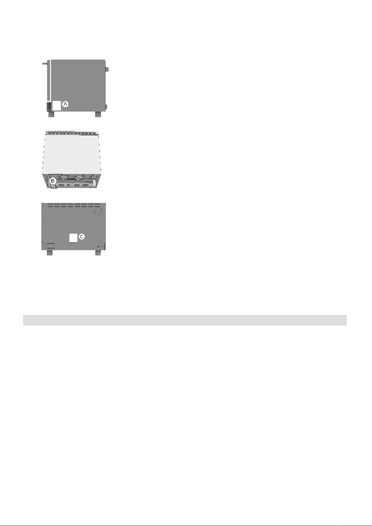
1.3 TRANSPORT DES OFENS UND ENTFERNUNG DER VERPACKUNG
Beim Eingang des Ofens und vor der Installation, überprüfen, daß die Verpackung intakt ist und es keine sicht-
liche Schäden gibt.
Überprüfen Sie, daß es zusammen mit dem Ofen die dazugehörigen Dokumentation gibt und zwar:
• Installation.Gebrauch-und Wartungsanleitungen
• Formular für die Überprüfung der korrekten Installation
• Schaltplan
• Etikette ISO 3864-1
Vor dem Transport des Ofens bis zu dem Punkt, wo er installiert werden muss, überprüfen Sie daß:
• Die Türen sind groß genug um den Durchgang des Ofens zu gewähren;
• Der Bodenbelag das Gewicht tragen kann.
Je nach dem Modell des Ofens, seinen Abmessungen und seinem Gewicht, geeignete Einrichtungen verwenden,
um die Ware während Transport und Installation zu bewegen, um die Stabilität zu gewähren und Fälle, Umkippen
oder unkontrollierte Bewegung des Gerätes und seine Teile zu vermeiden.
Die Verpackung des Ofens halten, bis der Ofen installiert wird.
Die Verpackung macht die Bewegung der Ware einfacher und schützt den Ofen vor zufälligen Stößen.
Während des Umzugs und der Installation des Ofens, muss der Installateur die Unfallverhütungsvorschriften in
Kraft am Ort der Installation respektieren (Verwendung von Sicherheitsschuhe, Handschuhe usw.).
Die Verpackung entfernen, ohne den Ofen zu schaden. Die Klebefolie, die die Edelstahloberäche schützt kann
entfernt werden, auch nach der Platzierung des Ofens über das entsprechende Untergestell oder auf der Auage-
äche.
ACHTUNG: Die Materialen der Verpackung und die Klebefolie sind potenziell gefährlich.
Aus diesem Grund sollen sie außerhalb der Reichweite der Kinder und richtig gehalten werden,
in Übereinstimmung der lokalen Bestimmungen.
Sie sollten die Verpackungsmaterialen (Holz, Pappe, Plastik...) trennen und entsorgen Sie diese
separat, in Übereinstimmung der gültigen Vorschriften am Ort der Installation.
Achtung: Vor Inbetriebnahme des Geräts die Schutzfolie von den Stahlteilen abziehen. Dafür dürfen keine Scheu-
ermittel bzw. Metallgegenstände verwendet werden.
Klebrige Rückstände mit einem in Lösungsmittel getränkten Schwamm entfernen.
Wenn der Ofen in Betrieb gesetzt wird, ohne die Klebfolie wegzunehmen, wird die Entfernung der Klebfolie und
die Reinigung der klebrigen Rückstände immer schwieriger.
DE

18
1.4 INFORMATIONSETIKETTEN
Auf jedem Ofen nden Sie Metalletiketten, die wichtige Info über Merkmale des Ofens, Strom-und Wasseran-
schlüsse und eventuell Ablaufanschluss geben.
Auf der rechten Wand liegt die Etikette A.
Die Informationen auf dieser Etikette sind die folgende:
• Name und Adresse des Herstellers
• Ofenmodell
• IPX-Schutz gegen Wasserstrahl
• Konformität europäischen Vorschriften
• Leistung und Art der Stromversorgung (einphasig oder dreiphasig).
• Seriennummer der Öfen
• Symbol der europäischen Vorschrift 2012/19/UE
Durch das Entfernen der hinteren Wand, nden Sie auf Ofenboden die Etiket-
te B.
Auf dieser Etikette wird die Seriennummer des Ofens wiederholt.
Auf diesem Fall, kann der Kunde oder der Installateur die Seriennummer des
Ofens nden, wenn die Etikette A schmutzig oder geschädigt ist.
Wenn der Ofen mit Beschwadung ausgerüstet ist, am Rücken des Ofens,
neben dem Verbinder für Wasseranschluss liegt die Etikette C.
Die Etikette C zeigt die notwendigen Wassermerkmale für einen korrekten
Betrieb des Ofens.
Die gleichen Merkmale sind am Abschnitt 2.4 dieses Handbuchs gelistet.
INSTALLATION
1.5 POSITIONIERUNG DES OFENS
Die Wasser- und Stromversorgungsanlagen, sowie der Aufstellort, müssen den geltenden Installations- und Si-
cherheitsbestimmungen entsprechen.
Das Lokal, wo der Ofen installiert werden soll, muss die folgenden Anforderungen erfüllen und zwar:
• Vor Witterungseinüssen geschützt werden und einen ausreichenden Luftaustausch haben;
• Einhaltung der Vorschriften zur Arbeitssicherheit;
• Eine Raumtemperatur zwischen 5°C und 35°C mit Feuchtigkeit nicht über 70%;
Stellen Sie den Ofen in Gleichgewicht durch den verstellbaren Füßen.
Für die Tischaufsatzgeräte halten Sie einen Abstand von min. 6 cm vom Ofenboden und dem Tisch (Fußstütze).
Einen Hinterabstand halten, damit die Etikette für EquipotentialKlemme sichtbar ist, wenn der Ofen installiert
wird.
Die gleiche Klemme muss zugänglich sein, um Pa Kabel zu installieren, nachdem der Ofen gemäß der Be-
dienungsanleitungen installiert worden ist. Das Gerät so aufstellen, dass die rechte Seite des Geräts für In-
stallations-, Wartungs- und Reparaturarbeiten zugänglich sind. Den Mindestabstand zwischen den Wänden des
Backofens (hintere Wand und rechte Seitenwand) und Mauern oder anderen Geräten beachten.
1.7 ELEKTROANSCHLUSS
Das Gerät wird werksgemäß für den Betrieb mit der auf dem Typenschild (auf der rechten Seite des Geräts
angebracht) angegebenen Versorgungsspannung eingestellt. Des weiteren muss das Gerät in ein Potentialaus-
gleichssystem eingeschlossen werden, dessen Wirksamkeit den geltenden Richtlinien entsprechen muss.
Der Anschluss wird mit der Schraube am Rücken des Ofens durchgeführt, die mit EQUIPOTENTIAL gekennzeichnet
ist und sich in der Nähe der Kabelklemme bendet.
Die Herstellerrma übernimmt bei Nichtbeachtung dieser Unfallverhütungsmaßnahme keine Veran-
twortung.
Wenn das Netzkabel beschädigt ist, muss es durch den Kundendienst oder eine ähnlich qualizierte Person ersetzt
werden, um jegliches Risiko zu vermeiden.
DE

19
1.7 TABELLE TECHNISCHE DATEN ELEKTROANSCHLUSS
Modelle Leistung und
Spannung Anz. und
Motorleistung Heizleistung Grillleistung Strom
4 x 2/3 GN
4 x 460x340
Heissluft
2.7 kW
220-240 V 1N ~
50/60 Hz 1 x 55 W 2.65 kW -- 11.7 A
4 x 2/3 GN
4 x 460x340
Beschwadung
2.7 kW
220-240 V 1N ~
50/60 Hz 1 x 55 W 2.65 kW -- 11.7 A
4 x 2/3 GN
4 x 460x340
Heissluft
verstärkt
3.2 kW
220-240 V 1N ~
50/60 Hz 2 x 55 W 3.1 kW -- 13.5 A
4 x 2/3 GN
4 x 460x340
Beschwadung
verstärkt
3.2 kW
220-240 V 1N ~
50/60 Hz 2 x 55 W 3.1 kW -- 13.5 A
4 x 2/3 GN
4 x 460x340
Heissluft
verstärkt grill
3.6 kW
220-240 V 1N ~
50/60 Hz 2 x 55 W 2.8 kW 0.7 kW 15.6 A
4 x 2/3 GN
4 x 460x340
Beschwadung
verstärkt grill
3.6 kW
220-240 V 1N ~
50/60 Hz 2 x 55 W 2.8 kW 0.7 kW 15.6 A
4 x 2/3 GN
4 x 460x340
mit Dampf
3.3 kW
220-240 V 1N ~
50/60 Hz 1 x 240 W 3.0 kW -- 14.6 A
4 x 60x40
Heissluft
5.8 kW
380–415 V 3N ~
50/60 Hz
1 x 240 W 5.5 kW -- 15.4 A
4 x 60x40
4 x 1/1 GN
Beschwadung
3.2 kW
220-240 V 1N ~
50/60 Hz 2 x 55 W 3.1 kW -- 13.5 A
4 x 60x40
4 x 1/1 GN
Beschwadung
verstärkt
4.9 kW
380–415 V 3N ~
50/60 Hz
2 x 55 W 4.8 kW -- 13.5 A
4 x 60x40
4 x 1/1 GN
Beschwadung
grill
3.6 kW
220-240 V 1N ~
50/60 Hz 2 x 55 W 2.8 kW 0.7 kW 15.6 A
4 x 60x40
4 x 1/1 GN
mit Dampf
5.8 kW
380–415 V 3N ~
50/60 Hz
1 x 240 W 5.5 kW -- 15.4 A
Die einphasigen Öfen sind mit einem Stromkabel ausgestattet, während die dreiphasigen Öfen ein 5x1,5 mm2
Kabel benötigen.
DE

20
2.5 ANSCHLUSS ANS WASSERNETZ – WASSERZUFUHR
Wenn das manuelle Befeuchtungssystem installiert ist (optional), sind die Geräte auf der Rückseite mit einem
Wasseranschluss ausgerüstet. Zwischen dem Gerät und dem Wasserversorgungsnetz muss ein leicht
zugängliches Absperrventil zwischengeschaltet werden.
Außerdem ist es ratsam, in der Wasserzuleitung einen Filter mit Einsatz zu montieren.
Der Wasseranschluss muss immer mit Kaltwasser erfolgen.
Die Wasserversorgung muss für den Menschengebrauch geeignet ist und das die folgenden Merkma-
le hat:
Temperatur: muß zwischen 15 und 20°C liegen
Wasserhärte: Diesem Gerät muß Wasser zugeführt werden, dass eine Härte von 4 bis 12 französischen Gra-
den aufweist. Es wird empfohlen einen Entkalkter dem Gerät beizugeben, damit der Härtegrad des Wassers
zwischen diesen Werten liegt. Wird Wasser mit höherem Härtegrad verwendet, entstehen innerhalb kurzer Zeit
Kalkablagerungen auf den Garraumwänden.
Wasserdruck: zwischen 150 und 250 KPa (1,5 – 2,5 bar).
ACHTUNG. Höhere Drücke führen zu übermäßigen Wasserverbrauch und können wichtige Komponente beschä-
digen.
Maximale Chlorid konzentration (Cl-): unter 150 mg/Liter.
Chlorkonzentration (Cl2): unter 0.2 mg/Liter.
pH: über 7
Leitfähigkeit des Wassers: von 50 bis 2000 µS/cm.
Achtung: Die Verwendung anderer Wasseraufbereitungssysteme als das von der Herstellerrma gelieferte ist
unzulässig und führt zum vollständigen Verfall der Garantie. Der Einsatz von Geräten zur Dosierung von Mitteln
zur Vermeidung von Ablagerungen in den Rohrleitungen (z.B. Polyphosphat Dosierter) ist ebenfalls untersagt,
da diese die einwandfreie Funktion der Maschine beeinträchtigen können.
3.1 AUSTAUSCH DER ERSATZTEILE
Die Ersetzung von beschädigten Teilen muss unbedingt mit Fachpersonal folgen. Um dem Hersteller nach Ersatz-
teilen zu fragen, muss man immer das genaue Ofensmodell und die Seriennummer mitteilen.
Diese Daten nden Sie auf der Etikette Technische Daten auf der rechten Seite des Ofens (Absatz 1.4).
Bevor die Ersatzteile ausgetauscht werden, muss aus Sicherheitsgründen der elektrische Schutzschalter ausge-
schaltet und das Wassersperrventil, geschlossen werden.
3.2 KONTROLLE DER FUNKTIONEN
Wenn die Installation fertig ist, muss man überprüfen daß alle Röhre wassergeprüft und eventuell gasgeprüft sind.
Der Installateur muss den regelmäßigen Betrieb des Ofens kontrollieren, dem Kunden die notwen-
digen Hinweisungen erteilen und ihm auch die Bedienungsanleitungen geben, die er gewissenhaft
folgen muss.
Die seitige Etikette ISO 3864-1 muss auf eine sichtbare Oberäche aufgeklebt werden, auf
eine Höhe von 1.6 Mt vom Boden.
Auf Tischmodelle ist die Etikette schon in der geeigneten Position aufgeklebt.
Auf Standgeräte wird die Etikette zusammen mit Ofenunterlagen geliefert; sie muss nach
der Installation auf eine sichtbare Oberäche auf eine Höhe von 1.6 Mt vom Boden aufge-
klebt werden. Der Installateur muss den regelmäßigen Betrieb des Ofens kontrollieren, dem
Kunden die notwendigen Hinweisungen erteilen und ihm auch die Bedienungsanleitungen
geben, die er gewissenhaft folgen muss.
WICHTIG: Bevor der Benutzer den Ofen einschaltet und einen Gar-oder Waschzyklus einstellt, ist es notwendig
der Installateur oder ein Fachtechniker überprüft dass alle Verbindungen in Ordnung sind gemäß der Bedien-
anleitungen.
Der Techniker oder der Installateur müssen das folgende überprüfen:
• Der Ofen muss stehen (waagrecht) und an einem Untergestellt oder Regal setzen, um stabil zu sein.
• Elektroanschlüsse müssen gemäß der Richtlinien sein und der Querschnitt der Anschlusskabeln soll nicht kleiner
als den in den Bedienungsanleitungen sein.
• Druck und Härte des Wassers, das den Ofen versorgt müssen die Werte der Bedienungsanleitung entsprechen;
• Im Fall der Ofen mit Ablauf ausgestattet ist, soll er korrekt installiert werden und die Materialen die Betriebs-
temperaturen widerstehen.
Nachdem Sie alles überprüft haben, den Wasserabsperrventil und der Schutzschalter, alle rückwärts montiert.
Der Installateur muss den regelmässigen Betrieb des Ofens überprüfen und dem Benutzer den notwendigen Be-
dienanleitungen geben.
Der Installateur soll das Formular für die korrekte Installation ausfüllen und unterschreiben und der
Kunde soll es für die Garantiezeit des Ofens auf bewahren.
DE
This manual suits for next models
58
Table of contents
Languages:
Other Inoxtrend Convection Oven manuals

Inoxtrend
Inoxtrend CDA-107G Manual

Inoxtrend
Inoxtrend RUA-110 Series Manual

Inoxtrend
Inoxtrend Compact Series Specification sheet

Inoxtrend
Inoxtrend GCA-GUA 304 User manual

Inoxtrend
Inoxtrend RDT-104E Parts list manual

Inoxtrend
Inoxtrend GUA-304EB User manual

Inoxtrend
Inoxtrend GUP-304ES User manual

Inoxtrend
Inoxtrend GUP 304 User manual

Inoxtrend
Inoxtrend GUA 304 EB User manual

Inoxtrend
Inoxtrend ER304-CAE User manual