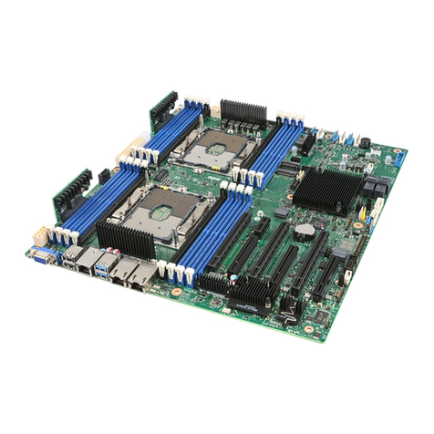
manuals.online logo
Brands
  1. Home
  2. •
  3. Brands
  4. •
  5. Intel
  6. •
  7. Server Board
  8. •
  9. Intel SDS2 User manual

Intel SDS2 User manual

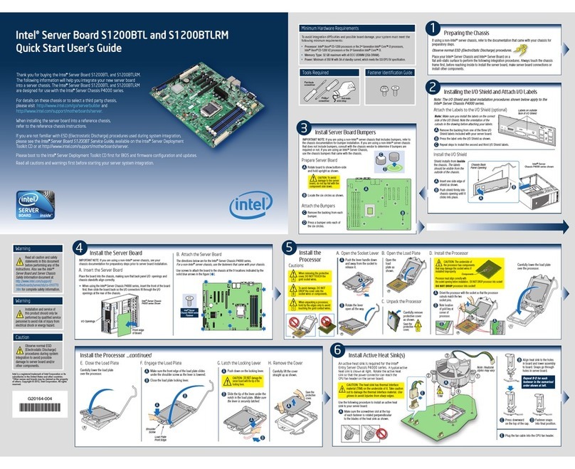
2Installing the Processor[s]
A58837-004
Open the Socket Lever
A
Attaching the Processor to the Socket
B
Installing the Heat Sink and Retention Clip
C
Locking the Heat Sink Retention Clip
D
Intel Server
Board SDS2
Quick Start
User Guide
2
3
1
Go to SIDE 2 to finish configuration
Notes and CAUTIONS:
1. If only ONE processor is to be used, it must be
installed in Primary Processor Socket [#1] and
a TERMINATOR must be installed in the
Secondary Processor Socket [#2]. See Step F
“Installing a Processor Terminator”.
2. When unpacking a processor, hold by the
edges only to avoid touching the pins.
4. This server board has “zero-insertion force”
sockets. If processor does not drop easily into
socket holes, make sure lever is in the full-up
position.
Close and latch
socket lever.
Align corner
mark on the
processor to the
socket as shown.
Align features 1, 2, and 3 during
assembly as shown.
Use slow, constant pressure
to close retention lever.
Installing a Terminator
F
If only ONE processor is to be installed, a terminator
must be installed in the Processor Socket 2
as shown below.
Close and latch
socket lever
Align corner marks on
terminator with the
“handle-side”of the
processor socket.
Attaching the Fan
E
Install the heat sink fan by snapping it onto the
top of the heat sink as shown.
See Step #6 for processor fan
cabling to server board
A
A
DID YOU KNOW?
You can use the bag from your server board
as an anti-static pad while installing and
configuring components.
Intel and Pentium are registered trademarks of Intel Corporation or its subsidiaries in the United States and other countries. *Other names and brands may be claimed as the property of others. Copyright © 2001, Intel Corporation. All rights reserved.
1Installing the I/O Shield and Gasket
Attaching the Gasket to the I/O Shield
AInstalling the I/O Shield
C
2
Press the gasket
onto the inside face
of the I/O shield
as shown.
1
Remove two backing
strips from gasket.
Shield installs
from inside
of chassis.
2
1
Rotate into chassis opening
until shield snaps into place.
Insert top edge
as shown.
Start Here
Thank you for buying an Intel Server Board. The
following information will help you prepare your server
board for integration with your selected server chassis.
This Guide is for technically qualified persons.
Expanded installation instructions and complete product
information are available in the Intel Server Board
SDS2 Product Guide located on the Resource CD.
See the Intel Server Board SDS2 Product Guide for
product Safety and EMC regulatory compliance information.
Before you begin
You will need the following tools and equipment:
Minimum Hardware Requirements
To avoid integration difficulties and possible board
damage, your system must meet the following
minimum requirements:
• Processor: Minimum of one Intel Pentium III
processor with 256K cache support.
• Memory: Minimum of two identical PC133 compliant,
3.3 V, ECC, registered SDRAM 168 pin
DIMMs, of minimum size 64MB.
• Power Supply: Minimum of 275 W with 1.2 A +5 V
standby current and +12 V CPU power support [ATX].
If you are not familiar with ESD [Electro-Static Discharge]
Procedures to be used during system assembly, complete
ESD Procedures are described in your Intel Server Board
SDS2 Product Guide.
Needle-nosed
pliars
Anti-static
wrist strap
Phillips*
screw driver
Flat blade
screw driver
Build Value With Intel
4Installing Chassis Standoffs
For installation in the SC5100 chassis, install additional
standoffs in positions 7 and 17. Standoff numbering in
other chassis may be different. Standoffs are included
with your chassis.
1 S
6
S
19 26
4
5
18 23
17
7
3Installing Memory
Step #1: Open both DIMM
Socket Levers.
Step #3: Check that
socket levers are
securely latched.
Step #2: Insert DIMM making
sure the connector edge of the
DIMM aligns correctly with the slot.
DIMM Memory Modules
Avoid touching
gold contacts
when handling or
installing DIMMs.
Note: See “Minimum Hardware Requirements” in
the Start Here box above left for correct DIMM
specifications.
Memory banks must be populated in pairs.
Support for 2-way memory interleaving requires
the use of identical memory modules.
1
2
3
1A
1B
®
For more information on Intel's added-value
server offerings, visit the Intel ServerBuilder
website at:
Available only to Intel Channel Program
Members, part of Intel e-Business Network.
www.intel.com/go/serverbuilder
High-quality server building blocks
Extensive breadth of server building blocks
Solutions and tools to enable e-Business
Comprehensive training services
Worldwide 24x7 technical support [AT&T
Country Code + 866-655-6565]
World-class service, including a three-year
warranty and Advanced Warranty
Replacement
Get the high-value server solutions you need by
taking advantage of the outstanding value Intel
provides to system integrators:
Processor
Socket 2
Terminator
goes here
if only one
processor
is used
F
2
1A 1B 3B
3A
2A 2B
DIMM
Sockets
3
IDE
Connector
SCSI A SCSI B 7
Processor
Socket 1 A
2
COM2
Connector
8
Information in this document is provided in connection with Intel products. No license, express or implied, by estoppel or otherwise, to any intellectual property rights is granted by this document. Except as provided in Intel's Terms and Conditions of Sale for such products, Intel assumes no liability whatsoever, and Intel disclaims any express or implied warranty, relating to sale and/or use of
Intel products including liability or warranties relating to fitness for a particular purpose, merchantability, or infringement of any patent, copyright or other intellectual property right. Intel products are not intended for use in medical, life saving, or life sustaining applications. Intel may make changes to specifications and product descriptions at any time, without notice.
® Server Products, Programs and Support
Product information including product
briefs and technical product specifications
Sales tools such as videos and
presentations
Configurator Tools to help you build
complete solutions
Training information such as the Intel
Online Learning Center
Support Information and much more
Intel ServerBuilder is your one-stop shop for
information about all of Intel's Server Building
Blocks such as:
Additional resources and support for your server
board, including specifications and software updates, can
be found at:
http://support.intel.com/support/motherboards/server/SDS2
For a list of qualified memory and chassis components, see:
http://support.intel.com/support/motherboards/server/SDS2
3. Do not mix processors of different types or
frequencies.
Attaching the Label to the I/O Shield
B
1.Remove the backing from the label included with
 your server board.
2.Press the label onto the outside face of the I/O shield.
Outside face
of I/O shield
PARALLEL
KYBD
MOUSE
10/100MB
NET
1
2
3
USB
®
®
®
®
®
http://support.intel.com/support/motherboards/server/SDS2
®
®
®
Translations of the Intel Server Board Product Guide
are available at:
La traducción de la Guía del Producto Intel Server Board
se encuentra disponible en:
•
•
•
•
•
•
•
•
•
•
•
Side 2
Cable Routing
7
IDE and SCSI Cables
A
Floppy Drive and Front Panel USB Cables
B
Side 2
6Making Connections to the Server Board
A
E
A
T
A
1
0
0
D
C
S
C
S
I
N
I
H
G
Server Board Connection Quick Reference:
A. Main Power
B. +12V CPU Power
C. Front Panel USB
D. Floppy Disk Drive
E. ATA100/IDE
F. Front Panel
G. SCSI B
H. SCSI A
I.
J.
K.
L. COM2/EMP
M. Chassis Intrusion
N.
K
L
8Installing the COM2 Cable
Finishing Up
9
Video
Parallel
Port
Network
Keyboard
Mouse
USB 1, 2 & 3
COM2
Serial Port
AC
Power
Ribbon Cable[s]
Lower Device Bay
Cabling to Lower Device Bay
1. Remove the top half of the epac.
2. Route cable[s] as shown.
3. Replace the top half of the epac.
IDE and SCSI cables that connect to devices
in the lower device bays should be routed
around the epac as shown.
SCSI Backplane
USB Cable
Floppy Disk
Cable
Route the floppy drive cable and the
front panel USB cable as shown.
2
1
5Installing the Server Board
2
1. Place the board into the chassis, making sure
 that the back panel I/O shield openings and
 chassis standoffs align correctly.
2. Attach the board with the screws included with
 your chassis.
For installation in the Intel SC5100 chassis:
1
1. Replace the chassis cover.
2. See your chassis documentation to complete rack or pedestal
installation.
3. Connect your keyboard, mouse, video and other I/O cables as shown.
Then connect the AC Power cable.
Before installing your operating system, you must finish your chassis
installation and connect I/O connectors and AC power.
1. Install the COM2 cable by inserting into the chassis back panel cutout and attaching
with two hex screws as shown. Note that it installs from the inside and the screws
fasten from the outside. Use a small flat-blade screwdriver.
For the Intel SC5100 chassis, you can connect the COM2 serial port cable to either
the front or back panels. Connecting it to the back panel is illustrated below.
2. Attach the other end to the COM2 connector located
on your server board between the CPU2 Processor
socket and the DIMMs. See step 6 for
exact COM2 connector location on
the server board.
Chassis Back
Panel
Insert
from inside
chassis
Screwdriver
Slot
B
2
1
COM1
Serial Port
Getting Started with Intel Server Management [Optional]
10
Reference
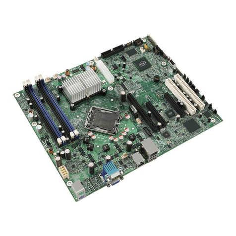
Component Descriptions:
C
D
B
F G JH LK
U
M
O
N
Q
P
R
S
T
Z Y
A
W
VX
EI
A. Chassis Intrusion
B.  CPU Fan 2
C. Back Panel I/O Ports
D.  Fan 4
E. Fan 3
F.  Main Power
G. CPU Fan 1
H. CPU 1
I.  CPU 2
J.  COM2/EMP
K. +12 V CPU Power
L.  DIMMs
M. USB
N. Floppy
O.  IDE
P.  Fan 2
Q.  Fan 1
R.  Jumper Block CN42
S.  Jumper Block CN46-CN49
T.  Battery
U.  Speaker
V.  SCSI B
W. Front Panel
X. SCSI A
Y. 64/66 MHz PCI
Z. 32/33 MHz PCI
Server Board Component Layout
The system does not boot or show video at power on.
• If configuring with only one processor verify that the processor is in the Primary
 Processor socket (CPU 1) and that the processor terminator module is installed in the
 Secondary Processor socket (CPU 2).
• Beep code 1-3-3-1 means you have unrecognized or bad memory. Remove and
 replace DIMMs one at a time to isolate which one is causing problems.
• Remember, all DIMMs must be:
 • Registered PC133 compliant
 • The same speed
 • From the same manufacturer
 • Installed beginning with DIMM 1
 • Installed with no empty sockets in between
• Your power supply must provide 1.2 A of +5 V Standby current to support WOL.
 If the standby current is not present, your board will not boot.
The system sometimes works, but is exhibiting erratic behavior.
• This is typically the result of using an under-rated power supply.
 Make sure you are using at least a 275 W power supply.
Common Problems and Solutions Accessories and Order Codes
SDS2
KHD2BASE300Intel SC5100 Server Chassis Base Chassis
Intel Server Board SDS2
KHD2HSRP350R
Intel SC5100 Server Chassis Rack Optimized
Redundant Power Chassis
Product Code
Item
KHD2HSRP350
Intel SC5100 Server Chassis Redundant Power
Chassis
FHD2SPRS
Intel SC5100 Server Chassis spares kit
SRCMR
Intel RAID Controller SRCMR
Installing the Service Partition
Installing the Service Partition consists of three tasks:
• Preparing the server to boot from the CD-ROM drive
• Creating the Service Partition
• Formatting the Service Partition
Preparing the Server to Boot from the CD-ROM Drive
1. Insert the Intel Server Board SDS2 Resource CD into the server's
CD-ROM drive.
2. Restart the server.
3. Press <F2> at the prompt to enter the BIOS setup utility
during the boot cycle.
4. Select Boot Menu.
5. In Boot Device Priority, press the <+> key to move ATAPI* CD-ROM
device higher in priority than the system hard drive.
6. Press the <F10> key to save the settings. After pressing this key, the
system resets and boots from the CD-ROM drive.
Creating the Service Partition
1. From the CD-ROM menu, select Utilities and press the <Enter> key.
2. Select Run Service Partition Administrator and press the <Enter> key.
3. From the list of available items, select Create Service Partition-first time.
4. Follow the instructions that appear on the screen. These instructions
 prompt you to reboot the server. It will reboot from the CD-ROM.
Install your operating system now.
1. Insert the Intel Server Board SDS2 Resource CD into the system's CD
ROM drive and wait for the auto-launcher to display a start-up web
page local to the Intel Server Board SDS2 Resource CD.
2. From the start-up web page, open server management in the blue menu
on the left side of the screen.
3. Open make a selection in the green box.
4. Choose to either view the Intel Server Control Installation Guide or to
proceed with the software installation.
5. To continue with the installation, click on Intel Server Control and then
on run installer. After clicking on run installer, follow the screen instructions.
Installing your Operating System
Installing Intel Server Control
Formatting the Service Partition
1. After the system reboot, select the Utilities menu and press the <Enter> key.
2. Select Run Service Partition Administrator and press the <Enter> key.
3. Select Format Service Partition and Install Software.
4. Remove the System Resource CD from the CD-ROM drive and exit from the
menu screen. You can now install the server's operating system.
Intel Server Control and the hard drive Service Partition provide real-time
monitoring and alerting for your SDS2 server hardware, emergency
remote management, and remote server setup. Intel Server Control is
implemented by installing it within client-server architecture.
The Service Partition provides you with the ability to remotely access a
local partition on the server and to identify and diagnose server health
issues. Remote access is provided through either a modem or network
connection.
To get started with Intel Server Management, you install the Service
Partition first, then the system's operating system, and finally Intel Server
Control. The information here describes installation on a system running a
Microsoft Windows* operating system.
M
®
®
®
®
®
®
®
®
®
®
F
J
Chassis fans
CPU1 Fan
Epack Fans[2]
CPU2 Fan

Other manuals for SDS2

2

Other Intel Server Board manuals

Intel S1200V3RP Configuration guide

Intel

Intel S1200V3RP Configuration guide

Intel S5500BCR User manual

Intel

Intel S5500BCR User manual

Intel L440GX+ User manual

Intel

Intel L440GX+ User manual

Intel S2600KPR Series User manual

Intel

Intel S2600KPR Series User manual

Intel SE7520BD2 User manual

Intel

Intel SE7520BD2 User manual

Intel SE7525RP2 User manual

Intel

Intel SE7525RP2 User manual

Intel S1200RP User manual

Intel

Intel S1200RP User manual

Intel SR1400SYS - Server Platform - 0 MB RAM User manual

Intel

Intel SR1400SYS - Server Platform - 0 MB RAM User manual

Intel SE7221BA1 User manual

Intel

Intel SE7221BA1 User manual

Intel SE7501CW2 Quick setup guide

Intel

Intel SE7501CW2 Quick setup guide

Intel S845WD1-E - Server Board Motherboard User manual

Intel

Intel S845WD1-E - Server Board Motherboard User manual

Intel SE7500CW2 User manual

Intel

Intel SE7500CW2 User manual

Intel S5500HCV Guide

Intel

Intel S5500HCV Guide

Intel SE7221BK1-E - Server Board - Mainboard Configuration guide

Intel

Intel SE7221BK1-E - Server Board - Mainboard Configuration guide

Intel SE7520AF2 User manual

Intel

Intel SE7520AF2 User manual

Intel S3420GPRX User manual

Intel

Intel S3420GPRX User manual

Intel S3420GPLC - Server Board Motherboard User manual

Intel

Intel S3420GPLC - Server Board Motherboard User manual

Intel SE7230NH1-E User manual

Intel

Intel SE7230NH1-E User manual

Intel S1200SPL User manual

Intel

Intel S1200SPL User manual

Intel SE7230NH1-E User manual

Intel

Intel SE7230NH1-E User manual

Intel SE7500CW2 Configuration guide

Intel

Intel SE7500CW2 Configuration guide

Intel S2600CO Family Configuration guide

Intel

Intel S2600CO Family Configuration guide

Intel S2400SC Configuration guide

Intel

Intel S2400SC Configuration guide

Intel S845WD11U User manual

Intel

Intel S845WD11U User manual

Popular Server Board manuals by other brands

Advantech ASMB-805 Series Startup manual

Advantech

Advantech ASMB-805 Series Startup manual

Abit SI-1Ns40 user manual

Abit

Abit SI-1Ns40 user manual

MSI K9ND Master-A4R user guide

MSI

MSI K9ND Master-A4R user guide

IWILL DK8-HTX Hardware installation guide

IWILL

IWILL DK8-HTX Hardware installation guide

MSI MS-S0221 manual

MSI

MSI MS-S0221 manual

TYAN Transport GS14 (B5121G14S2) manual

TYAN

TYAN Transport GS14 (B5121G14S2) manual

MSI MS-S0031 user manual

MSI

MSI MS-S0031 user manual

MSI E7210 MasterX-FA2R user guide

MSI

MSI E7210 MasterX-FA2R user guide

Supero H8DA3-2 user manual

Supero

Supero H8DA3-2 user manual

Meinberg TCR167PCI operating instructions

Meinberg

Meinberg TCR167PCI operating instructions

MSI E7230 Master-FA4R user guide

MSI

MSI E7230 Master-FA4R user guide

manuals.online logo
manuals.online logoBrands
  • About & Mission
  • Contact us
  • Privacy Policy
  • Terms and Conditions

Copyright 2025 Manuals.Online. All Rights Reserved.