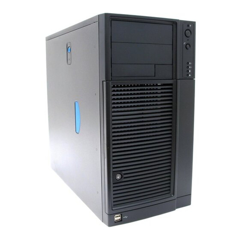
Intel® Server Board S2600TP and Intel® Compute Module HNS2600TP Product Family
viii
List of Figures
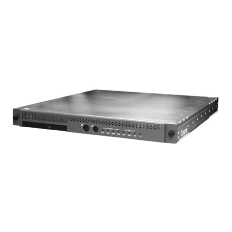
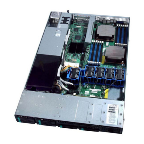
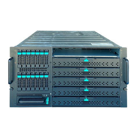
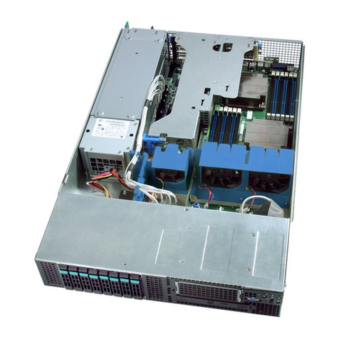
Figure 1. Intel® Compute Module HNS2600TP................................................................................................................1
Figure 2. Server Board Rear Connectors............................................................................................................................4
Figure 3. HNS2600TPR/HNS2600TPFR Compute Module Back Panel Features..............................................4
Figure 4. HNS2600TP24R/HNS2600TP24SR Compute Module Back Panel Features...................................4
Figure 5. Power Docking Board Features...........................................................................................................................4
Figure 6. SAS/PCIe* SFF Combo Power Docking Board Feature..............................................................................5
Figure 7. Bridge Board Features.............................................................................................................................................5
Figure 8. SAS/PCIe* SFF Combo Bridge Board Features .............................................................................................5
Figure 9. Server Board Features.............................................................................................................................................6
Figure 10. Intel® Light-Guided Diagnostic LEDs –Server Board .................................................................................6
Figure 11. Configuration and Recovery Jumpers..............................................................................................................7
Figure 12. Cable Routing...........................................................................................................................................................10
Figure 13. Removing the Air Duct .........................................................................................................................................10
Figure 14. Installing the Air Duct...........................................................................................................................................11
Figure 15. Removing the Processor Heatsink ..................................................................................................................12
Figure 16. Installing the Processor –Open the Socket Lever....................................................................................12
Figure 17. Installing the Processor –Open the Load Plate........................................................................................13
Figure 18. Installing the Processor –Install the Processor ........................................................................................14
Figure 19. Installing the Processor –Remove the Cover.............................................................................................14
Figure 20. Installing the Processor –Close the Load Plate ........................................................................................14
Figure 21. Installing the Processor –Latch the Locking Lever..................................................................................14
Figure 22. Installing the Processor Heatsink....................................................................................................................15
Figure 23. Installing the Memory ..........................................................................................................................................16
Figure 24. Removing the PCIe* Riser Assembly –Step 1 ............................................................................................16
Figure 25. Removing the PCIe* Riser Assembly –Step 2 ............................................................................................17
Figure 26. Removing the Filler Panel from the PCIe* Riser Assembly...................................................................17
Figure 27. Installing the PCIe* Add-in Card......................................................................................................................17
Figure 28. Installing the PCIe* Riser Assembly –Step 1..............................................................................................18
Figure 29. Installing the PCIe* Riser Assembly –Step 2..............................................................................................18
Figure 30. Removing the PCIe* Riser Assembly –Step 1 ............................................................................................18
Figure 31. Removing the PCIe* Riser Assembly –Step 2 ............................................................................................19
Figure 32. Removing the PCIe* Add-in Card.....................................................................................................................19
Figure 33. Inserting the Filler Panel to the PCIe* Riser Assembly...........................................................................19
Figure 34. Installing the PCIe* Riser Assembly –Step 1..............................................................................................20
Figure 35. Installing the PCIe* Riser Assembly –Step 2..............................................................................................20
Figure 36. Removing the PCIe* Riser Assembly –Step 1 ............................................................................................20
Figure 37. Removing the PCIe* Riser Assembly –Step 2 ............................................................................................21
Figure 38. Removing the PCIe* Add-in Card.....................................................................................................................21
Figure 39. Removing the PCIe* Riser from the Riser Assembly Bracket...............................................................21
Figure 40. Installing the PCIe* Riser to the Riser Assembly Bracket ......................................................................22
Figure 41. Installing the PCIe* Add-in Card......................................................................................................................22
Figure 42. Installing the PCIe* Riser Assembly –Step 1..............................................................................................22
Figure 43. Installing the PCIe* Riser Assembly –Step 2..............................................................................................22
Figure 44. Removing the Bracket from the IOM Riser and Carrier Assembly.....................................................23
Figure 45. Installing the IO Module to the IOM Riser and Carrier Assembly ......................................................23
Figure 46. Installing the Bracket to the IOM Riser and Carrier Assembly ............................................................23
Figure 47. Removing the Filler Panel...................................................................................................................................24
Figure 48. Installing the IOM Riser and Carrier Assembly ..........................................................................................24
