manuals.online logo
Brands
  1. Home
  2. •
  3. Brands
  4. •
  5. NIVELCO
  6. •
  7. Switch
  8. •
  9. NIVELCO NIVOSWITCH R-400 Series User manual

NIVELCO NIVOSWITCH R-400 Series User manual

This manual suits for next models

1

Other NIVELCO Switch manuals

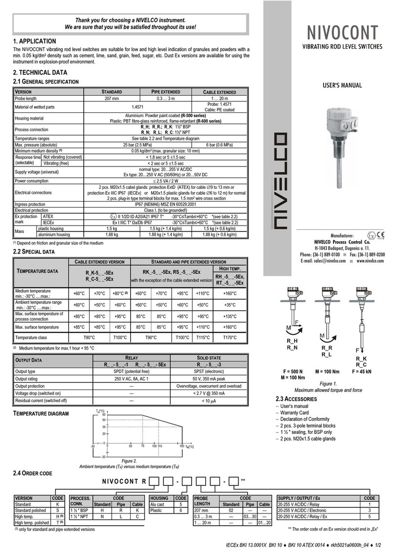
NIVELCO NIVOCONT R Series User manual

NIVELCO

NIVELCO NIVOCONT R Series User manual

NIVELCO NIVOFLOAT NW-100 Series User manual

NIVELCO

NIVELCO NIVOFLOAT NW-100 Series User manual

NIVELCO NIVOCONT K User manual

NIVELCO

NIVELCO NIVOCONT K User manual

NIVELCO R-400 User manual

NIVELCO

NIVELCO R-400 User manual

NIVELCO Nivocap CK User manual

NIVELCO

NIVELCO Nivocap CK User manual

NIVELCO NIPRESS DK-300 Assembly instructions

NIVELCO

NIVELCO NIPRESS DK-300 Assembly instructions

NIVELCO NIVOFLIP MAK-200 User manual

NIVELCO

NIVELCO NIVOFLIP MAK-200 User manual

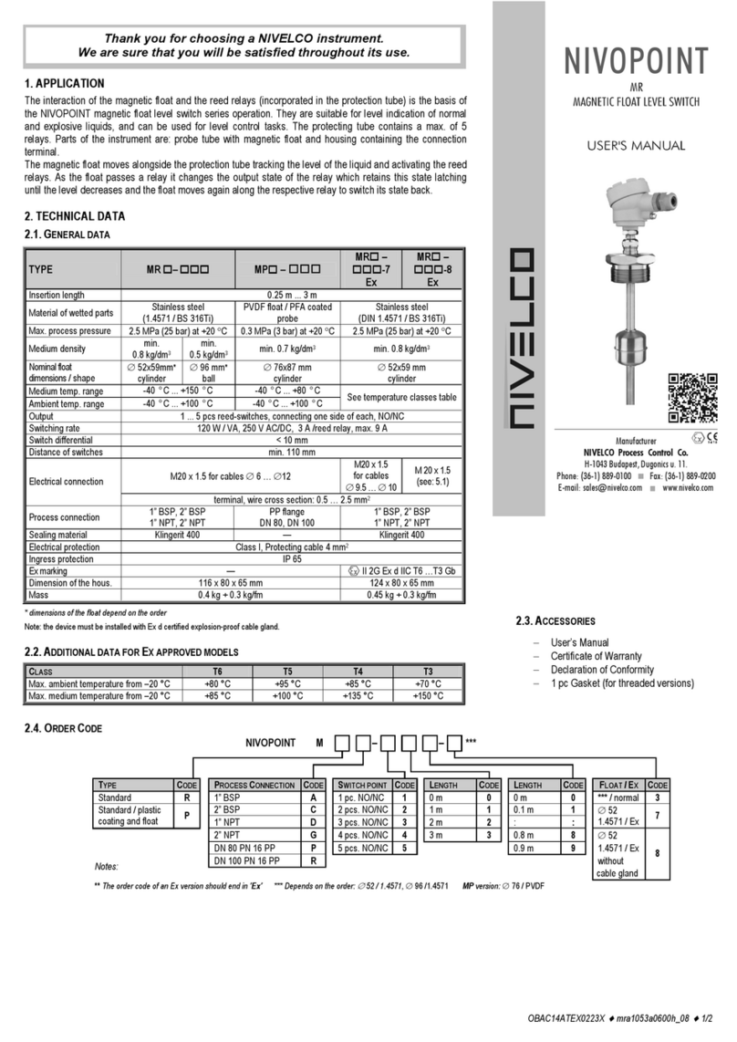
NIVELCO NIVOPOINT MR Series User manual

NIVELCO

NIVELCO NIVOPOINT MR Series User manual

NIVELCO NIVOSWITCH R-400 Series User manual

NIVELCO

NIVELCO NIVOSWITCH R-400 Series User manual

NIVELCO NIVOMAG MK-21 Series User manual

NIVELCO

NIVELCO NIVOMAG MK-21 Series User manual

NIVELCO NIVOSWITCH R-2 Series User manual

NIVELCO

NIVELCO NIVOSWITCH R-2 Series User manual

NIVELCO NIVOSWITCH R-400 User manual

NIVELCO

NIVELCO NIVOSWITCH R-400 User manual

NIVELCO NIVOPOINT User manual

NIVELCO

NIVELCO NIVOPOINT User manual

NIVELCO NIVOFLIP MAK-100 Series User manual

NIVELCO

NIVELCO NIVOFLIP MAK-100 Series User manual

NIVELCO NIPRESS DK-500 Assembly instructions

NIVELCO

NIVELCO NIPRESS DK-500 Assembly instructions

NIVELCO MR Series User manual

NIVELCO

NIVELCO MR Series User manual

NIVELCO NIVOSWITCH R-400 Series User manual

NIVELCO

NIVELCO NIVOSWITCH R-400 Series User manual

Popular Switch manuals by other brands

SMC Networks SMC6224M Technical specifications

SMC Networks

SMC Networks SMC6224M Technical specifications

Aeotec ZWA003-S operating manual

Aeotec

Aeotec ZWA003-S operating manual

TRENDnet TK-209i Quick installation guide

TRENDnet

TRENDnet TK-209i Quick installation guide

Planet FGSW-2022VHP user manual

Planet

Planet FGSW-2022VHP user manual

Avocent AutoView 2000  AV2000BC AV2000BC Installer/user guide

Avocent

Avocent AutoView 2000 AV2000BC AV2000BC Installer/user guide

Moxa Technologies PT-7728 Series user manual

Moxa Technologies

Moxa Technologies PT-7728 Series user manual

Intos Electronic inLine 35392I operating instructions

Intos Electronic

Intos Electronic inLine 35392I operating instructions

Cisco Catalyst 3560-X-24T Technical specifications

Cisco

Cisco Catalyst 3560-X-24T Technical specifications

Asante IntraCore IC3648 Specifications

Asante

Asante IntraCore IC3648 Specifications

Siemens SIRIUS 3SE7310-1AE Series Original operating instructions

Siemens

Siemens SIRIUS 3SE7310-1AE Series Original operating instructions

Edge-Core DCS520 quick start guide

Edge-Core

Edge-Core DCS520 quick start guide

RGBLE S00203 user manual

RGBLE

RGBLE S00203 user manual

Thrustmaster FLIGHT SIMULATOR X quick guide

Thrustmaster

Thrustmaster FLIGHT SIMULATOR X quick guide

Southwire SURGE GUARD 41390 RVC troubleshooting guide

Southwire

Southwire SURGE GUARD 41390 RVC troubleshooting guide

Buhler Nivotemp NT 61 Brief instructions

Buhler

Buhler Nivotemp NT 61 Brief instructions

Kramer VS-41HDCP user manual

Kramer

Kramer VS-41HDCP user manual

Techly IDATA AU-270 user manual

Techly

Techly IDATA AU-270 user manual

Belkin F1U109 user manual

Belkin

Belkin F1U109 user manual

manuals.online logo
manuals.online logoBrands
  • About & Mission
  • Contact us
  • Privacy Policy
  • Terms and Conditions

Copyright 2025 Manuals.Online. All Rights Reserved.

Thank you for choosing a NIVELCO instrument
We are sure that you will be satisfied with it throughout its use
1. OPERATION
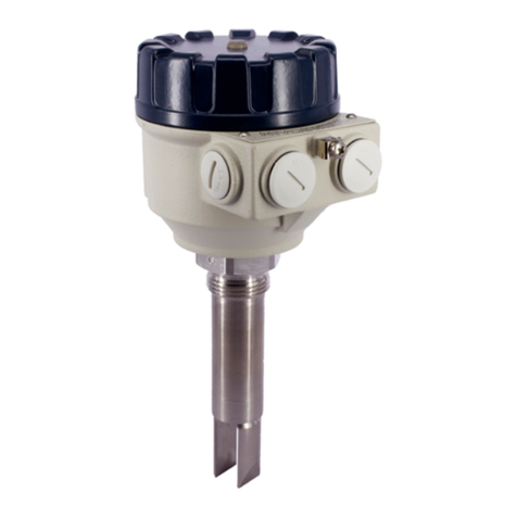
The NIVOSWITCH is a mechanical resonance system; excited, and kept in resonance by an electronic circuitry.
The process medium, when reaching the tines of vibration fork, modifies the vibration. This variation is sensed by an
electronic circuit, which, on the elapse of the delay time, actuates the output circuit. The unit has SPDT relay output.
A virtual DPDT relay feature is achieved through an optional second relay.
2. TECHNICAL DATA
Model R-400 R-500
Wetted parts St.st. 1.4571 (X 6 CrNiMoTi 17122) or ECTFE (Halar) coated st.st.
Process connection According to the order code
Housing material Aluminium: Powder paint coated Plastic: PBT fibre-glass reinforced,
flame-retardant (DuPont)
Medium -40 °C to +130 °C - PP flange: -20 °C to +90 °C
ECTFE coated st.st. flange: -40 °C to +120 °C, for Derating see diagrams
Temperature ranges
Ambient -30 °C to +70 °C
Maximum pressure 40 bar / - PP flange: 6 bar, for Derating see diagrams
Probe length 69 to 3000 mm
Liquids ≥0.7 kg/dm3
Minimum medium density Solids* ≥0.05 kg/dm3
Maximum liquid viscosity ≤10000 mm2/s (cSt)
When immersed ≤0.5 sec
≤1 sec at high density setting ( ≥0.5 kg/dm3)
Response time When free ≤2 sec at low density setting ( <0.5 kg/dm3)
Operation mode indicator Bi-colour LED
High/low adjustment Switch selectable
Densityy adjustment Switch selectable
Output Up to 2 SPDT relays
Relay1: 250 V AC, 8 A, AC 1 Relay 2: 250 V AC, 6A, AC 1
Electric connections 2 x Pg16 for ∅8 to 15 mm cables (0.75 to 2.5 mm2wire cross section)
Supply voltage 20 ... 255 V AC and 20 ... 60 V DC
Consumption AC: 1.2 … 17 VA ; DC: < 3 W
Electrical protection Class I.
Ingress protection IP 67 (NEMA 6)
Weight 1.3 kg + 1.2 kg/m 0.95 kg + 1.2 kg/m
* Please note, that the temperature difference the between inner and outer surface of ECTFE coated flanges must not exceed 60
°
C.
If necessary, insulate outer surface of flange.
USER’S MANUAL
Manufacturer
NIVELCO Process Control Co.
H-1043 Budapest, Dugonics u. 11.
Phone: (36-1) 369-7575 ♦Fax: (36-1) 369-8585
E-mail: [email protected] http://www.nivelco.com
2.1 ACESSORIES
1 x User’s manual 1 x sealing 2 mm thick made of KLINGER OILIT (for BSP 1” process connection only)
1 x Warranty Card 2 pcs. Plug-in type, 3-pole terminal block
2 x Pg 16 cable gland (2 pcs. Plug-in type, 3-pole terminal block in case of 2 relay output)
2.2 ORDER CODE
NIVOSWITCH R - -
Fork Code Connections Code Housing Code Length Code Output Code
ECTFE coated D 1” BSP thread M Alu.cast 4 Short (69 mm)* 00 1 Relay 0
Standard F 1” NPT thread P Plastic 5 Standard (125 mm) 01 2 Relay A
DIN DN50PN40 st.st flange** G 0.2 to 3 m 02…30
2” ANSI st.st. flange** B
50A JIS st.st flange** K
DIN DN50 PN16 PP flange** F
2” ANSI PP flange** A * The short versions are not applicable for solids
50A JIS PP flange** J
2.3 DIMENSIONS 2.4 Derating DIAGRAMS 2.5 RESPONSE TIME - MEDIUM VISCOSITY
Short model
2 x Pg 16
2 x NPT 1/2"
BSP 1"
NPT 1"
89
S=41
69111
Standard model
89
2 x Pg 16
2 x NPT 1/2"
BSP 1"
NPT 1" S=41
111
125
28
∅
Pipe extended model
89
2 x Pg 16
2 x NPT 1/2"
BSP 1"
NPT 1" 28
∅
S=41
111
0,3...3m
for all models (except PP flanged)
for models with Polypropylene flange
0
5
10
15
20
25
30
35
0 2000 4000 6000 8000 10000
fullyimmersed
halfimmersed
onlytheflatpartofthetinesimmersed
Kinematic viscosit
y
[cSt
]
Response time
t
[
sec
]
The test was performed using
silicone oils with different viscosity
ν
Response time (when getting free) versus medium viscosity
3. INSTALLATION
Prevent the device from any mechanical damage.
For positioning the fork-tines, use the marking on the hexagonal neck.
MARK
- Use a TEFLON (PTFE) tape to aid the position-
ing of the fork-tine.
- If the fork-tine position is irrelevant, use the
provided sealing ring
Do not use the housing, to screw the device into the process connection. Do it by
means of the sw = 41 mm hexagonal neck.
After screwing tight the device, the housing can be rotated (max. 300°), to adjust the
cable outlets to the required position.
Installation on liquids
In applications on liquids with
−low viscosity (without risk of material
remaining on the fork-tines) any of the
mounting shown beside is possible,
−high viscosity (due to risk of material
remaining on the fork-tines) only vertical
(top) mounting can be suggested.
In applications with side mounting take care
of the positioning mark.
Installation Options
Mounting threaded versions Critical distances (xmin= 5 mm)
Mountings to be avoided in case of
highly viscous liquids
Mounting in pipe fork-tines must be parallel to
the direction of flow
Installation on light, free flowing solids*
Vertical (top) mounting is the recommended mounting position. Side mounting is recom-
mended only where the fork-tines are easily freed from the process medium (ex.: through
gravity). In case of side mounting, the NIVOSWITCH must be mounted with the fork-tines
standing vertically (look for the positioning marks).
The short versions are not appli-
cable for solids
When determining the mounting
location, take into account the
caving or arching of the material
in the tank. It might be necessary
to install the device at an offset
level position relative to the
switching level actually required
Protect the probe from downfalling material !
Fork-tines should not be exposed to mechanical load.
SWITCHING POINT, SWITCH DIFFERENTIAL
(Values are for water at 25 °C)
Liquids: switching point as well as the switch differential slightly depends on liquid
density and mounting position.
Solids: switching point as well as the switch differential slightly depends on
material features and mounting position
4. ELECTRICAL CONNECTIONS
Use 8 ... 15 mm outer diameter circular cables, and tighten cable glands as well as
housing cover after installation, to ensure an IP67 sealing.
For grounding the unit, either use the grounding screw terminal on the outside of the
housing or use the internal grounding screw terminal. AC with DC, or low voltage with line
cables must not be led in a common duct.
L1+
123
NPT 1/2"
6A/AC1
250VAC
8A/A C1
NPT 1/2"
Pg 16 Pg 16
Grounding
Output
Mains
Density Fail safe
mode
L1
(
+
)
789
456
23
7456 89
Status LED
Relay 1
Relay 2
250VAC
8A/AC1
5. ADJUSTMENT
Suggested DENSITY switch settings are listed in the table below.
Liquids HIGH
LOW ρ< 0,5 kg/dm3
Free flowing solids
HIGH ρ≥0,5 kg/dm3
Before installing the unit, it is advisable to try operation on a small sample of the
product. Do not set a lower density than necessary, since because of greater sensitivity
this may result in indicating even small residues of material adhering to the probe.
OPERATING DIAGRAM
Power
supply Fork Fail safe
mode
Status
LED Output
HIGH RED
45 6 7 8 9
De-energised
Immersed LOW GREEN
45 6 78 9
Energised
HIGH GREEN
45 6 78 9
Energised
Yes
Free LOW RED
45 6 78 9
De-energised
No
Free
or
immersed
HIGH
or
LOW
NOT
LIT 45 6 78 9
De-energised
6. MAINTENANCE
The NIVOSWITCH does not require maintenance on a regular basis. In some instances,
however, the vibrating section may need to be cleaned from the deposited material. This
must be carried out carefully.
7. STORAGE CONDITIONS
Ambient temperature: -25 to +60 °C
Relative humidity: max. 98%
8. WARRANTY
We provide a warranty for the period of 2 (two) years.
All repairs under guarantee are performed in the Manufacturer's premises; the costs of
dismantling, reinstalling or transport are borne by the Customer.
Claims for guarantee are not valid in respect of failures due to abnormal usage, break-
age, disaster, or incompetent installation or usage.
rfm4000a0600h_02
September, 2001
Nivelco reserves the right to change technical specifications without notice.