Interface 9860 User manual

Model 9860
Digital Indicator
Issue: 13-76 Revision
User Manual
www.interfaceforce.com
Model 9860
Digital Indicator
Issue: 13-76 Revision
User Manual
www.interfaceforce.com

Description
The Model 9860 is a TEDS IEEE 1451.4 compliant, enhanced performance, microprocessor-based indicator
capable of interfacing directly to a low level strain gage load cell transducer . The 9860 provides (3) user
selectable calibration modes and (1) factory calibration mode. Consult Interface before accessing the
fact ory calibration mode.
1. CAL1 :Manual entry of zero and calibration values using a live or simulated transducer input.
2. CAL2 : Allows calibration to a specic non-TEDS transducer, when the MAXIMUM FORCE and
MAXIMUM ELECTRI CAL values (mV/V) , of that specic transducer are known.
3. TEDS : The 9860 automatically calibrates itself, when power is applied, if connected to a TEDS
transducer. It must rst sense a TEDS connection and then successfully read the TEDS template
#33 data stored in a one- wire DS2344 or similar microc hip on a congured transducer . This
calibration mode overrides any previously stored calibration.
An internal, high gai n, ful ly-dierential amplier and a 16-bit analog -to-digital converter combine to
accurately digitize the i nput signal. This signal is ltered by a 1kHz analog lter. An additional, smart
digital lter, with user selectable sample size and lter window (band), allows optimization for specic
operating conditions, trading o depth of ltering and step change tracking. U nique, dual auto-calibrated
±10Vdc a nd 4-20mA real time analog outputs are standard. A RS232 interface provides facilities to
continuously read data communicate command and query operating modes and parameters. A powerful 8-
bit microprocessor utilizes a Real Time Operating System (RTOS) to provide seamless control of display,
communications and mathematical computations.
A TEDS status indicator provides the information on the TEDS conguration of the input. See table for
TEDS indicator description.
A precision 10Vdc @ 120mA, short circuit protected, transducer excitation supply is also provided.
A front panel RCAL switch provides a convenient feature for checking calibration. TARE and CALIBRATION
are easily performed via front panel pushbuttons.
Installation and Wiring
INSTALLATION
The Model 9860 enclosure is designated for panel mounting in a 1/8 DIN cutout. The cutout dim ensions
are shown below.
84928 - 9860 Manual 13-76B_8.5x5.5.indd 2 6/12/18 4:10 PM
Description
The Model 9860 is a TEDS IEEE 1451.4 compliant, enhanced performance, microprocessor-based indicator
capable of interfacing directly to a low level strain gage load cell transducer . The 9860 provides (3) user
selectable calibration modes and (1) factory calibration mode. Consult Interface before accessing the
fact ory calibration mode.
1. CAL1 : Manual entry of zero and calibration values using a live or simulated transducer input.
2. CAL2 : Allows calibration to a specic non-TEDS transducer, when the MAXIMUM FORCE and
MAXIMUM ELECTRI CAL values (mV/V) , of that specic transducer are known.
3. TEDS : The 9860 automatically calibrates itself, when power is applied, if connected to a TEDS
transducer. It must rst sense a TEDS connection and then successfully read the TEDS template
#33 data stored in a one- wire DS2344 or similar microc hip on a congured transducer . This
calibration mode overrides any previously stored calibration.
An internal, high gai n, ful ly-dierential amplier and a 16-bit analog -to-digital converter combine to
accurately digitize the i nput signal. This signal is ltered by a 1kHz analog lter. An additional, smart
digital lter, with user selectable sample size and lter window (band), allows optimization for specic
operating conditions, trading o depth of ltering and step change tracking. U nique, dual auto-calibrated
±10Vdc a nd 4-20mA real time analog outputs are standard. A RS232 interface provides facilities to
continuously read data communicate command and query operating modes and parameters. A powerful 8-
bit microprocessor utilizes a Real Time Operating System (RTOS) to provide seamless control of display,
communications and mathematical computations.
A TEDS status indicator provides the information on the TEDS conguration of the input. See table for
TEDS indicator description.
A precision 10Vdc @ 120mA, short circuit protected, transducer excitation supply is also provided.
A front panel RCAL switch provides a convenient feature for checking calibration. TARE and CALIBRATION
are easily performed via front panel pushbuttons.
Installation and Wiring
INSTALLATION
The Model 9860 enclosure is designated for panel mounting in a 1/8 DIN cutout. The cutout dim ensions
are shown below.
In
ORDER TOLL -FREE 800.947.5598
2
Description
The Model 9860 is a TEDS IEEE 1451.4 compliant, enhanced performance, microprocessor-based indicator
capable of interfacing directly to a low level strain gage load cell transducer . The 9860 provides (3) user
selectable calibration modes and (1) factory calibration mode. Consult Interface before accessing the
fact ory calibration mode.
1. CAL1 : Manual entry of zero and calibration values using a live or simulated transducer input.
2. CAL2 : Allows calibration to a specic non-TEDS transducer, when the MAXIMUM FORCE and
MAXIMUM ELECTRI CAL values (mV/V) , of that specic transducer are known.
3. TEDS : The 9860 automatically calibrates itself, when power is applied, if connected to a TEDS
transducer. It must rst sense a TEDS connection and then successfully read the TEDS template
#33 data stored in a one- wire DS2344 or similar microc hip on a congured transducer . This
calibration mode overrides any previously stored calibration.
An internal, high gai n, ful ly-dierential amplier and a 16-bit analog -to-digital converter combine to
accurately digitize the i nput signal. This signal is ltered by a 1kHz analog lter. An additional, smart
digital lter, with user selectable sample size and lter window (band), allows optimization for specic
operating conditions, trading o depth of ltering and step change tracking. U nique, dual auto-calibrated
±10Vdc a nd 4-20mA real time analog outputs are standard. A RS232 interface provides facilities to
continuously read data communicate command and query operating modes and parameters. A powerful 8-
bit microprocessor utilizes a Real Time Operating System (RTOS) to provide seamless control of display,
communications and mathematical computations.
A TEDS status indicator provides the information on the TEDS conguration of the input. See table for
TEDS indicator description.
A precision 10Vdc @ 120mA, short circuit protected, transducer excitation supply is also provided.
A front panel RCAL switch provides a convenient feature for checking calibration. TARE and CALIBRATION
are easily performed via front panel pushbuttons.
Installation and Wiring
INSTALLATION
The Model 9860 enclosure is designated for panel mounting in a 1/8 DIN cutout. The cutout dim ensions
are shown below.

3
In
ORDER TOLL -FREE 800.947.5598
To panel mount the 9860, perform the following steps.
1. Rotate the four pawl screws (outside screws in each corner) several turns counter-clockwise to
retract the pawls. Make sure the pawls retract enough to clear the back of the mounting panel.
The pawls may be retracted to accommodate panel thicknesses up to 0.25 inches (6.35mm).
2. Insert the instrument into the panel cutout.
3. Position the pawls so that their elongated dimension overlaps the panel cutout , and then tighten the
screws. Do not over-tighten!
4. Installation complete.
WIRING
Reference Figures 3 and 4 for TRANSDUCER and I/O wiring information. Power is applied with a 3- prong
AC power cord. The instrument is protected by a 250V, 315mA 5mm fuse. The fuse holder is an integral
part of the input power connector. A spare fuse is provided in the fuse holder.
Figure 1 - Model 9860 Front Panel View
Figure 2. Model 9860 Rear Panel View
3
To panel mount the 9860, perform the following steps.
1. Rotate the four pawl screws (outside screws in each corner) several turns counter-clockwise to
retract the pawls. Make sure the pawls retract enough to clear the back of the mounting panel.
The pawls may be retracted to accommodate panel thicknesses up to 0.25 inches (6.35mm).
2. Insert the instrument into the panel cutout.
3. Position the pawls so that their elongated dimension overlaps the panel cutout , and then tighten the
screws. Do not over-tighten!
4. Installation complete.
WIRING
Reference Figures 3 and 4 for TRANSDUCER and I/O wiring information. Power is applied with a 3- prong
AC power cord. The instrument is protected by a 250V, 315mA 5mm fuse. The fuse holder is an integral
part of the input power connector. A spare fuse is provided in the fuse holder.
Figure 1 - Model 9860 Front Panel View
Figure 2. Model 9860 Rear Panel View

Figure3. Transducer Wiring –NOTE: for optimum performance cable shield should be connected to the
instrument chassis.
Figure 4. I/O Wiring

direction. The beauty of open collector outputs is, since these outputs are oating, they can be used
with any voltage source up to 50 VDC. In this way you can match the output voltage level of the 9860 to
any external equipment input be it 2.5 VDC or 48 VDC.
See Appendix H for further details.
Input range and analog output adjustm ent s ettings
Front Panel Switch and Function Denitions
SWITCH DEFINITIONS
Mode S election Switch
Mode is used to cycle through the various programmable functions of the 9860. The sequence is as
follows. The designators, in { }, identify text that will be displayed. The settable values are shown in ( )
Note: After a setting has been changed the mode switch must be pressed to save the changed value.
Factory Default Settings
Full Scale CAL Switch Disabled {CAL O } or Enabled {CAL On }
CAL O
Filter Value {FILtEr } (00 to 99)
99
Filter Window Value {bAnd} (001 to 999)
999
Decimal Point {dP} (x.xxxx, xx.xxx, xxx.xx, xxxx.x, xxxxx)
xxxxx
Calibration Number {CAL} (00001 to +/ -99999)
10000
Full Scale Number {FS} (00001 to +/ -99999)
10000
Setpoint 1 to Monitor {SP-} (Instantaneous, Peak, Valley, Peak -Valley)
Instantaneous
Setpoint 1 to be {SP1} high setpoint (HI ) or low setpoint (LO)
High Setpoint
Set Setpoint 1 Value (Set SP) (00000 to +/ -99999)
99999
Setpoint 2 , 3 and 4 use the same format
Hysteresis for Low Se tpoints {HL} (000 to 200)
000
Hysteresis for High Setpoints {HH}
000
While i n the Mode Selection sequence, the indicator is no longer monitoring the input signal. To exit
Depress MODE once to save any changed settings , and then RESET to return to norma l operation .
Decrement or Tare Switch
This switch serves two functions, depending on the present status of MODE. If the meter is in the Mode
Selection sequence, this switch decrements the ashing digit.
If the meter is in its normal operating mode, it becomes the TARE switch. Depressing TARE will
automatically zero the readout, illuminate the TARE LED and zero the analog output. Depressing and
holding TARE depressed for approximately 3 seconds will UNTARE the readout and extinguish the TARE
LED. TAR ING is accomplished by storing the reading prior to TARING and subtracting this value from all
subsequent readings.
Increment or Cal Switch
This switch also serves two functions, depending on the present status of MODE. If the instrument is in the
Mode Selection sequence, this switch functions in the following manner .
1. In the CAL selection mode, it selects the calibration mode: CAL OFF, CAL1 or CAL2.
2. In the parameter update mode, it will increment the ashing digit or toggle status.
If the instrument i s in its op erating mode and waiting for a CAL1 calibration to be performed this switch
will input zero and calibration values. Be sure to read Appendix B & C before using this switch.
Step Switch
When the instrument is in the Mode Selection sequence, this switch allows the user to cycle through the
digits. Used In conjunction with and it allows rapid updating of numerical values.
Display Switch
In operating mode this switch cycles the readout to display:
Annunciator(s) Illuminat ed
Peak- Valley PK and VAL
Peak PK
Valley VAL
Instantaneous readings None
Reset or Exit Switch
This switch also serves two functions, depending on the present status of MODE. If the instrument is in the
Mode selection sequence, this switch is used to Exit this sequence and return to the normal display mode.
Any selections made during the Mode Selection sequence, prior to that selected just before exiting, will
be saved and remembered in non-volatile memory.
If the instrument is in the normal (instantaneous) display mode the
reset switch will reset the stored Peak, Valley and Peak-Valley
readings to the current Instantaneous value.
RCAL Switch
This switch activates a reed relay, which places a xed resistor
across -Sig and -Vexc for a positive RCAL reading, o r across -Sig and
+Vexc for a negative RCAL reading. Removing the back panel of the
instrument case will allow access to the RCAL resistor and settings
jumper. The jumper on P2 determines the polarity of the RCAL
output with position 1 for negative and position 2 for positive. The
RCAL resistor can be changed if desired; a 10ppm tempco resistor is
recommended.
Figure 8 –Location of Rcal direction Jumpers and Rcal resistor.

Menu Function Denitions
Filter Value (FILtEr) (00 to 99)
The 9860 uses a lter based on a digital averaging technique where N samples are arithmetically
averaged.
Subsequent averages subtract the oldest reading and add the newest reading. The number of readings is
equal to the value of (FILtEr ). The default lter setting is 99.
Higher (FIL tEr) values produce stronger ltering with a slower resp onse. Maximum Filtering=99.
Filter Band (bAnd) (001 to 999)
To permit a heavy lter and still have fast response to a step input change, the lter operates only inside
a stable Band. If two consecutive conversions have a dierence greater than the bAnd value , the
instrument temporarily shuts o the lter, permitting maximum response. When the dierence is again
within the bAnd value , the lter returns to the selected (FILtEr) value. The bAnd number corresponds
roughly to the raw ADC counts. The factory default is bAnd = 999 . See appendix A for lter details.
Decimal Point (dP) (x.xxxx, xx.xxx, xxx.xx, xxxx.x, xxxxx)
dP allows selection of decimal point locations for display. The locations selectable are shown in ( ) above.
The Increment and Decrement switches are used to shift decimal places.
Calibration Number (CAL) (00001 to 99,999)
In the ON1mode, the (CAL) is equal to the desired reading corresponding to the calibration load, whet her
the load is Actual, simulated or from RCAL. This value is in user units (lbf or N for example). The number
is entered prior to performing the calibration. A Full Scale Number must also be entered to scale the
ANALOG output. See ANALOG OUPUTS for a det ailed description.
In the ON2mode, (CAL) is equal to the FULL SCALE value of the transducer. The full scale value will be
Automatically set to the Calibration Number.
In t he TEDS mode, the (CAL) value is automatically set, by the instrument, to the (FS) value read from the
Transducer. See CALIBRATION INSTRUCTIONS for more details.
Scale
In the calibration ON2mode, the SCALE value is equal to the transducer MAXIMUM OUTPUT value in mV/V
as found on a calibration certicate. In this mode values are entered manually similar to what would be
automatically uploaded from a TEDS transducer. SCALE is only changeable in the ON2 mode.
Full Scale Number (FS) (00001 - to +/- 99999)
The (FS) represents the value at which the ANALOG output is at full value (10v or 20mA). In the ON1
calibration mode this value can be altered to t the needs of the user. For example if using a 10000lbf
load cell but the user is only interested in the output up to 5000lbf the FS can be set for 5000 for a 10V
output at 5000lbf. The display would still read values up to and over 10000lbf. This allows for a higher
analog output resolution (lower noise) over a smaller input range of interest.
In the ON2 mode, the (FS) value is equal to the user entered CAL value. (FS) is automatically updated
when the CAL value is updated. It cannot be altered by the user.
In the TEDS mode, (FS) is used to indicate the full scale value of a TEDS transducer. (FS) cannot be
changed in this mode.

Set poin t to Monitor
This function allows Setpoints 1-4 to monitor the instantaneous, peak, valley, or peak minus valley
displays. The Increment or Decrement switches are used to cycle through the various displays. To signify
which display is being monitored, the least Signicant 7 -segment display will be illuminated as shown
below.
Setpoint to be (SP HI) {SP HI, SP LO}
This allows Setpoints 1-4 to be a High or Low Setpoint. The Increment or Decrement switches are used to
cycle through the HI or LO selection.
A High Setpoint is disabled when the compared value is less than the Setpoint value. The High Setpoint is
enabled when the compared value is equal to or greater than the Setpoint value.
A Low Setpoint is disabled when the compared value is greater than the Setpoint value. The Low Setpoint
turns on when the compared value is equal to or less than the Setpoint value.
Set Setpoint Value (Set SP) {00000 to +/- 99,999}
Setpoints 1-4 can be set for any value from 00000 to +/-99,999. This value along with the previous
selection of SP HI or SP LO determines when the optically isolated open-collector output transistors are
activated and the relevant SP enunciator is illuminated.
Hysteresis Low (HL) {000 to 200}
HL is the hysteresis value for all Setpoints set to SP LO. HL determines the value the displayed reading
must exceed the Setpoint value by before deactivating their respective open- collector output(s).
Hysteresis High (hh) {000 to 200}
HH is the hysteresis value for all Setpoints set to SP HI. HH determines the value the displayed reading
must get below the Setpoint value by before deactivating their respective open-collector output(s).
See appendix D for programming instructions.
Operating Instructions
Turn-On Instructions
Reference Figures 3 and 4 for proper input and output signal wiring.
1. Apply power to the instrument.
2. Verify the instruments readout momentarily displays a relx.xr rmware version number.
Program Instructions
(4) front panel switches allow the user to program Cal Mode, LSD, Decimal Point (dP) , Filter
9
Value, Filter Window (bAnd), Calibration Number (CAL), Scale, Full Scale Number (FS), Setpoint to Monitor
(SP-
rate values.
To exit the MODE sequence without enabling a change, depress the RESET switch. All entries prior to
RESET, not
Calibration Instructions
The Model 9860 provides three (3) calibration modes. In the
entry modes are disabled.

ORDER TOLL -FREE 800.947.5598
Value, Filter Window (bAnd), Calibration Number (CAL), Scale, Full Scale Number (FS), Setpoint to Monitor
Setpoint to be (SP HI), Setpoint value (Set SP), Hysteresis Low (HL), Hysteresis High (HH) and Baud
rate values.
To exit the MODE sequence without enabling a change, depress the RESET switch. All entries prior to
RESET, not including the function active at RESET, will be updated.
Calibration Instructions
The Model 9860 provides three (3) calibration modes. In the OFF state, the CAL1 and CAL2 manual
entry modes are disabled.
CAL1
CAL2
TEDS
Auto calibration when connecting to a TEDS, Template #33 congured transducer, with TEDS
sensing pin. In the TEDS AUTO MODE, the unit self calibrates to the MAXIMUM FORCE and
MAXIMUM OUTPUT values found in the TEDS transducer .The 9860 updates the CAL value to the
MAXIMUM FORCE value read from the TEDS template.
Calibration is automatic if the 9860 senses a TEDS connection and is able to read the TEDS
microchip imbedded in the transducer. Simply connect the TEDS transducer to the 9860 and apply
power. The displayed reading and analog outputs are automatically calibrated.
The TEDS parameters are stored in non-volatile memory. When the TEDS transducer is
disconnected and reconnected or a dierent TEDS transducer, with sensing pin, is connected, the
unit automatically self calibrates, without the need for power recycling. The TEDS LED indicates
the state of the TEDS connection. See TEDS INDICATOR AND BLINK CONFIGURATIONS for detail
descr iption. See appendix B & C for programming instructions.
TEDS Indicator LED behavior
The following TABLE describes the functionality of the red TEDS led. The led is ON when a
combination of TEDS SENSE switch or TEDS ROM is detected. The particular comb ination is
indicated by the led activity. If the TEDS SENSE switch and valid TEDS ROM data are detected, the
led is ON steady. If TEDS SENSE switch is detected and valid TEDS ROM is not detected, the l ed
To exit the MODE sequence without enabling a change, depress the RESET switch. All entries prior to
RESET, not including the function active at RESET, will be updated.
Calibration Instructions
The Model 9860 provides three (3) calibration modes. In the OFF state, the CAL1 and CAL2 manual
entry modes are disabled.
1. CAL1
2. CAL2
3. TEDS
Auto calibration when connecting to a TEDS, Template #33 congured transducer, with TEDS
sensing pin. In the TEDS AUTO MODE, the unit self calibrates to the MAXIMUM FORCE and
MAXIMUM OUTPUT values found in the TEDS transducer .The 9860 updates the CAL value to the
MAXIMUM FORCE value read from the TEDS template.
Calibration is automatic if the 9860 senses a TEDS connection and is able to read the TEDS
microchip imbedded in the transducer. Simply connect the TEDS transducer to the 9860 and apply
power. The displayed reading and analog outputs are automatically calibrated.
The TEDS parameters are stored in non-volatile memory. When the TEDS transducer is
disconnected and reconnected or a dierent TEDS transducer, with sensing pin, is connected, the
unit automatically self calibrates, without the need for power recycling. The TEDS LED indicates
the state of the TEDS connection. See TEDS INDICATOR AND BLINK CONFIGURATIONS for detail
descr iption. See appendix B & C for programming instructions.
TEDS Indicator LED behavior
The following TABLE describes the functionality of the red TEDS led. The led is ON when a
combination of TEDS SENSE switch or TEDS ROM is detected. The particular comb ination is
indicated by the led activity. If the TEDS SENSE switch and valid TEDS ROM data are detected, the
led is ON steady. If TEDS SENSE switch is detected and valid TEDS ROM is not detected, the l ed
To exit the MODE sequence without enabling a change, depress the RESET switch. All entries prior to
RESET, notincluding the function active at RESET, will be updated.
Calibration Instructions
The Model 9860 provides three (3) calibration modes. In the OFF state, the CAL1 and CAL2 manual
entry modes are disabled.
1. CAL1
2. CAL2
3. TEDS
calibration when connecting to a TEDS, Template #33 congured transducer, with TEDS
sensing pin. In the TEDS AUTO MODE, the unit self calibrates to the MAXIMUM FORCE and
MAXIMUM OUTPUT values found in the TEDS transducer .The 9860 updates the CAL value to the
MAXIMUM FORCE value read from the TEDS template.
Calibration is automatic if the 9860 senses a TEDS connection and is able to read the TEDS
microchip imbedded in the transducer. Simply connect the TEDS transducer to the 9860 and apply
power. The displayed reading and analog outputs are automatically calibrated.
The TEDS parameters are stored in non-volatile memory. When the TEDS transducer is
disconnected and reconnected or a dierent TEDS transducer, with sensing pin, is connected, the
unit automatically self calibrates, without the need for power recycling. The TEDS LED indicates
the state of the TEDS connection. See TEDS INDICATOR AND BLINK CONFIGURATIONS for detail
descr iption. See appendix B & C for programming instructions.
TEDS Indicator LED behavior
The following TABLE describes the functionality of the red TEDS led. The led is ON when a
combination of TEDS SENSE switch or TEDS ROM is detected. The particular comb ination is
indicated by the led activity. If the TEDS SENSE switch and valid TEDS ROM data are detected, the
led is ON steady. If TEDS SENSE switch is detected and valid TEDS ROM is not detected, the l ed

blinks FAST. If TEDS SENSE switch is not detected and valid TEDS ROM is detected, the led blinks
SLOW. A blink condition indicates a problematic situation.
If both TEDS SENSE SWITCH and valid TEDS ROM are not detected, the TEDS led is OFF. The
instrument is in one of the other calibration modes: Eith er OFF, ON1 or ON2.
Excitation Supply
The EXC output is short circuit protected from shorts to ground. When a short to ground is detected,
the output current is reduced to prevent damage. In most cases, removing the short will cause the
output to recover. If removing the short fails to cause recovery, recycle the AC line power.
Analog Outputs
The 9 860 provides auto-calibrating ± 10Vdc and 4 -20mA analog output signa ls. The maximum output of
10 volts or 20mA corresponds to the FULL SCALE value. Both the 10V output and the 4-20mA outputs
are automatically scaled by (FS). (FS) = the display value that corresponds to the full scale spans of
the outputs, either 10V or 20mA. The ANALOG output is a digitally-scaled, real time, analog ltered
and buered output directly proportional to the input.
Examples:
1. A 9860 reads TEDS capable transducer with a maximum capacity of 10,000 lb. FS will indicate
10000. The actua l load is 4000 lb. The voltage output is +(4000/1 0000)X10=+4 V and
+(4000/10000)x16+4=10.4 mA.
2. A 9860 is in the ON1/OFF mode. The CAL and FS values are 10000 lb and 20000 lb, respectively.
The actual load is 50000 lb. The voltage output is +(5000/2000 0)X10=+2.5 V and
+(5000/20000)x16+4=8.0 mA.
3. A 9860 is in the ON2 mode. The CAL and FS values are 15000 lb. The actual load is 9000 lb. The
voltage
Output is +(9000/15000)X10=+6.0 V and +(9000/15000)x16+4=13.6 mA.
The TARE function operates on the analog output the same as it does on the digital display. The
polarity of the analog output is always the same as the input signal. However, the 4-20 mA output is
unipolar and is linear only with positive input signal s. Signals less than zero are clamped and will
typically generate only 2mA on the 4-20mA output.
Serial RS232 Communications
General Information

11
In
ORDER TOLL -FREE 800.947.5598
2. A 9860 is in the ON1/OFF mode. The CAL and FS values are 10000 lb and 20000 lb, respectively.
The actual load is 50000 lb. The voltage output is +(5000/2000 0)X10=+2.5 V and
+(5000/20000)x16+4=8.0 mA.
3. A 9860 is in the ON2 mode. The CAL and FS values are 15000 lb. The actual load is 9000 lb. The
voltage
Output is +(9000/15000)X10=+6.0 V and +(9000/15000)x16+4=13.6 mA.
The TARE function operates on the analog output the same as it does on the digital display. The
polarity of the analog output is always the same as the input signal. However, the 4-20 mA output is
unipolar and is linear only with positive input signals. Signals less than zero are clamped and will
typically generate only 2mA on the 4-20mA output.
Serial RS232 Communications
General Information
See Figure 4 on page 4 for RS232 connections and wiring information.
See Appendix F for serial commands.
The RS232 port is always active. The data is transmitted in the following format:
One Start Bit;
Eight Data Bits;
No Parity Bit;
One Stop Bit;
Baud rate is set manually through the MODE sequence or via the RS232 port. Available baud rates are:
9600, 19.2k, 38.4k, 57.6k and 115.2k baud. The default baud rate is 115200.
Transmissions to and from the Model 9860 is dened in the following Tables:
<CR> denotes ENTER
XON and XOFF are used to control transmission of a continuous data stream
INPUT, MAX, MIN or MAX-MIN as being displayed, will be transmitted
The data being transmitted can be changed from the front panel SEL switch or by RS232 command
During data transmission, most COMMANDS and QUERYS are functional.
RESET, will function as the front panel switch
The FILTER VALUE and FILTER BAND can be updated and will immediately be implemented
TARE and UNTARE are active
DECIMAL POINT can be altered. CAUTION: changing the DECIMAL POINT will cause the MAX- MIN
Value to be in error. The MAX-MIN value must be RESET after the DECIMAL POINT change.
The LSD can be turned ON and O.
The HYSTERESIS values can be changed.
SETPOINT par ameters can be modied
11
2. A 9860 is in the ON1/OFF mode. The CAL and FS values are 10000 lb and 20000 lb, respectively.
The actual load is 50000 lb. The voltage output is +(5000/2000 0)X10=+2.5 V and
+(5000/20000)x16+4=8.0 mA.
3. A 9860 is in the ON2 mode. The CAL and FS values are 15000 lb. The actual load is 9000 lb. The
voltage
Output is +(9000/15000)X10=+6.0 V and +(9000/15000)x16+4=13.6 mA.
The TARE function operates on the analog output the same as it does on the digital display. The
polarity of the analog output is always the same as the input signal. However, the 4-20 mA output is
unipolar and is linear only with positive input signals. Signals less than zero are clamped and will
typically generate only 2mA on the 4-20mA output.
Serial RS232 Communications
General Information
See Fi gure 4 on page 4 for RS232 connections and wiring information.
See Appendix F for serial commands.
The RS232 port is always active. The data is transmitted in the following format:
One Start Bit;
Eight Data Bits;
No Parity Bit;
One Stop Bit;
Baud rate is set manually through the MODE sequence or via the RS232 port. Available baud rates are:
9600, 19.2k, 38.4k, 57.6k and 115.2k baud. The default baud rate is 115200.
Transmissions to and from the Model 9860 is dened in the following Tables:
<CR> denotes ENTER
XON and XOFF are used to control transmission of a continuous data stream
INPUT, MAX, MIN or MAX-MIN as being displayed, will be transmitted
The data being transmitted can be changed from the front panel SEL switch or by RS232 command
During data transmission, most COMMANDS and QUERYS are functional.
RESET, will function as the front panel switch
The FILTER VALUE and FILTER BAND can be updated and will immediately be implemented
TARE and UNTARE are active
DECIMAL POINT can be altered. CAUTION: changing the DECIMAL POINT will cause the MAX- MIN
Value to be in error. The MAX-MIN value must be RESET after the DECIMAL POINT change.
The LSD can be turned ON and O.
The HYSTERESIS values can be changed.
SETPOINT par ameters can be modied
2. A 9860 is in the ON1/OFF mode. The CAL and FS values are 10000 lb and 20000 lb, respectively.
The actual load is 50000 lb. The voltage output is +(5000/2000 0)X10=+2.5 V and
+(5000/20000)x16+4=8.0 mA.
3. A 9860 is in the ON2 mode. The CAL and FS values are 15000 lb. The actual load is 9000 lb. The
voltage
Output is +(9000/15000)X10=+6.0 V and +(9000/15000)x16+4=13.6 mA.
The TARE function operates on the analog output the same as it does on the digital display. The
polarity of the analog output is always the same as the input signal. However, the 4-20 mA output is
unipolar and is linear only with positive input signals. Signals less than zero are clamped and will
typically generate only 2mA on the 4-20mA output.
Serial RS232 Communications
General Information
See Figure 4 on page 4 for RS232 connections and wiring information.
See Appendix F for serial commands.
The RS232 port is always active. The data is transmitted in the following format:
One Start Bit;
Eight Data Bits;
No Parity Bit;
One Stop Bit;
Baud rate is set manually through the MODE sequence or via the RS232 port. Available baud rates are:
9600, 19.2k, 38.4k, 57.6k and 115.2k baud. The default baud rate is 115200.
Transmissions to and from the Model 9860 is dened in the following Tables:
<CR> denotes ENTER
XON and XOFF are used to control transmission of a continuous data stream
INPUT, MAX, MIN or MAX-MIN as being displayed, will be transmitted
The data being transmitted can be changed from the front panel SEL switch or by RS232 command
During data transmission, most COMMANDS and QUERYS are functional.
RESET, will function as the front panel switch
The FILTER VALUE and FILTER BAND can be updated and will immediately be implemented
TARE and UNTARE are active
DECIMAL POINT can be altered. CAUTION: changing the DECIMAL POINT will cause the MAX- MIN
Value to be in error. The MAX-MIN value must be RESET after the DECIMAL POINT change.
The LSD can be turned ON and O.
The HYSTERESIS values can be changed.
SETPOINT par ameters can be modied

Appendix A
Understanding the 9860 Digital Filter Settings
The 9860 digital lter is implemented as a cumulative moving average lter. It is used to lter the output
of a 16 -bit successive approximation analog- to-digital converter running at a rate of 250 conversions per
second. The lter has (2) user selectable inputs that determine the digital lter settling time and noise
rejection capabilities. The user selectable inputs are Filter (01-99) and Band (000- 999).
Filter (01 -99) Sets the cumulative moving average lter subset size, where i=subset size.
CAi = Xi/i + CAi- 1(i -1/i). Xi is the unltered raw analog -to-digital converter data.
The number of readings averaged is 4x the lter subset size.
Band (00 0-999) Sets the unltered, raw analog- to-digital converter data variation limits. It is used to
determine when the cumulative moving average lter is enabled and when it is
disabled. If the magnitude of the dierence between 2 successive unltered, raw
analog-to-digital converter data is less than the Band, the lter is enabled. If it is
equal to or greater than the Band, the lter is disabled.
When the Band is exceeded, and the lter is disabled, the Instantaneous display of the 9860 is the
unltered, calibrated data from the analog- to-digital converter and is read in approximately 4
milliseconds. This allows the display to follow large changes in display values, peaks or valleys, virtually
instantaneously.
If the readings are within the Band and the Filter is set to 90, the digital lter is basically averaging 360
readings using a weighted moving average. This is done in 4 milliseconds. If the Band is then exceeded, it
would take approximately 360 readings x (4ms/reading) or approximately 1.44 seconds to fully implement
the Filter subset size.
NOTE 1: The digital lter uses the unltered , raw analog -to-digital converter data. The Instantaneous,
Peak (PK) and Valley (VAL) readings are normally ltered, calibrated analog-to-digital converter data,
and with the exception explained above, when 2 successive readings initially exceed the Band.
NOTE 2: The analog output is implemented using the signal input to the 9860. The input signal is
amplied, buered and auto-scaled to the calibrated reading. It is a real time display, not the step
output of a digital- to-analog converter. It is ltered by a 2-pole, 1kHz, Butterworth analog active lter.
13
Appendix B
Calibrating the 9860 using the CAL ON1 calibration method
The CAL ON1 calibration requires one of the following to perform.
The 9860 has (2) input full scale ranges, 25mV and 50mV. Unless otherwise specied, the factory default
is 50mV. To change the full scale range to 25mV, reference the instructions shown in Appendix F.
Exa
precision load cell simulator or known force (weight).
Connect the 9860 to the load cell simulator. Set the simulator to ZERO and apply power to the 9860
Depress the KEY switch, followed by the ENTRY as shown below.

13
In
ORDER TOLL -FREE 800.947.5598
Appendix B
Calibrating the 9860 using the CAL ON1 calibration method
The CAL ON1 calibration requires one of the following to perform.
1. A load cell and calibrated loads.
2. A precision load cell simulator or calibrator.
3. A known readout value for an applied RCAL resistor.
The 9860 has (2) input full scale ranges, 25mV and 50mV. Unless otherwise specied, the factory default
is 50mV. To change the full scale range to 25mV, reference the instructions shown in Appendix F.
mple: Calibrate the 9860 to read 00000 to 10.000 with an input of ZERO and XXmV/V full scale using a
precision load cell simulator or known force (weight).
Connect the 9860 to the load cell simulator. Set the simulator to ZERO and apply power to the 9860 .
Depress the KEY switch, followed by the ENTRY as shown below.
KEY PRESS
ENTRY
9860 DISPLAY
COMMENTS
MODE
C0dE
A prompt to enter code
CAL … OFF
Entry code accepted
or
0n 1
CAL1 active
MODE
LSd … 0n
Least signicant digit active
MODE
dP … blank display
Default setting (no DP)
x.xxxxx
Decimal point shifts I digit to the right
xx.xxxx
DP shifts to the right again
xxx.xxx
And again
MODE
FILtEr … 90
Filter value factory default setting
MODE
bAnd … 500
Filter band factory defau lt
MODE
CAL … xxx.xxx
Last CAL number entry displayed , left most
digit will be ashing
and STEP
010.000
Use entry keys to set CAL number
MODE
SCALE … x.xxxxx
Ignore this reading
MODE
FS … xxx.xxx
Last FS entry displayed
and STEP
010.000
Use entry keys to set FS number
MODE
SP1 -
Ignore this reading
RESET
xxx.xxx
000.000
TARE and CAL LEDs illuminate
Set the simulator to desired full scale or
apply full scale force
Verify the calibration
10.000
Calibration complete
13
Appendix B
Calibrating the 9860 using the CAL ON1 calibration method
The CAL ON1 calibration requires one of the following to perform.
1. A load cell and calibrated loads.
2. A precision load cell simulator or calibrator.
3. A known readout value for an applied RCAL resistor.
KEY PRESS ENTRY 9860 DISPLAY COMMENTS
MODE C0dE A prompt to enter code
CAL … OFF Entry code accepted
or 0n 1 CAL1 active
MODE LSd … 0n Least signicant digit active
MODE dP … blank display Default setting (no DP)
x.xxxxx Decimal point shifts I digit to the right
xx.xxxx DP shifts to the right again
xxx.xxx And again
MODE FILtEr … 90 Filter value factory default setting
MODE bAnd … 500 Filter band factory defau lt
MODE CAL … xxx.xxx
Last CAL number entry displayed , left most
digit will be ashing
and STEP 010.000 Use entry keys to set CAL number
MODE SCALE … x.xxxxx Ignore this reading
MODE FS … xxx.xxx Last FS entry displayed
and STEP 010.000 Use entry keys to set FS number
MODE SP1 - Ignore this reading
RESET xxx.xxx
000.000 TARE and CAL LEDs illuminate
Set the simulator to desired full scale or
apply full scale force
Verify the calibration
10.000 Calibration complete

Appendix C
Calibrating the 9860 using the CAL ON2 calibration method
CAL2: Auto calibration when connecting to a non -TEDS transducer, with known MAXIMUM FORCE and
corresponding MAXIMUM OUTPUT in mV/V. The mV/V values should be found on the transducer
calib ration sheet.
In the CAL2 mode, the MAXIMUM FORCE or CAL value and the MAXIMUM OUTPUT in mV/V or
SCALE values are entered. The 9860 uses these values to auto -calibrate the readout and analog outputs.
ZERO or TARE may be initiated after the CAL2 calibration is completed.
The CAL2 calibration mode does not require a transducer or simulator connection to the 9860.
KEY PRESS ENTRY 9860 DISPLAY COMMENTS
MODE C0dE A prompt to enter code
CAL … OFF Entry code accepted
or 0n 1 Now select CAL2
or 0n 2 CAL2 active
MODE LSd … 0n Least signicant digit active
MODE dP … blank display Default setting (no DP)
x.xxxxx Decimal point shifts I digit to the right
xx.xxxx DP shifts to the right again
xxx.xxx And again
MODE FILtEr … 90 Filte r value factory default setting
MODE bAnd … 500 Filter band factory default
MODE CAL … xxx.xxx
Last CAL number entry displayed, left most
digit will be ashing
and STEP 010.000 Use entry keys to set CAL number
MODE SCALE … x.xxxxx
Enter the mV/V value that corresponds to
the CAL value in the last step
MODE FS … xxx.xxx Last FS entry displayed
and STEP 010.000 Use entry keys to set FS number
MODE SP1 - Ignore this reading
RESET xxx.xxx
000.000 TARE and LED illuminates but not CAL
Set the simulator to desired full scale or
apply full scale force
Verify the calibration
10.000 Calibration complete

Appendix D
Programming s et points
KEY PRESS ENTRY 9860 DISPLAY COMMENTS
MODE C0dE A prompt to enter code
CAL … OFF Entry code accepted
MODE SP1 - Press MODE until setpoint menu
- Monitor Normal, PK, VAL or PK-VAL
MODE SP1 HI or L0 High or Low setpoint?
Select high or low
MODE Set SP then xxx.xxx Will display last SP value
and STEP xxx.xxx Set the desired value
MODE SP2 - Repeat steps to program SP2 – SP4
After the settings for SP4 have been entered there is an opportunity to set the hysteresis for Low and High
setpoints. These values are entered the same as any other numerical value: step selected the digit and the
up and down buttons selected the value of that digit.

Appendix E
Accessing Internal Switches and Potentiometers
To access the internal DIP switch and analog output potentiometer adjustments perform the follow ing.
Remove these 4 screws Remove these 4 screws
Then gently remove the top cover, to expose the DIP switch and analog output gain adjustment pots
DIP SW2 position
Excitation
4
3
2
1
INPUT RANGE
10V
ON
OFF
ON
OFF
50mV
OFF
OFF
OFF
ON
25mV
20mA Adj (R51) 4mA Adj (R54)
Zero Adj (R40) + 10V Adj (R57)

Appendix F
Serial RS232 Queries and Commands
Query/Command
Response
Notes :
[<CTRL>Q]<CR>
XON serial mode
Streams current display values
[<CTRL>S]<CR>
XOFF
Meter to command mode
RS<CR>
Reset Display
Function of front panel RESET button
ZA<CR>
TARE status
Returns 0=UNTARE, 1=TARE
ZA<n><CR>
Functions as TARE button
Sets 0=UN TARE, 1=TARE
Queries and commands that derive from the set up menu
BR<n><CR>
Baud Rate Selection
n=9600, 19200, 38400, 57600 or
115200*
CV<CR>
Cal Value
Will return 6 digit cal value
CV<nnnnnn><CR>
CS<CR>
Cal mV/V for pseudo TEDS
0.0 0nnnnn or n.nnnnE -03 format
CS<nn.nnnn><CR>
DP<CR>
Decimal Point Value
0 to 5
DP<n><CR>
With 0 being no decimal point
FB<CR>
Filter Band Value
000 to 999
FB<nnn><CR>
FV<CR>
Filter Value
00 to 99
FV<nn><CR>
FS<CR>
Fullscale Va lue
999999
FS<nnnnnn><CR>
SF<CR>
Scale factor value
Returns SF in E format
SF<nn.nnnn><CR>
Use 0.00nnnnn or n.nnnnE -03 format
HH<CR>
Hysteresis High Value
00 to 99
HH<nn><CR>
HL<CR>
Hysteresis Low Value
00 to 99
HL<nn><CR>
IF<CR>
Instrument FS Value
Adc output with no TEDS scaling
IS<CR>
Instrument Scale Value
Scaling analog input voltage
IZ<CR>
Instrument Zero Value
Adc output with no TEDS at zero
LD<CR>
Least Display Digit On or O
1=O, 0=On
LD<n><CR>

commands perform functions similar to the meter front panel DISP button
PD<CR>
Peak - Valley Value
Returns the Max -Min value
PDD<CR>
PK – VAL display
Meter displ ays PK -VAL value
PI<CR>
Instantaneous reading
Returns scaled reading
PID<CR>
Display readings
Meter displays scaled readings
PP<CR>
Peak Value
Returns the Max value
PPD<CR>
PK display
Meter displays the Peak value
PV<CR>
Valley Value
Returns the Min v alue
PVD<CR>
VAL display
Meter displays the Valley value
The following commands set the setpoint parameters
Setpoint 1
SP1L<CR>
Setpoint HI or LOW
0 = LOW, 1 = HIGH
SP1L<n><CR>
Changes setpoint LOW or HIGH
SP1P<CR>
Setpoint parameter
0=reading, 1=PK, 2=VAL. 3=PK -VAL
SP1P<n><CR>
Sets setpoint mode
SP1V<CR>
Setpoint value
Returns nnnnnn
SP1V<nnnnnn><CR>
Sets setpoint value nnnnnn
Setpoint 2
SP2L<CR>
Setpoint HI or LOW
0 = LOW, 1 = HIGH
SP2L<n><CR>
Changes setpoint LOW or HIGH
SP2P<CR>
Setpoint parameter
0=reading, 1=PK, 2=VAL. 3=PK -VAL
SP2P<n><CR>
Sets setpoint mode
SP2V<CR>
Setpoint value
Returns nnnnnn
SP2V<nnnnnn><CR>
Sets setpoint value nnnnnn
Setpoint 3
SP3L<CR>
Setpoint HI or LOW
0 = LOW, 1 = HIGH
SP3L<n><CR>
Changes setpoint LOW or HIGH
SP3P<CR>
Setpoint parameter
0=reading, 1=PK, 2=VAL. 3=PK -VAL
SP3P<n><CR>
Sets setpoint mode
SP3V<CR>
Setpoint value
Returns nnnnnn
SP3V<nnnnnn><CR>
Sets setpoint value nnnnnn
Setpoint 4
SP4L<CR>
Setpoint HI or LOW
0 = LOW, 1 = HIGH
SP4L<n><CR>
Changes setpoint LOW or HIGH
SP4P<CR>
Setpoint parameter
0=reading, 1=PK, 2=VAL. 3=PK -VAL
SP4P<n><CR>
Sets setpoint mode
SP4V<CR>
Setpoint value
Returns nnnnnn
SP4V<nnnnnn><CR>
Sets setpoint value nnnnnn
The following commands either return values or change the meter display mode. The 3 character

Appendi x G
Factory Calibration
The instrument has been calibrated at the factory using a mV/V standard. This calibration covers the
selected input range (either 2.5 or 5 mV/V) and provides a correlation of the mV/V input to the actual
ADC range. If necessary a mV/V calibration can be performed in the eld. NOTE this may invalidate a
system calibration that had been performed by Interface.
NOTES:
Always use a precision mV/V simulator for the transducer input when performing a factory calibration.
A factory calibration must be performed if the excitation voltage selection or input range was
changed.
Do not perform a factory calibration with a TEDS transducer attached.
KEY PRESS ENTRY 9860 DISPLAY COMMENTS
MODE C0dE A prompt to enter code
STEP DISP STEP AdC Z Er0 Entry code accepted
Apply a precision 0.000mV/V to the transducer input
or 0000000 Calibrated ADC zero value
or 32768 Calibrated ADC full scale
SCALE … x.xxxxx Last ADC full scale mV/V
and STEP 4.50000 Use entry keys to set full scale mV/V
MODE run Instrument returns to normal operation

Appendix H
Open collector output conguration
Since o pen collector outputs do not produce any voltage output on their own , a pull -up resistor to a
voltage source is required to provide a voltage.
You will notice that since open collector outputs sink current to the common pin, they seem to work in
reverse. The output transistor turns on when the s et point LED on the front panel is lit.
Using the standard conguration shown in gure 5, the set point output will be +5 VDC when the set point
LED is o and 0 VDC when the LED is on.
The gure to the right shows a typical
installation using the in struments internal +5v
supply with a pull -up resistor installed
between pin 15 (+5VDC) and the setpoint
output. The pull -up resistor must be chosen to
limit the current through to < 10 mA (a value
If
the internal +5 VDC supply is used, the
current draw of all 4 set point outputs
together must be lower than 25 mA .
Note that in this conguration the setpoint
common (pin 9) must be jumpered to the
digital ground (pin 4).
This gure shows that w hen using an exte rnal
power to provide power to the set point
outputs, the value of the pull-up resistor in
ohms should be b etween SUPPLY VOLTAGE /
.01 as the lowest value and SUPPLY VOLTAGE /
.001 as the highest. The setpoint common (pin
9) is typically tied to the external supply
common pin.
Other manuals for 9860
2
Table of contents
Other Interface Measuring Instrument manuals
Interface
Interface INF1 Instruction Manual

Interface
Interface GOLD STANDARD User manual
Interface
Interface 9825 Instruction Manual
Interface
Interface 9840 User manual
Interface
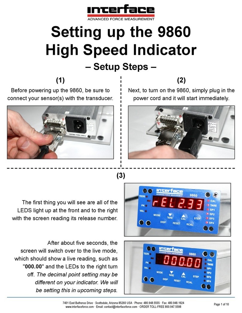
Interface 9860 User instructions
Interface
Interface 9840-400 User manual

Interface
Interface 9860 User manual

Interface
Interface 9325-NU User manual

Interface
Interface INF1 User manual
Interface
Interface DMA2 Manual
